 0
0
OCZ ZX Series 1250 W Review
Voltage Regulation & Efficiency »A Look Inside
Before reading this page we strongly suggest to take a look at this article, which will help you understand the internal components of a PSU much better.
The OEM of the ZX Series 1250 W is Great Wall. Sparkle's Gold Class 1250 W is also built by the same OEM and as you can imagine the two PSUs use the same platform. This platform does not utilize LLC resonant topology in order to achieve Gold efficiency, neither some soft (Zero Voltage Switching - ZVS) switching topology so we don't expect it to exhibit as high efficiency levels as PSUs like the Corsair AX1200 and Antec HCP-1200.
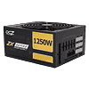
As usual we start with the description of the EMI/transient filtering stage. The latter starts at the AC receptacle with one X and two Y capacitors. It continues on the main PCB with three coils, two X and two Y capacitors. Surprisingly no MOV (Metal Oxide Varistor) is present and this is something unexpected in a hi-end PSU.

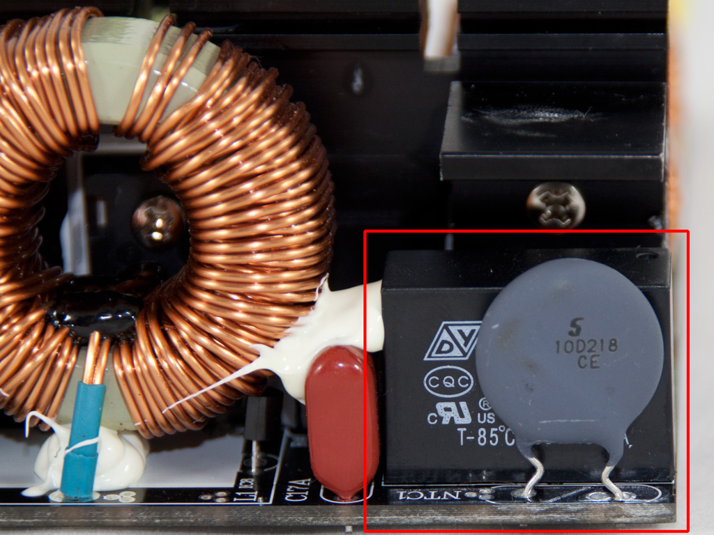
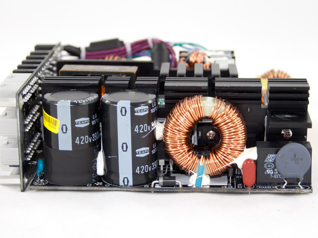


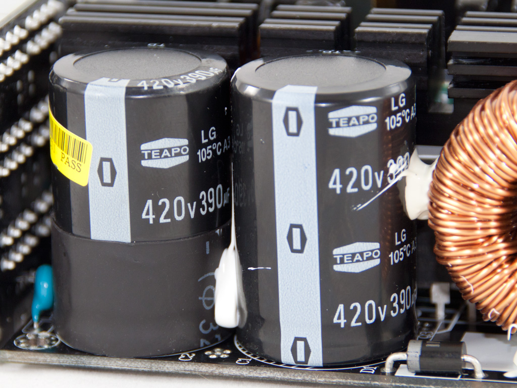

There are two bridge rectifiers cooled passively by three heatsinks. After the bridge rectifiers we find a thermistor and an electromagnetic relay that bypasses it once the PSU is turned on. For APFC three 35N60C3 mosfets are used and the two smoothing capacitors (105°C, 420V, 390µF each) are provided by Teapo. In this stage we expected to find some Japanese capacitors but the used Teapo ones are considered reliable enough. As main switchers we find two 24N60C3. The combo PWM/PFC controller is a Champion CM6802.


The secondary side uses a synchronous design for the generation of +12V. So instead of SBRs (Schottky Barrier Rectifiers) we have seven mosfets (IPP034NE7N3). The minor rails are generated from +12V with the help of two DC-DC converter modules. In each module there are two IPD040N03L and two IPD060N03L mosfets. In front of the DC-DC modules there is a small daughter-board that houses the protections IC, which unfortunately we couldn't identify because the near module was totally blocking the view. All filtering capacitors for the DC outputs are provided by Teapo and are rated at 105°C. Finally, in the secondary side and more specific in the area where +12V is leaving the main PCB we didn't find any shunt resistors, so contrary to the manufacturer's specifications there is no overcurrent protection present.
However OCP in a single +12V rail and with 1250W capacity is almost meaningless anyway. Due to the high output capability of such PSUs (~100 A), they can easily provide 50A+ to a single PCIe connector which will catch fire at that current, yet OCP will not even be close to activating being only at a fraction of the maximum current.


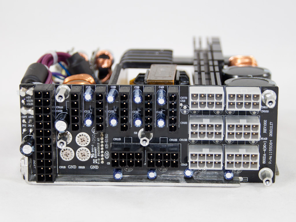
The +12V rail passes to the modular PCB through a big metal bar. The same method is also used for ground where a smaller piece of metal is used. On the front of the modular PCB there are several filtering capacitors (105°C, RGTX series) that further decrease the ripple on the DC outputs. The latter are provided by a Chinese company, Nicon electronics, and it's the first time I encounter them so I have no clue about their reliability.

Soldering quality and workmanship on the main PCB are quite good. In addition we didn't find any long component leads.

The fan is provided by Yate Loon Electronics and its model is D14BH-12 (2800 RPM, 140 CFM, 48.5 dB).
May 13th, 2024 20:31 EDT
change timezone
Latest GPU Drivers
New Forum Posts
- The Filthy, Rotten, Nasty, Helpdesk-Nightmare picture clubhouse (2629)
- Dell Workstation Owners Club (3085)
- Windows 7 Club (1023)
- Lenovo Workstations Owners Club (28)
- Laptop i7 11800H Throttling Immediately (4)
- How can we utilize Artificial Intelligence to help us be more prescient about quality of life and environment? (46)
- 2024 and STILL no dark mode? (45)
- Which Audio System Would you Choose and Why? (24)
- TPU's WCG/BOINC Team (34428)
- Air makes its way from the reservoir into the radiator. (45)
Popular Reviews
- Homeworld 3 Performance Benchmark Review - 35 GPUs Tested
- ZMF Caldera Closed Planar Magnetic Headphones Review
- Corsair MP700 Pro SE 4 TB Review
- ThundeRobot ML903 NearLink Review
- Upcoming Hardware Launches 2023 (Updated Feb 2024)
- AMD Ryzen 7 7800X3D Review - The Best Gaming CPU
- Bykski CPU-XPR-C-I CPU Water Block Review - Amazing Value!
- CHERRY XTRFY M64 Pro Review
- ASUS Radeon RX 7900 GRE TUF OC Review
- ASRock Radeon RX 7900 XT Phantom Gaming White Review
Controversial News Posts
- Intel Statement on Stability Issues: "Motherboard Makers to Blame" (266)
- AMD to Redesign Ray Tracing Hardware on RDNA 4 (227)
- Windows 11 Now Officially Adware as Microsoft Embeds Ads in the Start Menu (172)
- NVIDIA to Only Launch the Flagship GeForce RTX 5090 in 2024, Rest of the Series in 2025 (152)
- Sony PlayStation 5 Pro Specifications Confirmed, Console Arrives Before Holidays (119)
- AMD Hits Highest-Ever x86 CPU Market Share in Q1 2024 Across Desktop and Server (115)
- AMD's RDNA 4 GPUs Could Stick with 18 Gbps GDDR6 Memory (114)
- AMD Ryzen 9 7900X3D Now at a Mouth-watering $329 (104)