 2
2
Super Flower Leadex Gold 750 W Review
Voltage Regulation, Hold-up Time & Inrush Current »A Look Inside & Component Analysis
Before reading this page, we strongly suggest a look at this article, which will help you understand the internal components of a PSU much better. Our main tool for the disassembly of the PSU is a Thermaltronics TMT-9000S soldering and rework station. It is of extreme quality and is equipped with a matching de-soldering gun. With such equipment in hand, breaking apart every PSU is like a walk in the park!


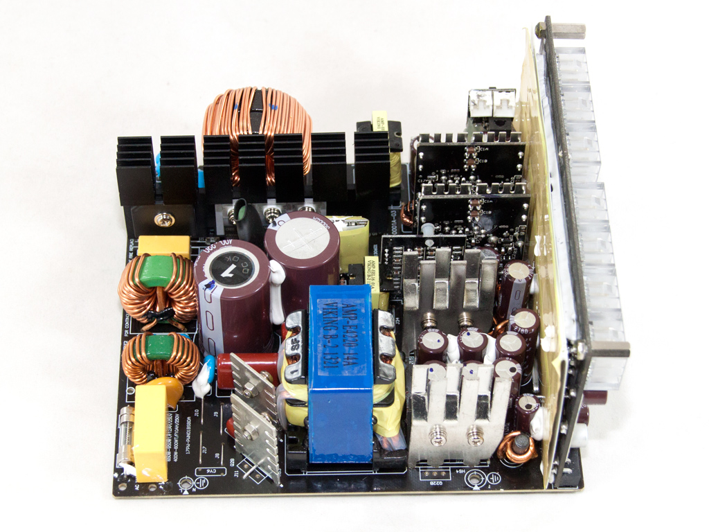
The platform uses a modern design, and while its primary side uses a half-bridge topology, every Leadex unit with a higher capacity uses a full-bridge topology. All Leadex units use an LLC resonant converter with the bridge topology as it offers loss-less switching, which minimizes energy losses. The secondary side uses a synchronous design with mosfets and two DC-DC converters for the generation of the minor rails.
This time the PCB that holds the AC receptacle doesn't host any transient filter components. All of them are on the main PCB: two CM chokes, two X caps, two pairs of Y caps, and an MOV.

A single bridge rectifier is used in the 750 W Leadex.
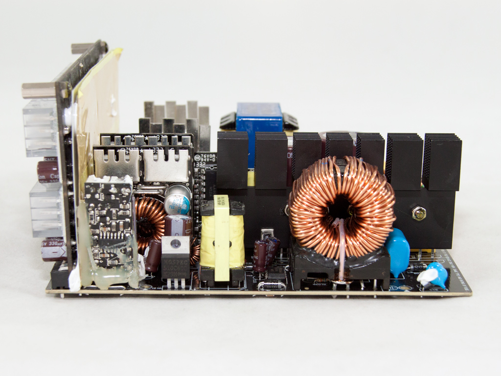


Two Infineon IPP50R199CP fets and a C3D06060A boost diode are used by the APFC converter. The two parallel hold-up caps are located right in front of the transient filter and are by Nippon Chemi-Con (400 V, 330 µF, 105°C, KMR series).

An NTC thermistor protects the unit against large inrush currents and a close-by electromagnetic relay isolates it from the circuit once it finishes its job.

A small, sealed PCB houses the APFC controller, an NCP1653A IC.
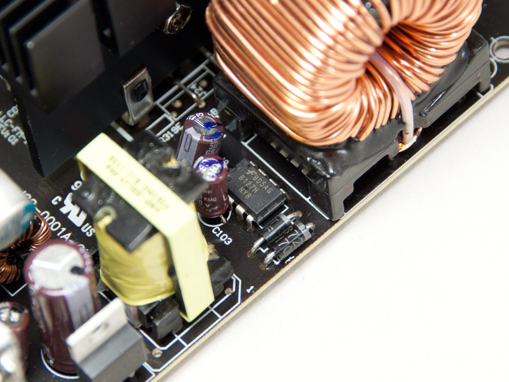
The standby PWM controller is a Fairchild BD5AG IC.
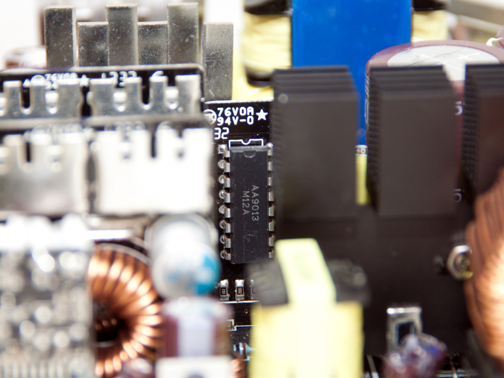
This proprietary IC with markings AA9013 is probably the LLC resonant controller.

Two Infineon IPP50R199CP fets are used as main switches.


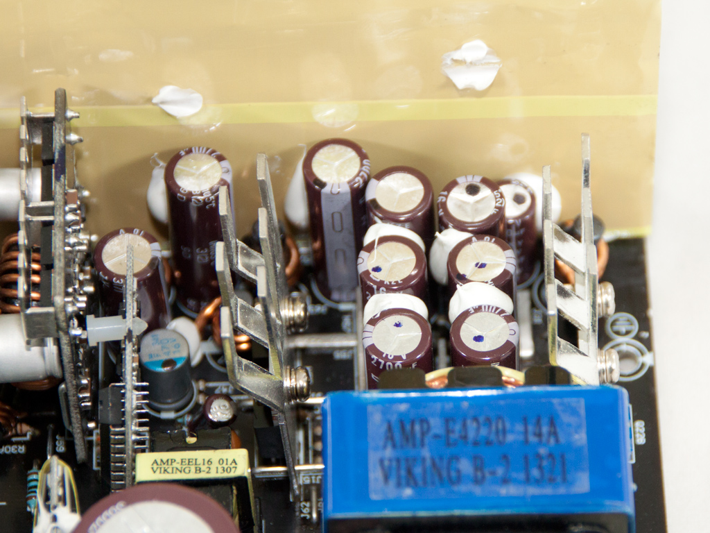
The secondary side has two vertical heatsinks that host four fets in total (4x IPP041N04N). Among the heatsinks are several electrolytic caps by Chemi-Con that are used for ripple-filtering purposes.

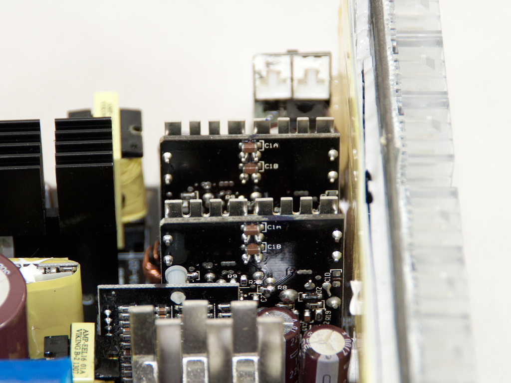
Two DC-DC converters generate the minor rails. The polymer caps on these are provided by Chemi-Con.

The 5VSB rail is rectified by a Mospec S10C60C SBR (Schottky Barrier Rectifier), and the fan control board with an LM324ADC is installed right next to it. We had to apply lots of glue to the aforementioned control board to properly secure it since accidently snapping it off its soldered base would have been very easy.

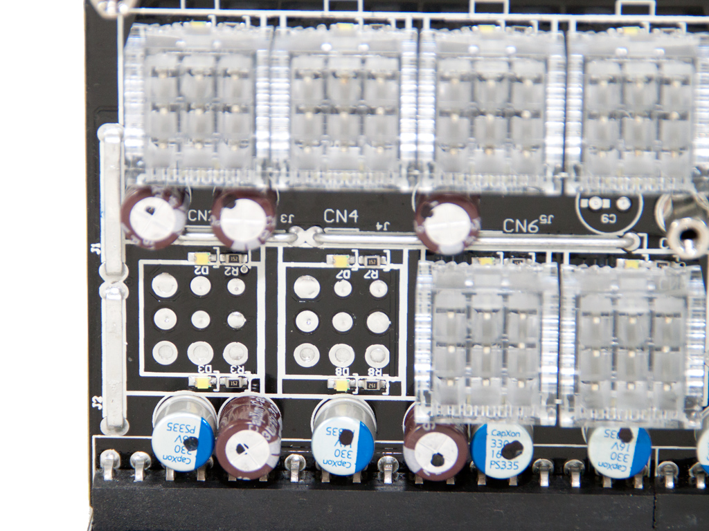


The front of the modular PCB is covered in many polymer caps and several small electrolytic caps by CapXon. It doesn't matter whether these are made in Japan or China since caps in this area are not stressed significantly. Polymer caps also last for a very long regardless of their origin.


Soldering quality is good but definitely not topnotch. However, SF is on the right track.

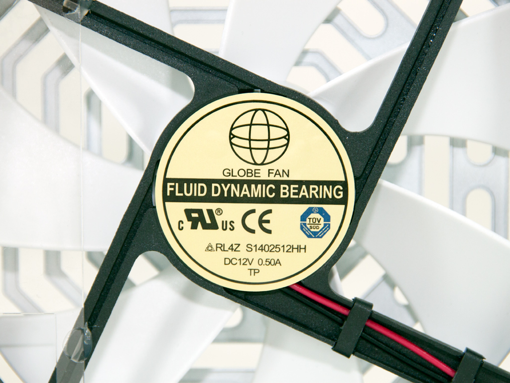
The fan is provided by Globe Fan, and its model number is RL4Z S1402512HH (12 V, 0.5 A, 1800 RPM, 135.74 CFM, 36.7 dBA). The same fan is used by the Rosewill Tachyon 1000 W unit, a re-badged SF PSU. The "S" nomenclature in the model number usually stands for a sleeve bearing, but the label on its centerpiece is indicative of a Fluid Dynamic bearing. Globe Fan probably used an upgraded sleeve bearing they call FDB. Finally, a small plastic baffle is attached to the fan. It funnels air toward the rear of the unit.
Apr 26th, 2024 06:17 EDT
change timezone
Latest GPU Drivers
New Forum Posts
- What's your latest tech purchase? (20347)
- Share your AIDA 64 cache and memory benchmark here (2918)
- Secure boot already open help (1)
- What are you playing? (20535)
- Best SSD for system drive (83)
- TPU's Nostalgic Hardware Club (18472)
- Last game you purchased? (258)
- Alphacool CORE 1 CPU block - bulging with danger of splitting? (22)
- Nvidia CMP 100-210 or 100HX (GV100 GPU) (9)
- Horizontal black lines popping up on my screen? (7)
Popular Reviews
- HYTE THICC Q60 240 mm AIO Review
- Alienware Pro Wireless Gaming Keyboard Review
- MOONDROP x Crinacle DUSK In-Ear Monitors Review - The Last 5%
- Upcoming Hardware Launches 2023 (Updated Feb 2024)
- Thermalright Phantom Spirit 120 EVO Review
- RTX 4090 & 53 Games: Ryzen 7 5800X vs Ryzen 7 5800X3D Review
- ASUS Radeon RX 7900 GRE TUF OC Review
- NVIDIA RTX 4090: 450 W vs 600 W 12VHPWR - Is there any notable performance difference?
- RTX 4090 & 53 Games: Core i9-13900K vs Ryzen 7 5800X3D Review
- FiiO K19 Desktop DAC/Headphone Amplifier Review
Controversial News Posts
- Windows 11 Now Officially Adware as Microsoft Embeds Ads in the Start Menu (122)
- Sony PlayStation 5 Pro Specifications Confirmed, Console Arrives Before Holidays (117)
- NVIDIA Points Intel Raptor Lake CPU Users to Get Help from Intel Amid System Instability Issues (106)
- AMD "Strix Halo" Zen 5 Mobile Processor Pictured: Chiplet-based, Uses 256-bit LPDDR5X (101)
- US Government Wants Nuclear Plants to Offload AI Data Center Expansion (98)
- AMD's RDNA 4 GPUs Could Stick with 18 Gbps GDDR6 Memory (89)
- Developers of Outpost Infinity Siege Recommend Underclocking i9-13900K and i9-14900K for Stability on Machines with RTX 4090 (85)
- Windows 10 Security Updates to Cost $61 After 2025, $427 by 2028 (84)