 31
31
Zaward Twin Towers Chipset Cooler Review
Performance »Installation


Due to its size the Twin Towers is not a universal cooling solution. Here the cooler was placed over the chipset fan on a DFI NF4 Ultra-D. A video card of almost any length will surely come in contact with the cooler when in the top PCI-express slot. Instead, the Twin Towers would have to be installed on an Intel testbed, consisting of an Intel 975X northbridge. There are two long, slotted strips of metal that are used to make the mounting adjustable. These are attached with the two smaller screws in the package to the bracket already mounted to the heatsink. The hooks are made by putting together the longer screws with the hooks and two nuts. These must be tightened completely to avoid installation trouble later.


The hook assembly then gets passed through each slot on the metal brackets and is held in place with the second nut. These should not be fully tightened yet, but approximately half way.


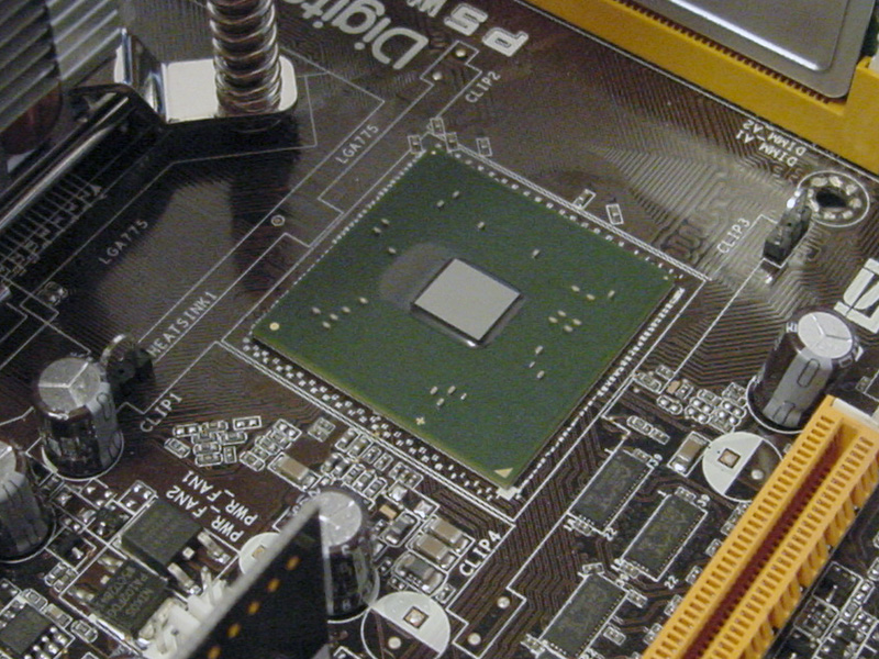
The next step was to remove the stock chipset cooler and clean the chipset to remove any residual thermal compound.


Next, the foam pad needs to be removed from the protective paper and applied to the base of the heatsink. This step can be a little tricky, and can be completed easiest by following the edge of the base without leaving any copper showing. Making the loop too small will leave a lump at the last spot the pad is attached to, and removing the pad will cause it to be stretched out. Also, some thermal compound needs to be applied to the chipset die: in this case, Arctic Silver Ceramique.

While holding the heatsink above the chipset to avoid contact with the thermal compound, place each hook under the mounting loops on the motherboard. Tighten the nut on each side until they are snug, making sure to center the base over the chipset. If the nuts on the hook assembly are not tight, the screw will spin while trying to tighten these nuts.


The Twin Towers was removed immediately to check the contact with the chipset. All of the extra compound was squeezed out to the sides and contact was excellent.
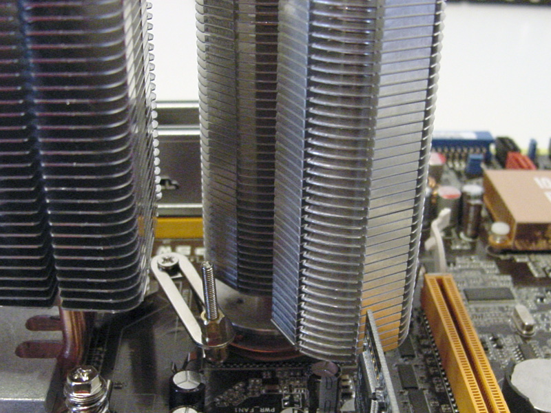

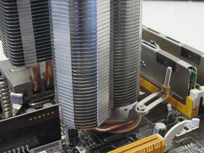
The base was cleaned and new thermal compound was applied, and the heatsink was reinstalled. The secondary heatpipe can be turned to avoid any other components on the board, and should be done before the nuts are tightened. The best place on this motherboard was between the first PCI-express 16x slot and the built-in wireless NIC. The other sides would have interfered with the memory or the CPU heatsink. Although it looks close, nothing is touching the Twin Towers. Before installation, the second heatpipe rotated freely, causing concern that it might shift and come in contact with the video card when installed in a tower case. However, this was not the case; when the mounting hardware is tightened the secondary heatpipe no longer moves freely, and is completely snug.


The Twin Towers would be tested on the system with the Zaward Vivo, which is a 92mm based heatsink. When the cover was placed on the Vivo, there is little room between it and the twin Towers, but again, they do not touch. If a larger 120mm heatsink was used there may not have been enough room for the chipset heatsink to be installed. Since the original northbridge heatsink had a heatpipe that led to the MOSFETs, removing the stock cooler also removed the MOSFET cooling. To solve this, the heatpipe was removed from the stock cooler and the original heatsink was replaced.
Apr 26th, 2024 06:19 EDT
change timezone
Latest GPU Drivers
New Forum Posts
- What's your latest tech purchase? (20347)
- Share your AIDA 64 cache and memory benchmark here (2918)
- Secure boot already open help (1)
- What are you playing? (20535)
- Best SSD for system drive (83)
- TPU's Nostalgic Hardware Club (18472)
- Last game you purchased? (258)
- Alphacool CORE 1 CPU block - bulging with danger of splitting? (22)
- Nvidia CMP 100-210 or 100HX (GV100 GPU) (9)
- Horizontal black lines popping up on my screen? (7)
Popular Reviews
- HYTE THICC Q60 240 mm AIO Review
- Alienware Pro Wireless Gaming Keyboard Review
- MOONDROP x Crinacle DUSK In-Ear Monitors Review - The Last 5%
- Upcoming Hardware Launches 2023 (Updated Feb 2024)
- Thermalright Phantom Spirit 120 EVO Review
- RTX 4090 & 53 Games: Ryzen 7 5800X vs Ryzen 7 5800X3D Review
- ASUS Radeon RX 7900 GRE TUF OC Review
- NVIDIA RTX 4090: 450 W vs 600 W 12VHPWR - Is there any notable performance difference?
- RTX 4090 & 53 Games: Core i9-13900K vs Ryzen 7 5800X3D Review
- FiiO K19 Desktop DAC/Headphone Amplifier Review
Controversial News Posts
- Windows 11 Now Officially Adware as Microsoft Embeds Ads in the Start Menu (123)
- Sony PlayStation 5 Pro Specifications Confirmed, Console Arrives Before Holidays (117)
- NVIDIA Points Intel Raptor Lake CPU Users to Get Help from Intel Amid System Instability Issues (106)
- AMD "Strix Halo" Zen 5 Mobile Processor Pictured: Chiplet-based, Uses 256-bit LPDDR5X (101)
- US Government Wants Nuclear Plants to Offload AI Data Center Expansion (98)
- AMD's RDNA 4 GPUs Could Stick with 18 Gbps GDDR6 Memory (89)
- Developers of Outpost Infinity Siege Recommend Underclocking i9-13900K and i9-14900K for Stability on Machines with RTX 4090 (85)
- Windows 10 Security Updates to Cost $61 After 2025, $427 by 2028 (84)