ASUS P5P800 Vdroop Mod |
|
|
Author: CaTalyst.X
Date: 2005-07-29 16:28:48
|
|
Introduction
The ASUS P5P800 uses an Analog Devices ADP3180 4 Phase 12V 28-Lead TSSOP PWM Voltage Regulator (Datasheet) to control CPU VCore.This is the same chip ASUS has used on their other popular Pentium 4 motherboards. When using all four phases, the CPU VCore is very stable, however the P5P800 only utilizes a three phase power circuit. This results in a drop in VCore under load which can cause crashing and instability.
The solution to this is to shunt pins 17 (CSSUM) and 18 (CSCOMP) of ADP3180 with a 50K variable resistor set at 28k Ohms.
Pin 18 is a Current Sense Compensation point, a resistor and capacitor from CSCOMP to CSSUM determines the slope of the load line, by changing the resistance between these two pins, we are able to even out the load line and stabilize CPU VCore.
Materials List
You will need the following tools and supplies to perform this modification:- Soldering Iron(15W-45W)
- .032 (or smaller) Rosin Core Solder
- Hot Glue or Liquid Electrical Tape (To attach the trimmer and protect solder joints)
- 50k Ohm trimmer (15 turns or more)
- Digital Multimeter (To measure trimmer resistance)
- 26-30AWG Insulated Wire
The Mod
We start by setting the 50k multiturn trimmer at 28k Ohms. It doesnt have to be exact, but as close as you can get it, the closer the better. 28k has shown to be the optimal resistance to keep droop as small as possible.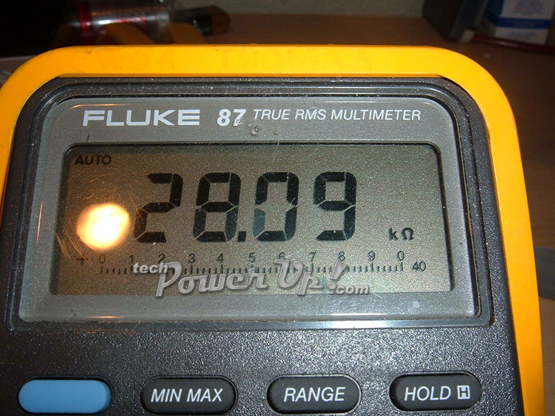
It is very hard to solder directly to the legs of ADP3180, so instead we solder to these alternate points that are directly connected to pins 17 and 18.
Double check to make sure your trimmer is set at 28k Ohms and begin!
Use only the top two or the bottom two legs for this mod. There is no polarity to worry about here, but I suggest you snip off the leg you aren't using, so you dont get confused.
Solder wires from the trimmer to our alternate points as shown. Try to use the shortest wires possible to keep EMI at a minimum.
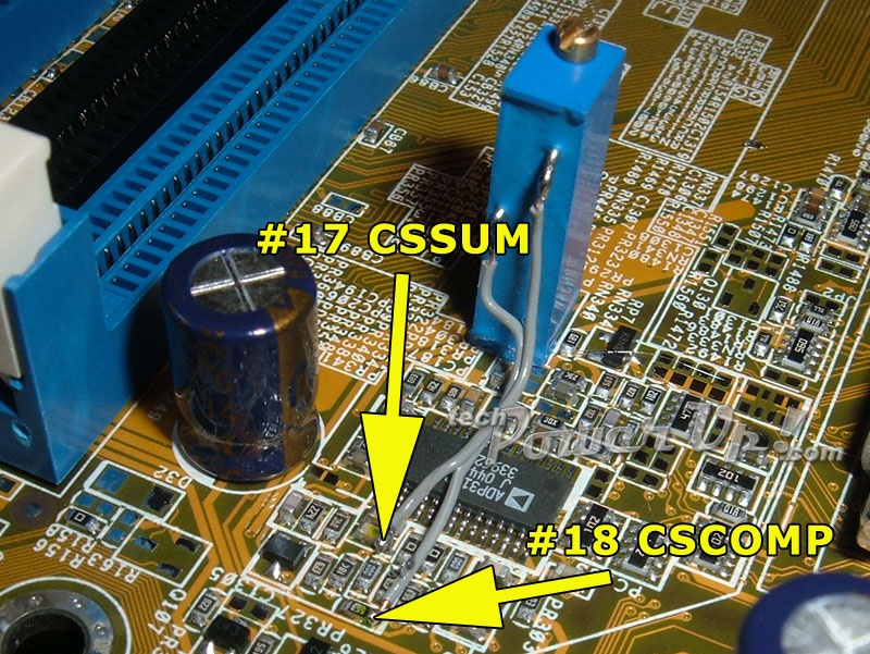
Your mod should look something like the one above.
Next step is to clean all the solder joints thoroughly with Rubbing Alcohol.
Now, use some hot glue or super glue to attach the trimmer to the motherboard, and some hot glue or liquid electrical tape to protect your newly soldered joints.
Apr 26th, 2024 13:30 EDT
change timezone
Latest GPU Drivers
New Forum Posts
- The Official Linux/Unix Desktop Screenshots Megathread (702)
- What's your latest tech purchase? (20352)
- hacked (73)
- im new to throttelstop and i think i messed it up by copying others any hints would be very much aprreciated (5)
- 2022-X58/1366 PIN Motherboards NVME M.2 SSD BIOS MOD Collection (657)
- DTS DCH Driver for Realtek HDA [DTS:X APO4 + DTS Interactive] (1909)
- checkup (1)
- Help me to OC my 5700X (10)
- XFX RX470 8GB no video and error 43 (28)
- The TPU UK Clubhouse (24788)
Popular Reviews
- HYTE THICC Q60 240 mm AIO Review
- MOONDROP x Crinacle DUSK In-Ear Monitors Review - The Last 5%
- Alienware Pro Wireless Gaming Keyboard Review
- Upcoming Hardware Launches 2023 (Updated Feb 2024)
- Thermalright Phantom Spirit 120 EVO Review
- FiiO K19 Desktop DAC/Headphone Amplifier Review
- ASUS Radeon RX 7900 GRE TUF OC Review
- RTX 4090 & 53 Games: Ryzen 7 5800X vs Ryzen 7 5800X3D Review
- NVIDIA RTX 4090: 450 W vs 600 W 12VHPWR - Is there any notable performance difference?
- AMD Ryzen 7 7800X3D Review - The Best Gaming CPU
Controversial News Posts
- Windows 11 Now Officially Adware as Microsoft Embeds Ads in the Start Menu (128)
- Sony PlayStation 5 Pro Specifications Confirmed, Console Arrives Before Holidays (117)
- NVIDIA Points Intel Raptor Lake CPU Users to Get Help from Intel Amid System Instability Issues (106)
- AMD "Strix Halo" Zen 5 Mobile Processor Pictured: Chiplet-based, Uses 256-bit LPDDR5X (102)
- US Government Wants Nuclear Plants to Offload AI Data Center Expansion (98)
- AMD's RDNA 4 GPUs Could Stick with 18 Gbps GDDR6 Memory (92)
- Developers of Outpost Infinity Siege Recommend Underclocking i9-13900K and i9-14900K for Stability on Machines with RTX 4090 (85)
- Windows 10 Security Updates to Cost $61 After 2025, $427 by 2028 (84)