A Detailed Look Into PSUs |
|
PWM Controller - Isolator
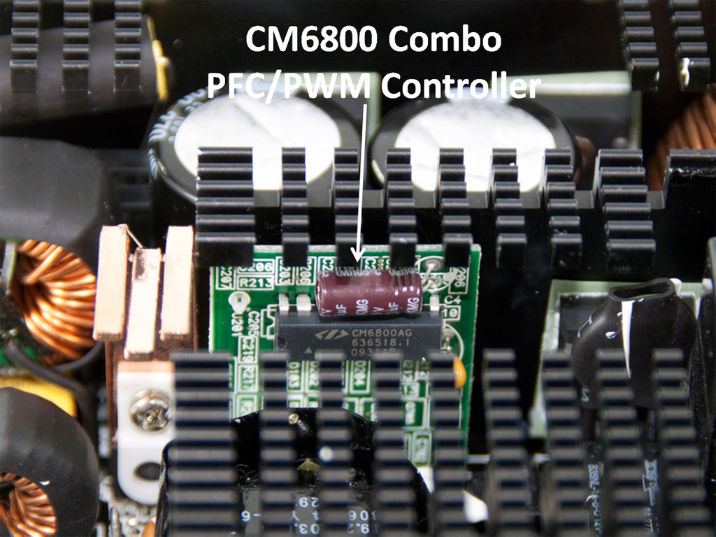

The main purpose of the PWM controller is to maintain a regulated output voltage and control the amount of energy being delivered to the load (system). The aforementioned are accomplished by adjusting the duty cycle of the main switches. The duty cycle can be adjusted from 0 to 100 percent but usually its range is smaller. With great approximation we could say that output voltage is the product of input voltage and duty cycle (Vout = Vin × duty cycle).
The PWM controller uses a voltage reference as the PSUs “ideal” reference to which the output voltage is constantly compared. In the PWM IC there is a voltage error amplifier that performs a high gain voltage comparison between the output voltage and the above-mentioned reference. According to this comparison an error voltage-to-pulse width converter sets the duty cycle in response to the level of the error voltage from the voltage error amplifier. Besides determining the duty cycle of the main switches the PWM controllers usually incorporate and other functionalities, as soft-start circuit which starts the PSU smoothly reducing large inrush currents, over-current amplifier that protects the PSU from overloading, undervoltage lockout that prevents the PSU starting when the voltage within the control IC is too small to drive the main switches etc.

In order for the voltage feedback, from the DC outputs, to reach the voltage error amplifier of the PWM IC an isolated feedback is needed. There are two methods of electrical isolation, optical (optoisolator) and magnetic (transformer). In modern PSUs optoisolators are commonly used. The voltage error amplifier is placed on the secondary side of the optoisolator.
Apr 23rd, 2024 02:39 EDT
change timezone
Latest GPU Drivers
New Forum Posts
- Red Dead Redemption using emu (0)
- Sexy Mechanical Keyboard Thread (479)
- Cinebench crashed my PC. My Wi-Fi stopped working, and I keep getting a "Please wait" screen when I boot up my PC. (23)
- Which new games will you be buying? (294)
- What are you playing? (20517)
- EK seems to be having major issues (23)
- The TPU UK Clubhouse (24764)
- Why MS buying all of these Studios is bad for Gaming (12)
- Linus watercools (56)
- ASRock Deskmini Owner's Club (27)
Popular Reviews
- Horizon Forbidden West Performance Benchmark Review - 30 GPUs Tested
- Fractal Design Terra Review
- Corsair 2000D Airflow Review
- Thermalright Phantom Spirit 120 EVO Review
- Minisforum EliteMini UM780 XTX (AMD Ryzen 7 7840HS) Review
- ASUS GeForce RTX 4090 STRIX OC Review
- NVIDIA GeForce RTX 4090 Founders Edition Review - Impressive Performance
- ASUS GeForce RTX 4090 Matrix Platinum Review - The RTX 4090 Ti
- Creative Pebble X Plus Review
- MSI GeForce RTX 4090 Gaming X Trio Review
Controversial News Posts
- Sony PlayStation 5 Pro Specifications Confirmed, Console Arrives Before Holidays (115)
- NVIDIA Points Intel Raptor Lake CPU Users to Get Help from Intel Amid System Instability Issues (105)
- AMD "Strix Halo" Zen 5 Mobile Processor Pictured: Chiplet-based, Uses 256-bit LPDDR5X (101)
- US Government Wants Nuclear Plants to Offload AI Data Center Expansion (98)
- Windows 10 Security Updates to Cost $61 After 2025, $427 by 2028 (84)
- Developers of Outpost Infinity Siege Recommend Underclocking i9-13900K and i9-14900K for Stability on Machines with RTX 4090 (82)
- TechPowerUp Hiring: Reviewers Wanted for Motherboards, Laptops, Gaming Handhelds and Prebuilt Desktops (74)
- Intel Realizes the Only Way to Save x86 is to Democratize it, Reopens x86 IP Licensing (70)