The problem is that I am Argentine, here we do not have Asus service, much less could I contact Der8auer
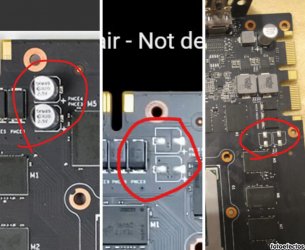
Hey guys, I found this but I'm not sure if it's the problem. In the first photo we see a photo taken from the link provided by
@Anoniem , in the second we see a capture of the gpu of the video that I passed previously, and in the third my gpu.
In the video the problem is not that and in the end the gpu works, I think it comes from the factory like that, maybe in the link that Anoniem provided is not the exactly model.
What do yo think?


") Might want to check if there is any reputable shop that does SMD repair and all. Ask them what their hourly rate is and try to make a deal about how much time they're allowed to spend on it. It's a really tricky situation since getting a new card might be a bit of a challenge and these repairs can be quite expensive.
Might want to check if there is any reputable shop that does SMD repair and all. Ask them what their hourly rate is and try to make a deal about how much time they're allowed to spend on it. It's a really tricky situation since getting a new card might be a bit of a challenge and these repairs can be quite expensive.