
- Joined
- Jan 6, 2007
- Messages
- 2,555 (0.38/day)
- Location
- Illinois
| Processor | i7 2600k@4.6ghz |
|---|---|
| Motherboard | MSI z68ma-ed55 |
| Cooling | Silentx Extreem 120mm |
| Memory | 2x4gb XMS 7-8-7-20 1600 |
| Video Card(s) | HD6870 |
| Storage | 2x128gb Kingston Hyper-X (Raid0), 2x750gb RE3 (RAID1), 2x750gb RE3 (RAID1) |
| Display(s) | Soyo 24", Gateway 22" |
| Case | Fractal Design Arc Mini 6x120mm fans. |
| Audio Device(s) | Onboard |
| Power Supply | Zalman 750w |
| Software | Windows 7 |
So you want 4pin PWM control of your new 3pin CPU fan?
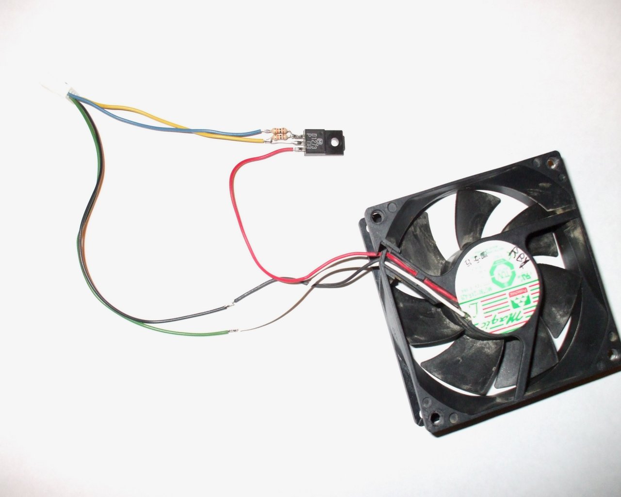
I don't know if anyone can use this but I drew it up because I might need it in my ITX build. Feel free to try it.
What it is:
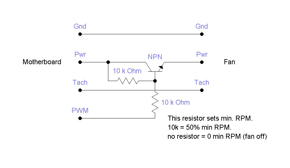
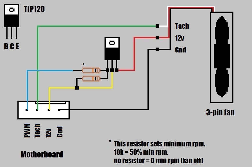
So you went out and bought a high quality aftermarket heatsink/fan but most of them only come with a 3-pin fan. Or maybe you want to use the cpu's fan controller to power additional fans. Or perhapse you want to take advantage of a high speed fan but you don't want to hear it or fork out the cash or deal with adjusting a manual fan controller. Most motherboards have cpu fan throttling adjustments in the bios but you can't take advantage of them with your new 3pin fan! This schematic shows you how to use only 3 components to allow the motherboard's 4-pin CPU fan connector to control 2 or 3-pin fans.
The motherboard's 4-pin fan header:
The 4-pin fan connector has power, ground, tach, and PWM connections. The PWM signal from the motherboard is open or grounded. When the signal is open the fan opperates at full speed. When the signal is grounded the fan is at it's lowest speed. The motherboard controls the fan by switching between these states.
How it works:
The transistor is held in the 'on' state by applying a current to it's base via. the 10k resistor from +12v to the base. The PWM signal from the motherboard sinks (grounds) the base to turn off the transistor. This resistor is needed to both turn the device on and limit the amount of current the motherboard has to sink to 1.2ma. The second resistor, also 10k, limits how low the pwm signal can sink it (and subsequently reduces the current current the motherboard's pwm circuit to .6ma). This keeps the fan opperating at a minimum RPM.
The NPN transistor was chosen because they are generally easier to find.
The 10k resistor in series with the PWM signal can be substituted with a 10k pot to give you 0-50% adjustability of the MINIMUM fan RPM.
I don't know if anyone can use this but I drew it up because I might need it in my ITX build. Feel free to try it.
What it is:
So you went out and bought a high quality aftermarket heatsink/fan but most of them only come with a 3-pin fan. Or maybe you want to use the cpu's fan controller to power additional fans. Or perhapse you want to take advantage of a high speed fan but you don't want to hear it or fork out the cash or deal with adjusting a manual fan controller. Most motherboards have cpu fan throttling adjustments in the bios but you can't take advantage of them with your new 3pin fan! This schematic shows you how to use only 3 components to allow the motherboard's 4-pin CPU fan connector to control 2 or 3-pin fans.
The motherboard's 4-pin fan header:
The 4-pin fan connector has power, ground, tach, and PWM connections. The PWM signal from the motherboard is open or grounded. When the signal is open the fan opperates at full speed. When the signal is grounded the fan is at it's lowest speed. The motherboard controls the fan by switching between these states.
How it works:
The transistor is held in the 'on' state by applying a current to it's base via. the 10k resistor from +12v to the base. The PWM signal from the motherboard sinks (grounds) the base to turn off the transistor. This resistor is needed to both turn the device on and limit the amount of current the motherboard has to sink to 1.2ma. The second resistor, also 10k, limits how low the pwm signal can sink it (and subsequently reduces the current current the motherboard's pwm circuit to .6ma). This keeps the fan opperating at a minimum RPM.
The NPN transistor was chosen because they are generally easier to find.
The 10k resistor in series with the PWM signal can be substituted with a 10k pot to give you 0-50% adjustability of the MINIMUM fan RPM.
Attachments


Last edited:


")
