 7
7
be quiet! Pure Power 11 FM 750 W Review
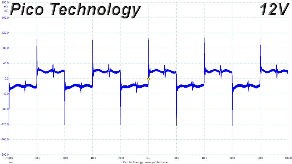
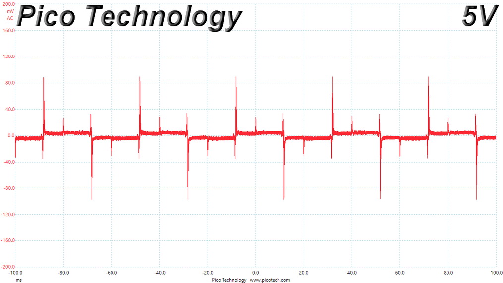
Protection Features, Power Sequencing & EMC »Advanced Transient Response Tests
In these tests, we monitor the response of the PSU in two different scenarios. First, a transient load (15 A at +12V, 6 A at +5V, 6 A at +3.3V, and 0.5 A at 5VSB) is applied to the PSU for 20 ms while it is working at 20% load. In the second scenario, the PSU, while working at 50% load, is hit by the same transient load. In both tests, our oscilloscope measures the voltage drops caused by the transient load. All voltages should remain within the regulation limits defined by the ATX specification.During real-world usage, a PSU always operates under changing loads, depending on whether the CPU or graphics card is busy. It is of immense importance that the PSU is able to keep its rails within the limits defined by the ATX specification. Smaller deviations reduce the stress being applied to system components.
We should note that the ATX specification requires for capacitive loading during the transient tests, but in our methodology, we chose to apply the worst-case scenario with no extra capacitance on the rails. Although the ATX specification asks for this capacitance, your system—the mainboard and its other parts—may not provide it, which we have to keep in mind as well.
| Advanced Transient Response 20% - 50 Hz | ||||
|---|---|---|---|---|
| Voltage | Before | After | Change | Pass/Fail |
| 12 V | 12.163V | 11.994V | 1.39% | Pass |
| 5 V | 5.058V | 4.973V | 1.68% | Pass |
| 3.3 V | 3.291V | 3.160V | 3.98% | Pass |
| 5VSB | 5.038V | 4.980V | 1.15% | Pass |
| Advanced Transient Response 20% - 50 Hz | ||||
|---|---|---|---|---|
| Voltage | Before | After | Change | Pass/Fail |
| 12 V | 12.163V | 11.994V | 1.39% | Pass |
| 5 V | 5.058V | 4.973V | 1.68% | Pass |
| 3.3 V | 3.291V | 3.160V | 3.98% | Pass |
| 5VSB | 5.038V | 4.980V | 1.15% | Pass |
Transient response is good on all rails but 3.3 V, where there is room for improvement.
Below are the oscilloscope screenshots we took during Advanced Transient Response testing.
Transient Response at 20% Load


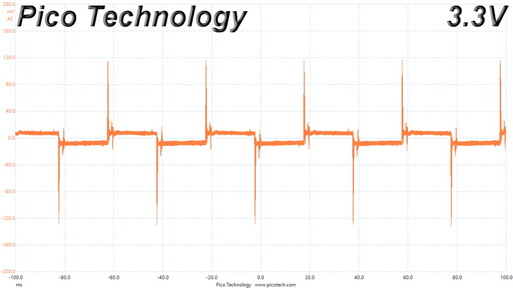
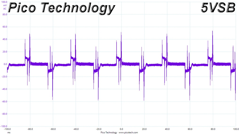
Transient Response at 50% Load


Turn-on Transient Tests
We measure the response of the PSU in more straightforward scenarios of transient load—during the power-on phase of the PSU—in the next set of tests. In the first test, we turn the PSU off, dial the maximum current the 5VSB can output, and then switch on the PSU. In the second test, we dial the maximum load +12V can handle and start the PSU while the PSU is in standby mode. In the last test, while the PSU is completely switched off (we cut off power or switch the PSU off by flipping its on/off switch), we dial the maximum load the +12V rail can handle before switching the PSU on from the loader and restoring power. The ATX specification states that recorded spikes on all rails should not exceed 10% of their nominal values (e.g., +10% for +12V is 13.2 V and 5.5 V for +5V).

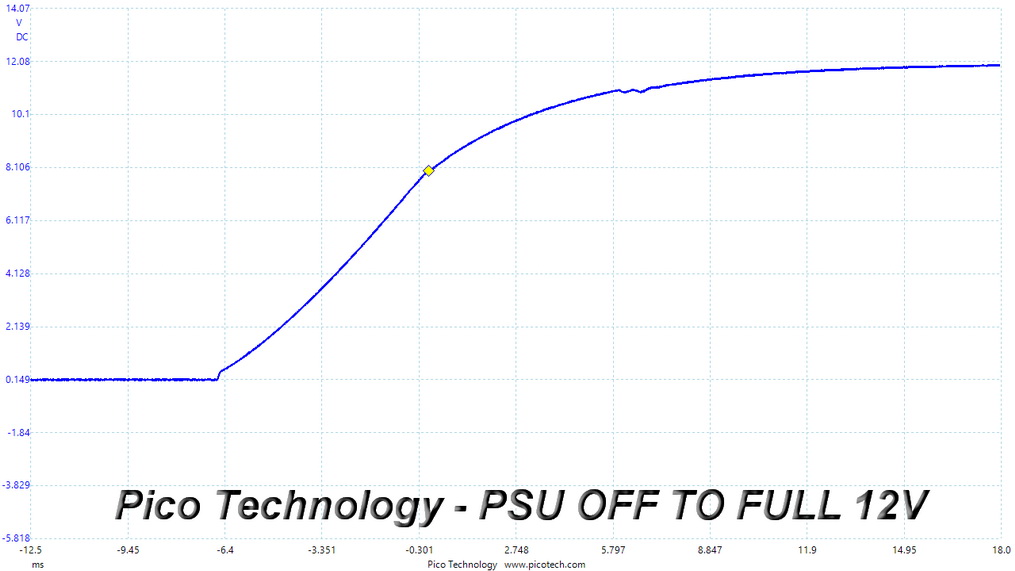
Inrush Current
Inrush current, or switch-on surge, refers to the maximum, instantaneous input current drawn by an electrical device when it is first turned on. Large enough inrush current can cause the tripping of circuit breakers and fuses and may also damage switches, relays, and bridge rectifiers. As a result, the lower the inrush current of a PSU right as it is turned on, the better.
Inrush current is high with 230 V input.
Leakage Current
We use a GW Instek GPT-9904 electrical safety tester to measure the leakage current. According to the IEC-60950-1 regulation, no power supply should exceed 3.5 mA of leakage current, which is low enough not to harm anyone touching the chassis. This test is performed at 110% of the rated input voltage.
Leakage current is low.
Apr 26th, 2024 11:14 EDT
change timezone
Latest GPU Drivers
New Forum Posts
- The TPU UK Clubhouse (24787)
- Cs2 Freezing in Rx 580 (5)
- im new to throttelstop and i think i messed it up by copying others any hints would be very much aprreciated (4)
- Ghost of Tsushima PC Port !!!! (15)
- The Official Linux/Unix Desktop Screenshots Megathread (699)
- Red Dead Redemption using emu (4)
- Meta Horizon OS (21)
- Old high quality PSU, or semi-old mid-quality PSU? (3)
- Secure boot already open help (8)
- What are you playing? (20540)
Popular Reviews
- HYTE THICC Q60 240 mm AIO Review
- MOONDROP x Crinacle DUSK In-Ear Monitors Review - The Last 5%
- Alienware Pro Wireless Gaming Keyboard Review
- Upcoming Hardware Launches 2023 (Updated Feb 2024)
- Thermalright Phantom Spirit 120 EVO Review
- ASUS Radeon RX 7900 GRE TUF OC Review
- FiiO K19 Desktop DAC/Headphone Amplifier Review
- RTX 4090 & 53 Games: Ryzen 7 5800X vs Ryzen 7 5800X3D Review
- NVIDIA RTX 4090: 450 W vs 600 W 12VHPWR - Is there any notable performance difference?
- RTX 4090 & 53 Games: Core i9-13900K vs Ryzen 7 5800X3D Review
Controversial News Posts
- Windows 11 Now Officially Adware as Microsoft Embeds Ads in the Start Menu (125)
- Sony PlayStation 5 Pro Specifications Confirmed, Console Arrives Before Holidays (117)
- NVIDIA Points Intel Raptor Lake CPU Users to Get Help from Intel Amid System Instability Issues (106)
- AMD "Strix Halo" Zen 5 Mobile Processor Pictured: Chiplet-based, Uses 256-bit LPDDR5X (101)
- US Government Wants Nuclear Plants to Offload AI Data Center Expansion (98)
- AMD's RDNA 4 GPUs Could Stick with 18 Gbps GDDR6 Memory (92)
- Developers of Outpost Infinity Siege Recommend Underclocking i9-13900K and i9-14900K for Stability on Machines with RTX 4090 (85)
- Windows 10 Security Updates to Cost $61 After 2025, $427 by 2028 (84)