 13
13
Cooler Master V Series 550 W Review
Load Regulation, Hold-up Time & Inrush Current »A Look Inside & Component Analysis
Before reading this page, we strongly suggest a look at this article, which will help you understand the internal components of a PSU better. Our main tool for the disassembly is a Thermaltronics TMT-9000S soldering and rework station. It is of extreme quality and is equipped with a matching de-soldering gun. With such equipment in hand, breaking apart every PSU is like a walk in the park!| Corsair V550 Parts Description | |
|---|---|
| Primary Side | |
| Transient Filter | 4x Y caps, 3x X caps, 2x CM chokes, 1x MOV |
| Bridge Rectifier(s) | 1x |
| Inrush Current Protection | NTC Thermistor |
| APFC Mosfets | 2x Infineon IPP50R280CE (650V, 12.8A @ 100°C, 0.19 mΩ) |
| APFC Boost Diode | 1x STTH8R06D (600V, 12A @ 175°C) |
| Hold-up Cap(s) | 1x Nippon Chemi-Con (450V, 390 uF, 105°C, KMR series, 2000h @ 105°C). |
| Main Switchers | 2x MagnaChip MDP18N50 (500V, 11A @ 100°C, 0.27 Ohm) |
| APFC Controller | Champion CM6500TNX - CM03X |
| Switching Controller | Champion CM6901 |
| Topology | Primary side: Half Bridge Secondary side: Synchronous Rectification & DC-DC converters |
| Secondary Side | |
| +12V | 4x Infineon IPP041N04N G (40V, 80A @ 100°C, 4.1 mΩ) |
| 5V & 3.3V | DC-DC Converters: 2x Infineon BSC050NE2LS FETs (30V, 48A @ 100°C, 6.9mΩ @ 125°C) PWM Controllers: 2x APW7073 |
| Filtering Capacitors | Electrolytics: Nippon Chemi-Con (105°C, KY, KZE), United Chemi-Con (105°C, LXZ), Suncon (105°C), Rubycon (105°C) Polymers: Unicon (TW) |
| Supervisor IC | SITI PS223 (OVP, UVP, OCP, SCP, OTP) |
| Fan Model | Silencio A12025-25RB-2IN-F1 (120mm, 12 V, 0.16 A, 2250 RPM, Loop Dynamic Bearing) |
| 5VSB Circuit | |
| Rectifying Diode | PFR10V45CT |
| Standby PWM Controller | Sanken STR-A6069H |


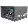
As has already been mentioned, this PSU is made by Enhance Electronics. The platform is up-to-date, and in the primary side, we find a half-bridge topology and an LLC resonant converter for a significant efficiency boost, especially at higher loads. A synchronous design and two VRMs (Voltage Regulation Modules), which generate the minor rails, are used in the secondary side.
For an Enhance platform, the heatsinks are quite small. Enhance usually uses large heatsinks with long fins, but there apparently wasn't enough space on the small mainboard for such large heatsinks. The small heatsinks were a big relief since it made identifying the parts easier as we only had to desolder the APFC cap. Cooler Master's so-called 3D circuit in the secondary side is actually a vertical daughter-board that takes on the role power-transfer cables have in other PSUs. Cooler Master used a very fancy name for this particular board, but marketing usually uses fancy words that will help a product stand out from the crowd. Personally, we believe a product's performance, reliability, and support to make the real difference in sales.
At the AC receptacle, an X and two Y caps form the first part of the EMI filter. We find the rest of the filter on the mainboard, made up of two Y caps, an X cap, two CM chokes, and an MOV. As you can see, the EMI filter is thus complete.

The single bridge rectifier is bolted to the APFC heatsink, and since its markings are hidden, we weren't able to identify it. We really hate fighting with Enhance's heatsinks, even theses small ones, so we didn't give it a go with our desoldering station.


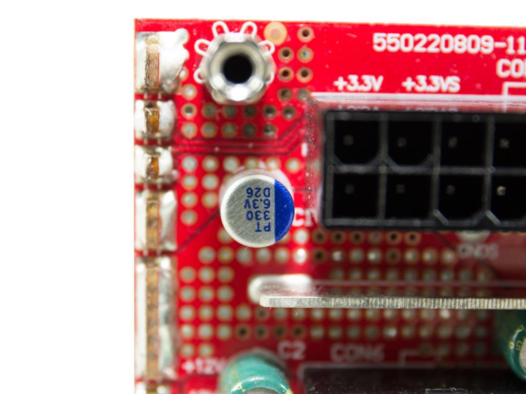
The APFC converter uses two Infineon IPP50R280CE fets and a STTH8R06D boost diode. The bulk cap is provided by Chemi-Con (450V, 390 uF, 105°C, KMR series, 2000h @ 105°C) and has a low capacity for this PSU, which will influence our hold-up test results.

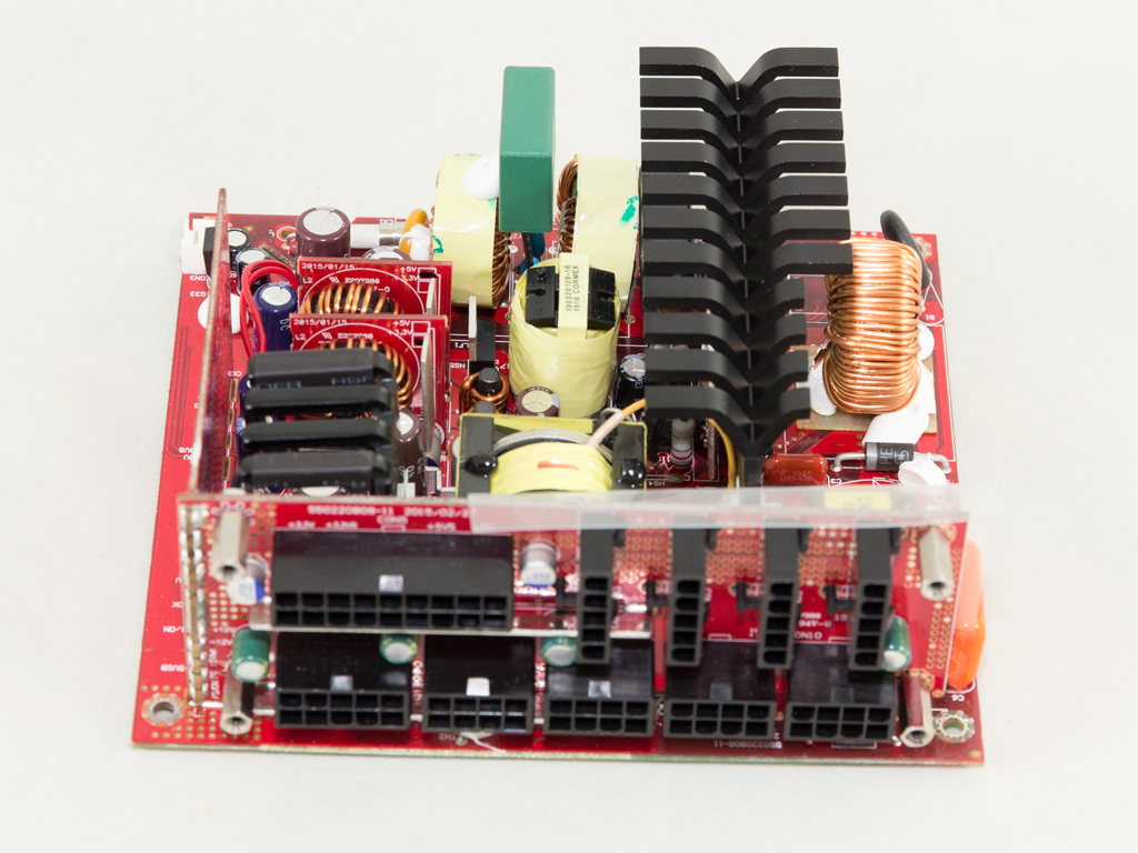
The PFC controller, a Champion CM6500TNX, and a CM03X Green PFC controller that supports it are installed on a small board residing right next to the APFC heatsink. The CM6500TNX includes an inrush-current-control function that measures how much inrush current is produced during start-up to protect the PSU and the whole system if too high.

The NTC thermistor is quite large; however, it doesn't do a good job in restricting inrush currents. Unfortunately, it isn't supported by a relay, although there is enough space for one. The V750 has such a relay, and given the small price difference to the V550, we expected the latter to have one as well. This relay would allow the NTC thermistor to cool down faster, all while increasing efficiency, so it shouldn't be missing.


The main switchers are two MagnaChip MDP18N50 fets. Exactly the same are used in the VSM550.

The standby PWM controller is an STR-A6069H IC, and the 5VSB rail is rectified by a PFR10V45CT SBR.

The +12V fets in the secondary side, four Infineon IPP041N04N G, are installed to a small heatsink with long-enough fins.


The secondary rails are generated by two small DC-DC converters. Each converter uses an APW7073 PWM controller and a single Infineon BSC050NE2LS fet.


The filtering caps are a mix of Nippon Chemi-Con, United Chemi-Con, and Suncon electrolytics. We also spotted a single Rubycon electrolytic, and two United polymer caps are on the mainboard. The VSM550 mostly used Teapo caps, which makes these a serious upgrade. However, this upgrade also significantly increases the price of the platform.


This 3D circuit is different from the one in the VSM550. The latter has a modified modular panel that is directly connected to the mainboard, which makes DC voltages pass through some wide traces and on to the modular sockets to minimize energy losses. In this case, an additional vertical daughter-board is used to transfer the rails to the modular sockets. This board replaces the power cables that normally transfer the power from the regulation circuits to the modular panel's sockets. You have to use very thick cables to minimize energy losses, which, while bulky, also restricts the amount of airflow in the secondary side. Wide PCB traces can also be shorter and have less impedance if properly designed, which means less energy goes to waste.


Several United polymer and a number of Suncon electrolytic caps further suppress ripple at the front of the modular PCB.


Soldering quality is very good in general, with short component leads. We only found two that aren't as nice since the traces had to be enhanced and copper wires were soldered onto them.


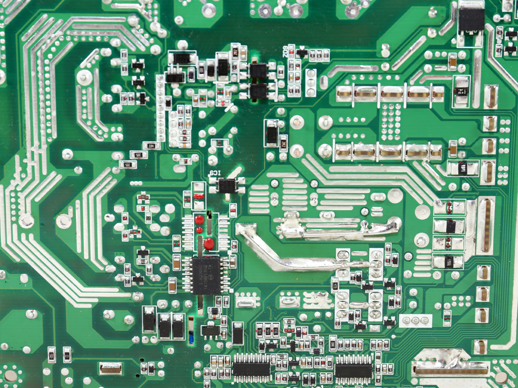
Like in the VSM550, the rear of the main PCB hosts several interesting ICs. These are a CM02X under the transient-filtering stage, which assists in minimizing energy loses on bleeding resistors, a Champion CM6901 as the LLC controller, the SITI PS223 protections IC, and a Silicon Labs Si8233BD isolator interface. We also found an SG30N04D fet on the solder side, which is most likely used by the 5VSB rail once the PSU has been switched on.

The fan uses a type of bearing we haven't come across thus far. It is a Looped Dynamic Bearing, and according to the schematics Cooler Master gave us, it looks to be an FDB (Fluid Dynamic Bearing) derivative. Cooler Master claims this bearing to last for 160,000 hours. The older VSM550 and other VSM units used a double ball-bearing fan, which was good, but not as good as this one, at least on papers. This LDB fan is also dust-proof, which will play a key role with its reliability.
May 5th, 2024 04:38 EDT
change timezone
Latest GPU Drivers
New Forum Posts
- AI Benchmark Alpha version 0.1.2 (2)
- Post your Speedometer 3.0 Score (38)
- Only some humans can see refresh rates faster than others, I am one of those humans. (114)
- What's your latest tech purchase? (20439)
- Is updating BIOS to beta versions a good idea if you have the most recent version installed but still face issues? (4)
- Strange system crashes out of nowhere, help (25)
- My Laptop is having issues with PL2 and EDP OTHER (10)
- Alphacool CORE 1 CPU block - bulging with danger of splitting? (95)
- Apparently Valve is giving refunds on Helldivers 2 regardless of hour count. Details inside. (37)
- PNY RTX 4070 Ti XLR8 OC - New worse BIOS/version? (107)
Popular Reviews
- Finalmouse UltralightX Review
- Meze Audio LIRIC 2nd Generation Closed-Back Headphones Review
- ASRock NUC BOX-155H (Intel Core Ultra 7 155H) Review
- Montech Sky Two GX Review
- Cougar Hotrod Royal Gaming Chair Review
- Upcoming Hardware Launches 2023 (Updated Feb 2024)
- Alienware Pro Wireless Gaming Keyboard Review
- HYTE THICC Q60 240 mm AIO Review
- AMD Ryzen 7 7800X3D Review - The Best Gaming CPU
- Logitech G Pro X Superlight 2 Review - Updated with 4000 Hz Tested
Controversial News Posts
- Intel Statement on Stability Issues: "Motherboard Makers to Blame" (240)
- Windows 11 Now Officially Adware as Microsoft Embeds Ads in the Start Menu (167)
- AMD to Redesign Ray Tracing Hardware on RDNA 4 (135)
- Sony PlayStation 5 Pro Specifications Confirmed, Console Arrives Before Holidays (117)
- AMD's RDNA 4 GPUs Could Stick with 18 Gbps GDDR6 Memory (114)
- NVIDIA Points Intel Raptor Lake CPU Users to Get Help from Intel Amid System Instability Issues (106)
- AMD Ryzen 9 7900X3D Now at a Mouth-watering $329 (104)
- AMD "Strix Halo" Zen 5 Mobile Processor Pictured: Chiplet-based, Uses 256-bit LPDDR5X (103)