 13
13
Corsair AX1200i 1200 W Review
Voltage Regulation & Efficiency »A Look Inside
Before reading this page we strongly suggest a look at this article, which will help you understand the internal components of a PSU better.


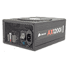
The new AX1200i is built by Flextronics, the same OEM that also made its predecessor and features a characteristic that distinguishes it from the rest of high-end PSUs. Instead of a PFC/PWM controller and a supervisor IC, it uses a Digital Signal Processor or DSP, which collects digital data from various components of the unit, analyzes everything and makes the proper adjustments to achieve the best possible performance. All the aforementioned procedures are executed must faster than in a traditional PSU that feeds the PFC/PWM controller with analog signals - voltage regulation even in highly dynamic loads is kept really tight and on top of that ripple and energy losses are greatly reduced. Except for the DSP, the AX1200i utilizes an LLC resonant along with a high-end topology in the primary side, consisting of six main switchers in total. With this unit, a new era to the PSU manufacturing is starting and we are pretty sure that, in the future, most PSU manufacturers will utilize similar designs.

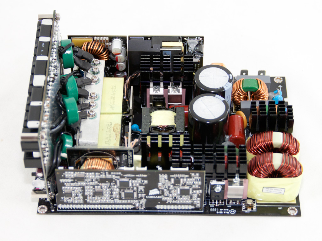
The AC receptacle incorporates a server grade EMI line filter which includes all necessary components, one X, two Y capacitors and a CM choke. We find more transient filtering components on the main PCB, namely three CM chokes, two X caps, two pairs of Y caps and an MOV (Metal Oxide Varistor), since a two stage transient filter is required in a desktop/server PSU. Finally, in order to completely remove the main PCB, we had to firstly remove a screw that is located right under the on/off switch. Thankfully, the removal of the latter was a pretty straightforward task.

The two parallel bridge rectifiers are cooled by a dedicated heatsink. Their model number is GSIB2560.


After the bridge rectifiers we find two PFC coils, which are an indication that, most likely, an interleaved PFC design, meaning two PFC converters operating in parallel with a phase difference among them, is utilized. A total of four IPA60R190E6 fets are used in the PFC along with two CREE C3D06060 boost diodes. The two parallel hold up caps are provided by Panasonic (470µF each or 940µF combined, 450V, 105°C).

The thermistor, responsible for the large inrush current protection and the relay that most likely isolates the thermistor from the circuit, once the startup phase finishes.

This heat sink holds the first primary switchers - two IPA60R125CP fets (Phase 1 LLC fets). In front of them we find the capacitors of the LLC resonant converter and behind them the intermediate Buck inductor.

This is the current transformer of the intermediate Buck circuit. In front of it we find a small heat sink with four fets. These are the Phase 2 LLC fets and as you can see, each one is protected by a metal shield which restricts EMI transmissions.


The control board that holds the DSP. This is, in other words, the central brain of the AX1200i that makes it so unique. On it we find a Silicon Labs Si8661BD six-channel digital isolator (located on the components side, so it is not visible on the photos above), several LM2902K quadruple operational amplifiers and a 56F8014 Freescale DSC (Digital Signal Controller) which, in essence, is a hybrid of microcontrollers and DSPs, combining the advantages of both. Its core is running at 32MHz and is rated at 32 Million Instructions per second (MIPS). It, among others, includes five PWM outputs and two 12-bit Analog-to-Digital Converters (ADCs) and can be programmed using the C programming language. The AX1200i doesn't, in fact, use a DSP but an even more advanced DSC. Besides the 56F8014 DSC, this board houses two Silicon Lab, fully integrated mixed-signal System-on-a-Chip, MCUs which also play the role of a DSP with higher clock speeds. Their model number is C8051F310 and C8051F380. Both use the same 8051 µC core but in the C8051F380, the core is clocked higher - the same MCU also includes a USB 2.0 function controller.

In front of the control board we find a small vertical daughter-board that holds the 5V DC-DC converter.


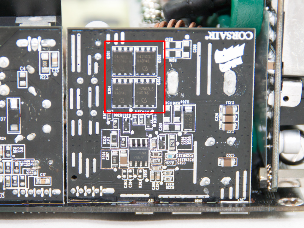
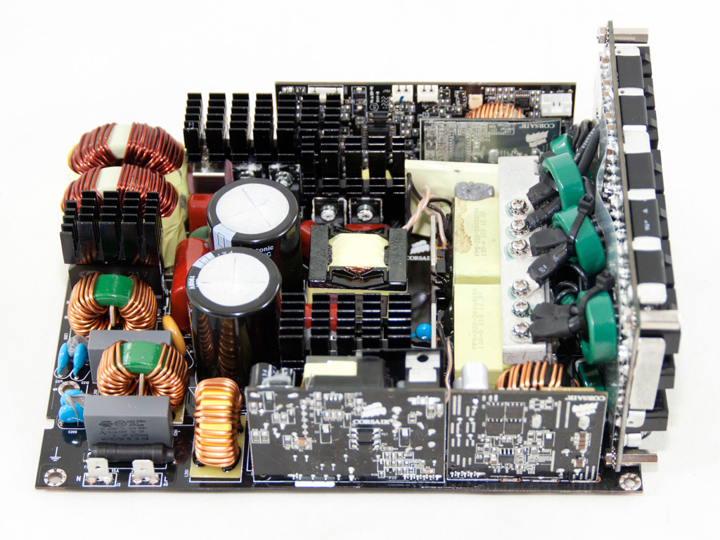
This is the 5VSB PCB and right next to it stands the 3.3V DC-DC converter. On the latter four IPB042N03L fets are used.
The two interleaved, parallel, main transformers hide the PCB which holds the fets that rectify +12V. On the same PCB four FPCAP polymer caps are visible. On the metal bar, above them, six thick and short wires transfer the +12V rail to the modular PCB. Some ferrite rings are used on the foregoing wires to suppress the high frequency EMI/RFI electronic noise.
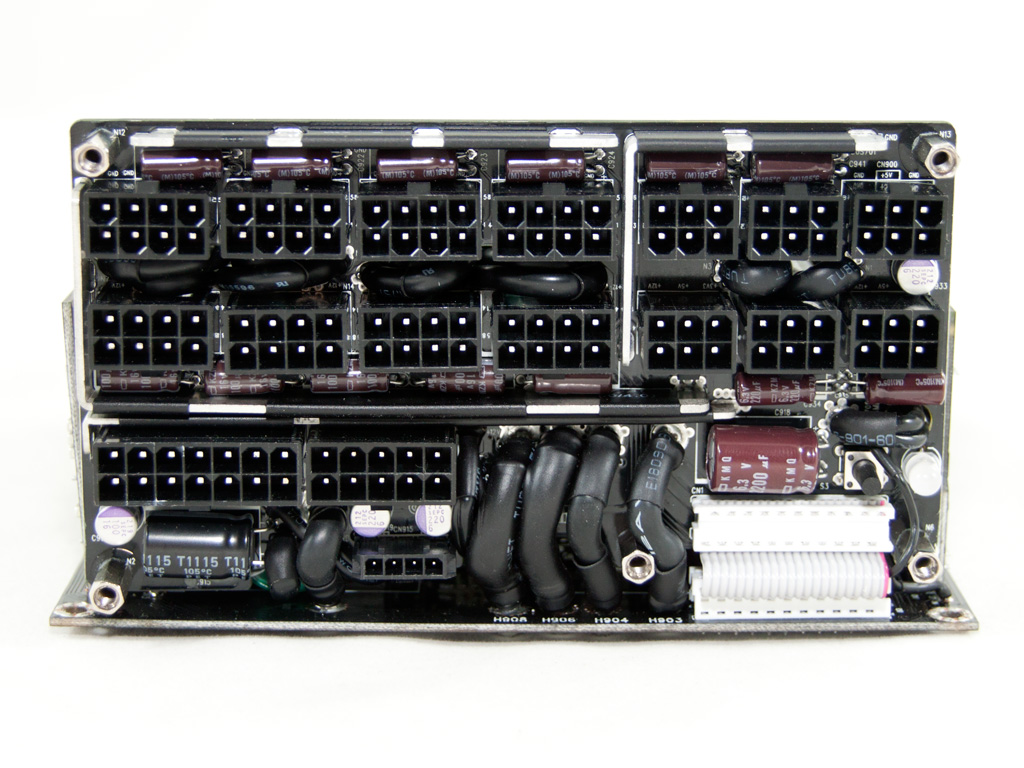


At the front side of the modular PCB we find many small, Chemi-Con, electrolytic caps that provide some extra ripple filtering along with a single Rubycon cap. There are also four small polymer caps provided by Sanyo (OS-CON).


The main PCB features impeccable soldering quality. Flextronics did an amazing job here.
All solder joints are perfect and we didn't even find a single long component lead. This PCB looks like a Picasso painting to the eyes of a PSU/electronics engineer.
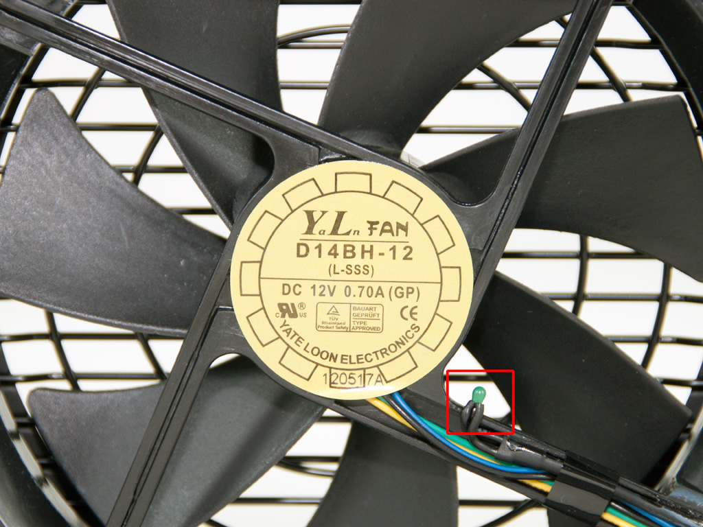

The fan that cools down the internals of the AX1200i is provided by Yate Loon Electronics and its model number is D14BH-12 (12V, 0.7 A, 2800 RPM, 140 CFM, 48.5 dBA). It is equipped with double ball-bearings for increased life time, compared to sleeved bearing ones. It is fairly quiet, since it is thermally controlled, and doesn’t spin at all at low loads. During our tests the highest speed it reached was 1800 RPMs. Finally, a thermistor is attached on it and the second connector is for this component. Both the fan and the thermistor are connected to the control board of the PSU.
May 3rd, 2024 07:46 EDT
change timezone
Latest GPU Drivers
New Forum Posts
- Your PC ATM (34541)
- Free Games Thread (3771)
- Microsoft Did It Again! Beware Of Bugged Update KB5034441 (181)
- fastest usb cable /transfer (3)
- Ryzen Owners Zen Garden (7289)
- PNY 4070 Ti Super XLR8 (0)
- Rare GPUs / Unreleased GPUs (1879)
- Looking for recommendations to upgrade the GPU (41)
- Just for lolz, Post your 3DMark2001SE Benchmark scores! (84)
- Firmware RTX 3060 mobile (1)
Popular Reviews
- HYTE THICC Q60 240 mm AIO Review
- ASRock NUC BOX-155H (Intel Core Ultra 7 155H) Review
- Montech Sky Two GX Review
- Meze Audio LIRIC 2nd Generation Closed-Back Headphones Review
- Ugreen NASync DXP4800 Plus Review
- Upcoming Hardware Launches 2023 (Updated Feb 2024)
- Team Group T-Force Vulcan ECO DDR5-6000 32 GB CL38 Review
- MOONDROP x Crinacle DUSK In-Ear Monitors Review - The Last 5%
- AMD Ryzen 7 7800X3D Review - The Best Gaming CPU
- Logitech G Pro X Superlight 2 Review - Updated with 4000 Hz Tested
Controversial News Posts
- Intel Statement on Stability Issues: "Motherboard Makers to Blame" (231)
- Windows 11 Now Officially Adware as Microsoft Embeds Ads in the Start Menu (167)
- Sony PlayStation 5 Pro Specifications Confirmed, Console Arrives Before Holidays (117)
- AMD's RDNA 4 GPUs Could Stick with 18 Gbps GDDR6 Memory (114)
- NVIDIA Points Intel Raptor Lake CPU Users to Get Help from Intel Amid System Instability Issues (106)
- AMD "Strix Halo" Zen 5 Mobile Processor Pictured: Chiplet-based, Uses 256-bit LPDDR5X (103)
- AMD Ryzen 9 7900X3D Now at a Mouth-watering $329 (103)
- TechPowerUp Hiring: Reviewers Wanted for Motherboards, Laptops, Gaming Handhelds and Prebuilt Desktops (93)