 19
19
Corsair CX Series Modular CX600M 600 W Review
Voltage Regulation, Hold-up Time & Inrush Current »A Look Inside & Component Analysis
Before reading this page, we strongly suggest a look at this article, which will help you understand the internal components of a PSU much better. Our main tool for the disassembly of the PSU is a Thermaltronics TMT-9000S soldering and rework station. It is of extreme quality and is equipped with a matching de-soldering gun. With such equipment in hand, breaking apart every PSU is like a walk in the park!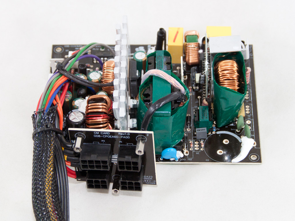

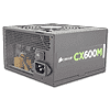
The unit's OEM is CWT, and they have a great collaboration going with Corsair. The unit is based on CWT's DSAII platform, but carries several significant upgrades. It, for starters, uses a non-standard PCB layout, which allows for increased performance. Corsair also used an upgraded standby PWM controller to provide increased efficiency in standby and to make the CX600M ErP 2013 ready. On top of that, four SBRs are used for +12V regulation instead of the two that the reference platform has, which translates into lower temperatures and higher efficiency at increased loads, and better voltage regulation. Finally, the CX600M features transformers of a higher quality and a Japanese bulk (hold-up) capacitor instead of the Taiwanese one that the stock DSAII platform uses. All in all, Corsair made quite a few changes indicative of their active part in the design process; they don't just stick to a different label with the units they sell.
The transient filter starts at the AC receptacle with a pair of Y caps, and the cables that transfer power to the main PCB are wrapped around a ferrite bead for EMI reduction. On the main PCB, we find the other components of the transient filter: two pairs of X and Y caps, two CM chokes, and an MOV (Metal Oxide Varistor) for protection against power surges.

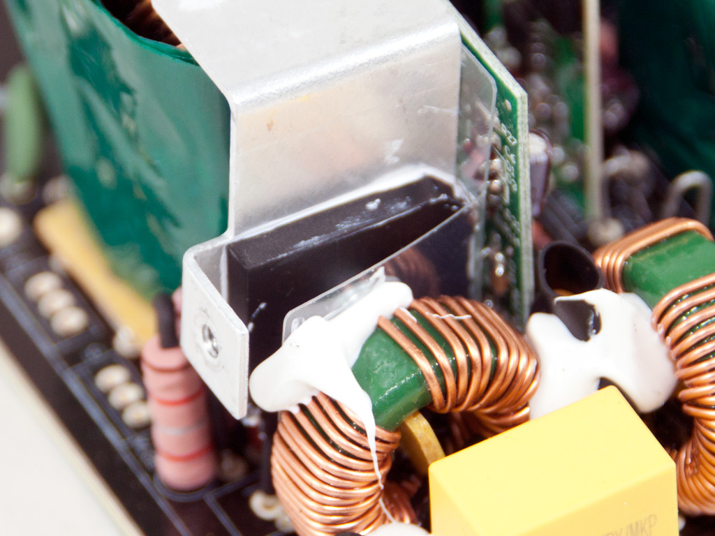
The single bridge rectifier is bolted to a dedicated heatsink, and we didn't feel like removing the heatsink to only identify the bridge rectifier.


Two K18A60V fets for which we couldn't find any relevant info are used in the APFC circuit, along with an STTH8S06D boost diode. Matsushita/Panasonic provides the bulk cap (400 V, 270 μF, 85°C).

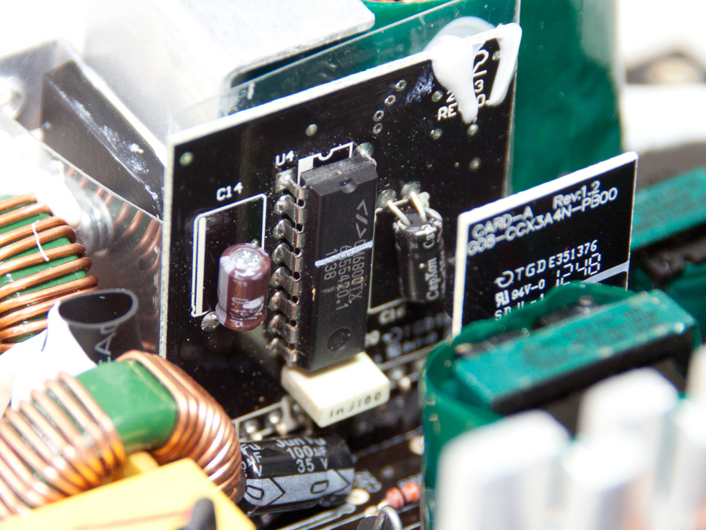

The main switchers are two STF14NM50N fets. The PFC/PWM controller is the famous Champion CM6800 IC and is installed on the vertical daughter-board.


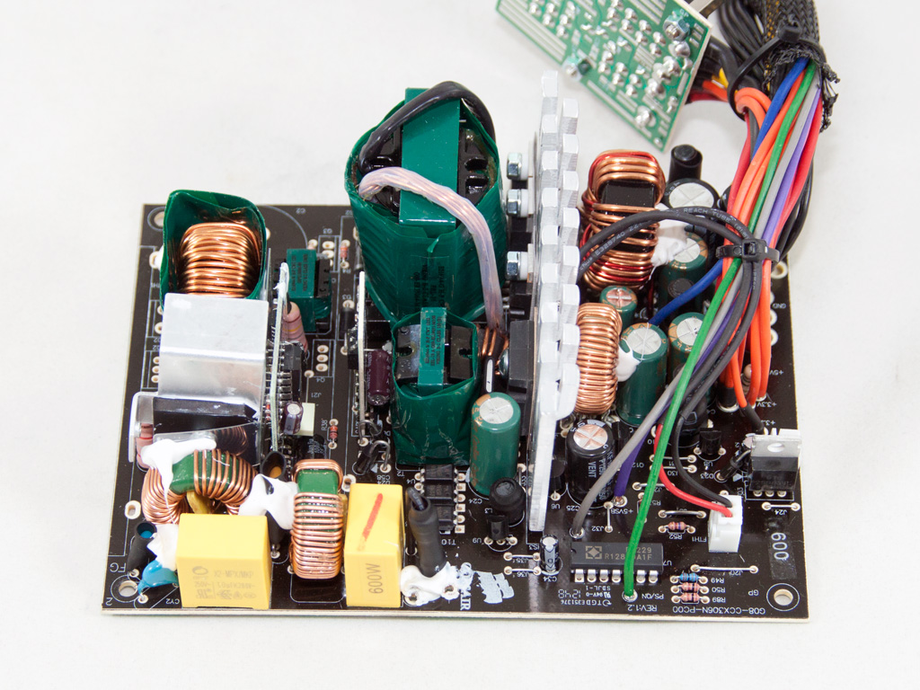
We find the 5VSB fet and the standby PWM controller, which provides compliance with the newest ErP Lot 6 2013 directive, on this small daughter-board.


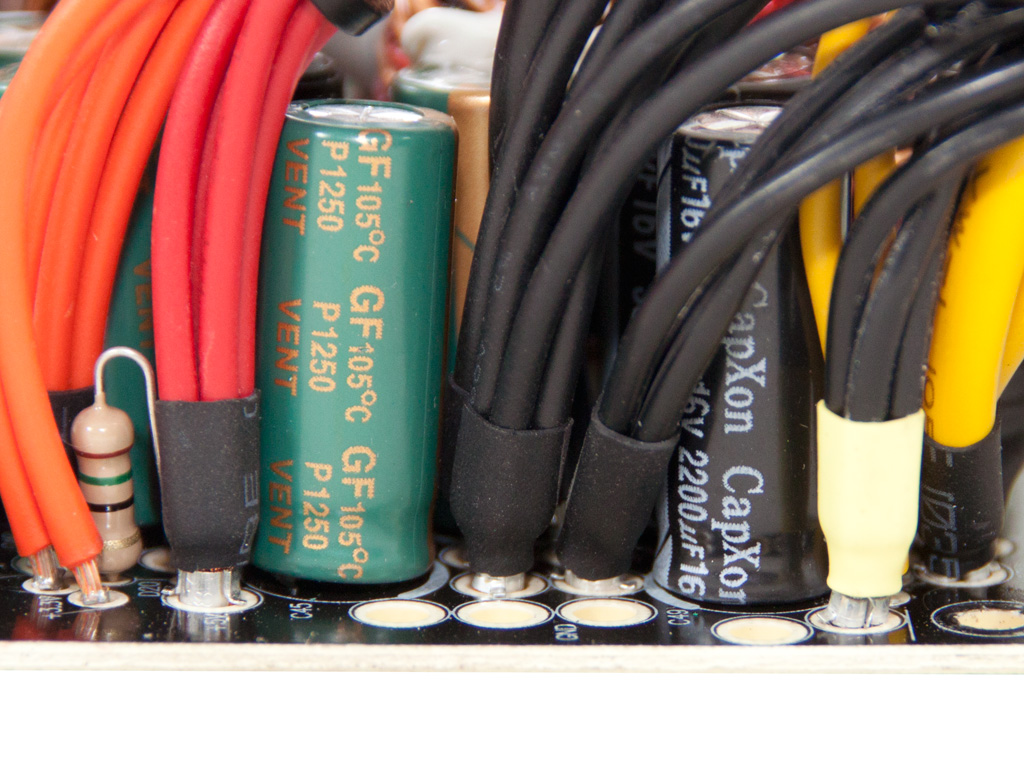
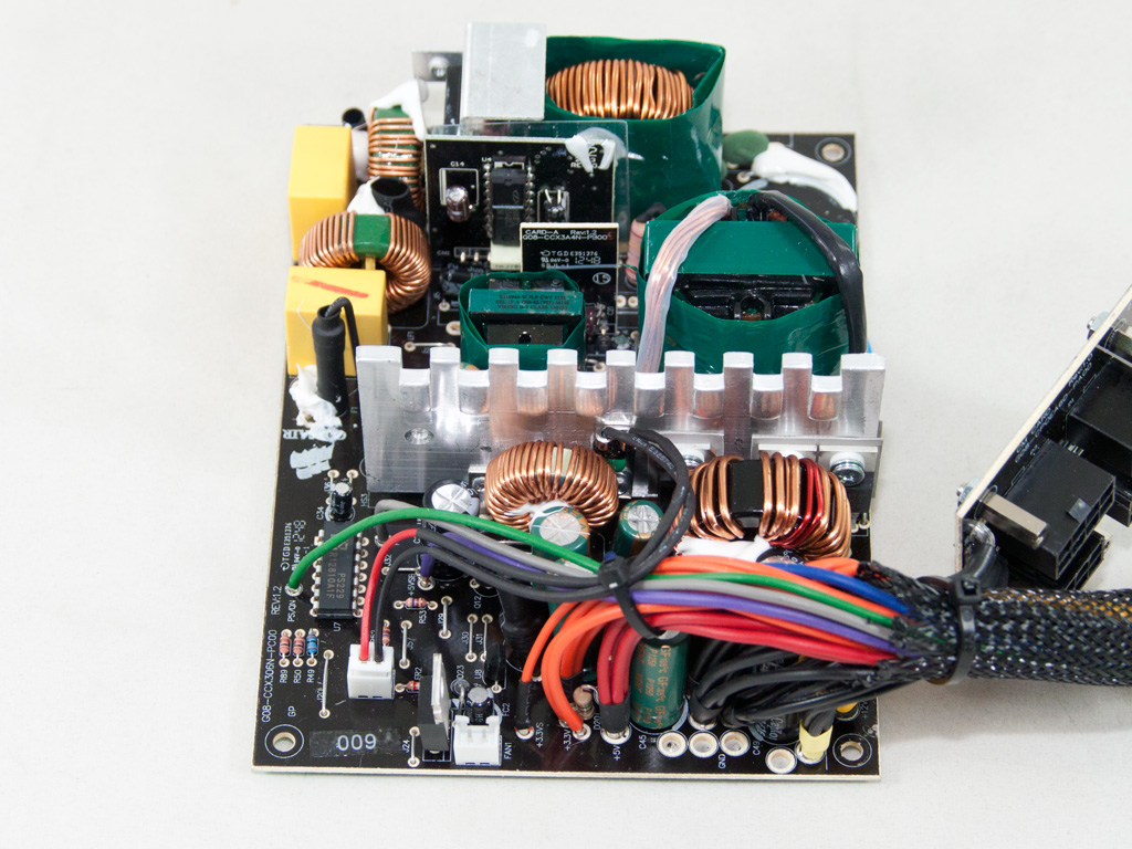
The only two toroidal chokes in the secondary side indicate that a group regulated scheme is being utilized. On top of that, a passive design is utilized, so the +12V rail is regulated by Schottky Barrier Diodes (SBRs) and, more specifically, four PFR40V60CTs. Two STPS3045CT SBRs rectify the 5V rail, and the 3.3V rail uses a single STPS40L45CW. Finally, all filtering caps in the secondary side are from CapXon and are rated at 105°C. We would like to see caps of a higher quality here, at least Teapo ones, but doing so would apparently raise the unit's overall cost significantly.
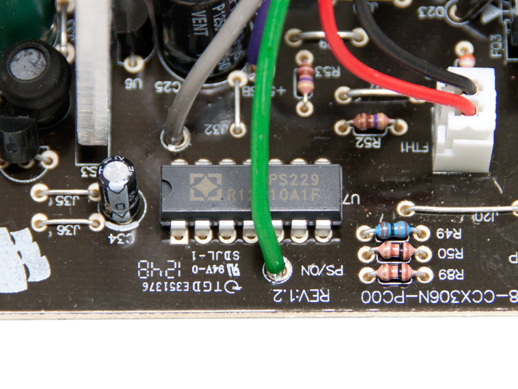
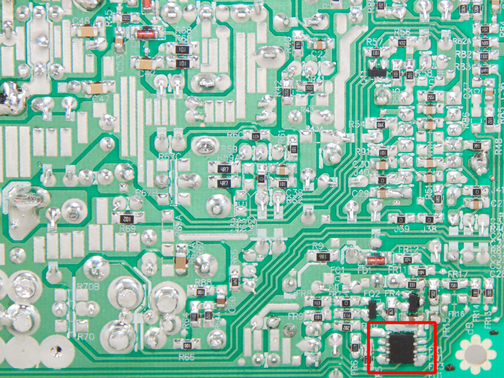
The supervisor IC is installed on the main PCB and is a SITI PS229. It supports OCP for a single +12V rail and includes all the other protection features except for OTP.

These optocouplers provide the necessary electrical isolation between the primary and the secondary side.
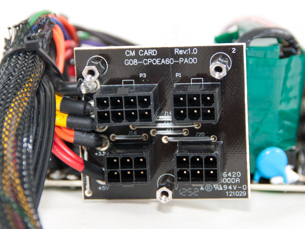

The modular PCB is small, since it only holds four sockets.

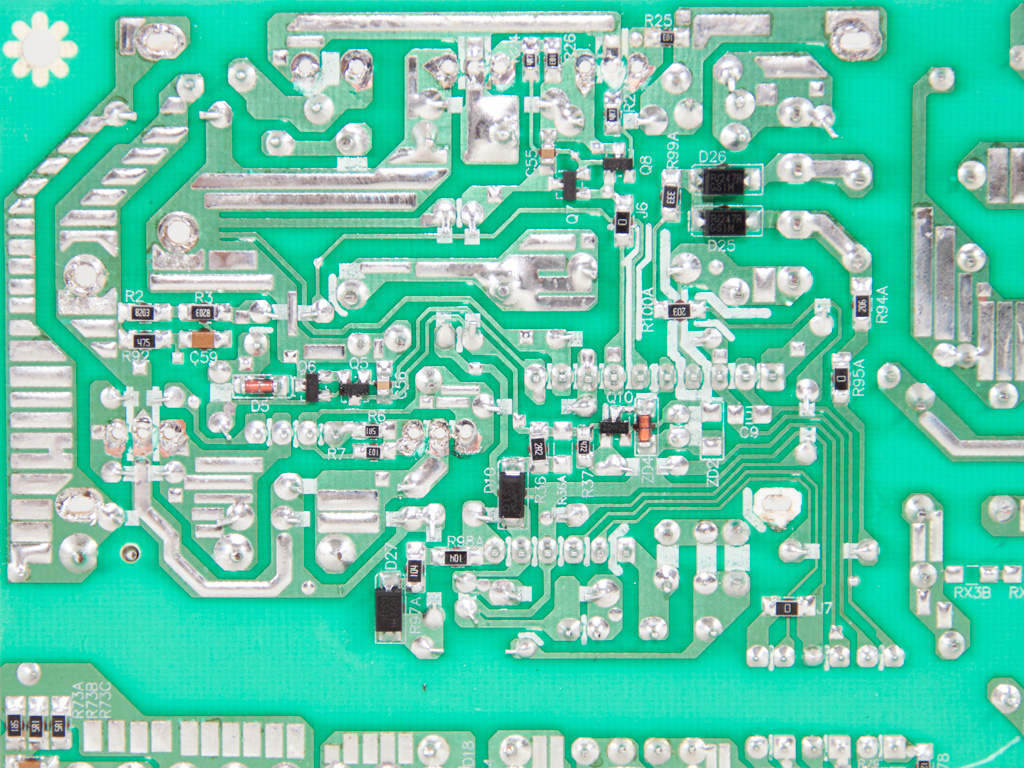
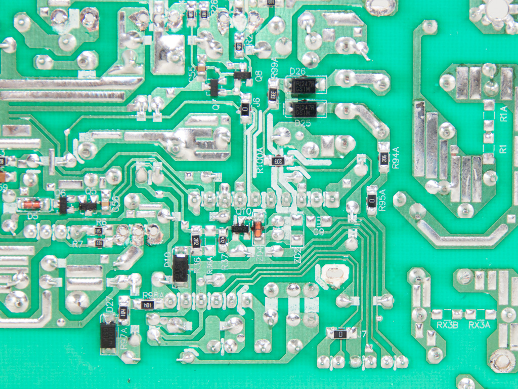

The main PCB features decent soldering quality that is surely above the average. However, the PCB is single-sided to keep production cost down.
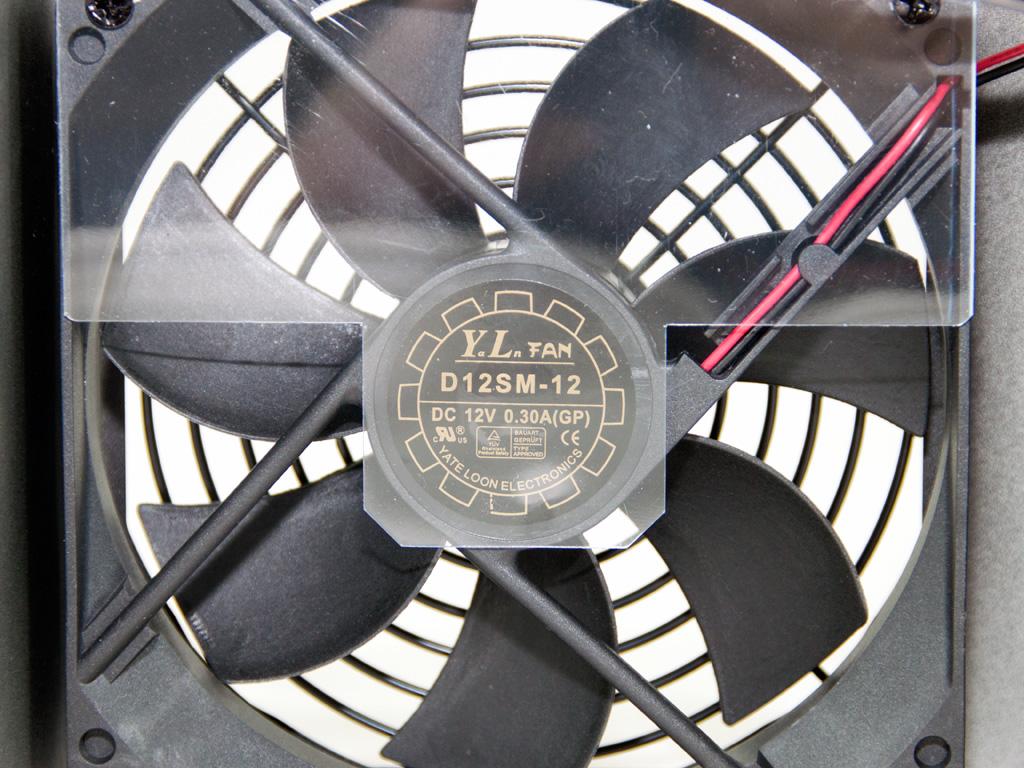
The cooling fan is provided by Yate Loon, and its model number is D12SM-12 (120 mm, 12 V, 0.3 A, 70.5 CFM, 1650 RPM). It has a sleeve-bearing, so it won't last as long as a ball-bearings fan, but we can't ask for more at this price range.
May 1st, 2024 20:22 EDT
change timezone
Latest GPU Drivers
New Forum Posts
- 2019 LTSC vs 2021 LTSC (4)
- Would you guys be ok with 70C idle temp on NVME storage. (21)
- 7900 XTX Seriously lacking (100)
- Creating custom XMP profile for DDR4 (82)
- What are you playing? (20567)
- 7800XT Issue , amdflash bios (2)
- Old high quality PSU, or semi-old mid-quality PSU? (36)
- Post your 7zip 23.01 scores (15)
- Arctic MX-6 shelf life is just a couple months? (68)
- Core PL1 + GPU PL1 + Ring EDP OTHER (16)
Popular Reviews
- Ugreen NASync DXP4800 Plus Review
- HYTE THICC Q60 240 mm AIO Review
- Montech Sky Two GX Review
- Upcoming Hardware Launches 2023 (Updated Feb 2024)
- MOONDROP x Crinacle DUSK In-Ear Monitors Review - The Last 5%
- Team Group T-Force Vulcan ECO DDR5-6000 32 GB CL38 Review
- AMD Ryzen 7 7800X3D Review - The Best Gaming CPU
- Thermalright Phantom Spirit 120 EVO Review
- ASUS Radeon RX 7900 GRE TUF OC Review
- FiiO K19 Desktop DAC/Headphone Amplifier Review
Controversial News Posts
- Intel Statement on Stability Issues: "Motherboard Makers to Blame" (213)
- Windows 11 Now Officially Adware as Microsoft Embeds Ads in the Start Menu (158)
- Sony PlayStation 5 Pro Specifications Confirmed, Console Arrives Before Holidays (117)
- AMD's RDNA 4 GPUs Could Stick with 18 Gbps GDDR6 Memory (109)
- NVIDIA Points Intel Raptor Lake CPU Users to Get Help from Intel Amid System Instability Issues (106)
- AMD "Strix Halo" Zen 5 Mobile Processor Pictured: Chiplet-based, Uses 256-bit LPDDR5X (103)
- TechPowerUp Hiring: Reviewers Wanted for Motherboards, Laptops, Gaming Handhelds and Prebuilt Desktops (91)
- AMD Ryzen 9 7900X3D Now at a Mouth-watering $329 (90)