 11
Corsair HX1000i Shift Crystal Review
Test Methodology »Internals
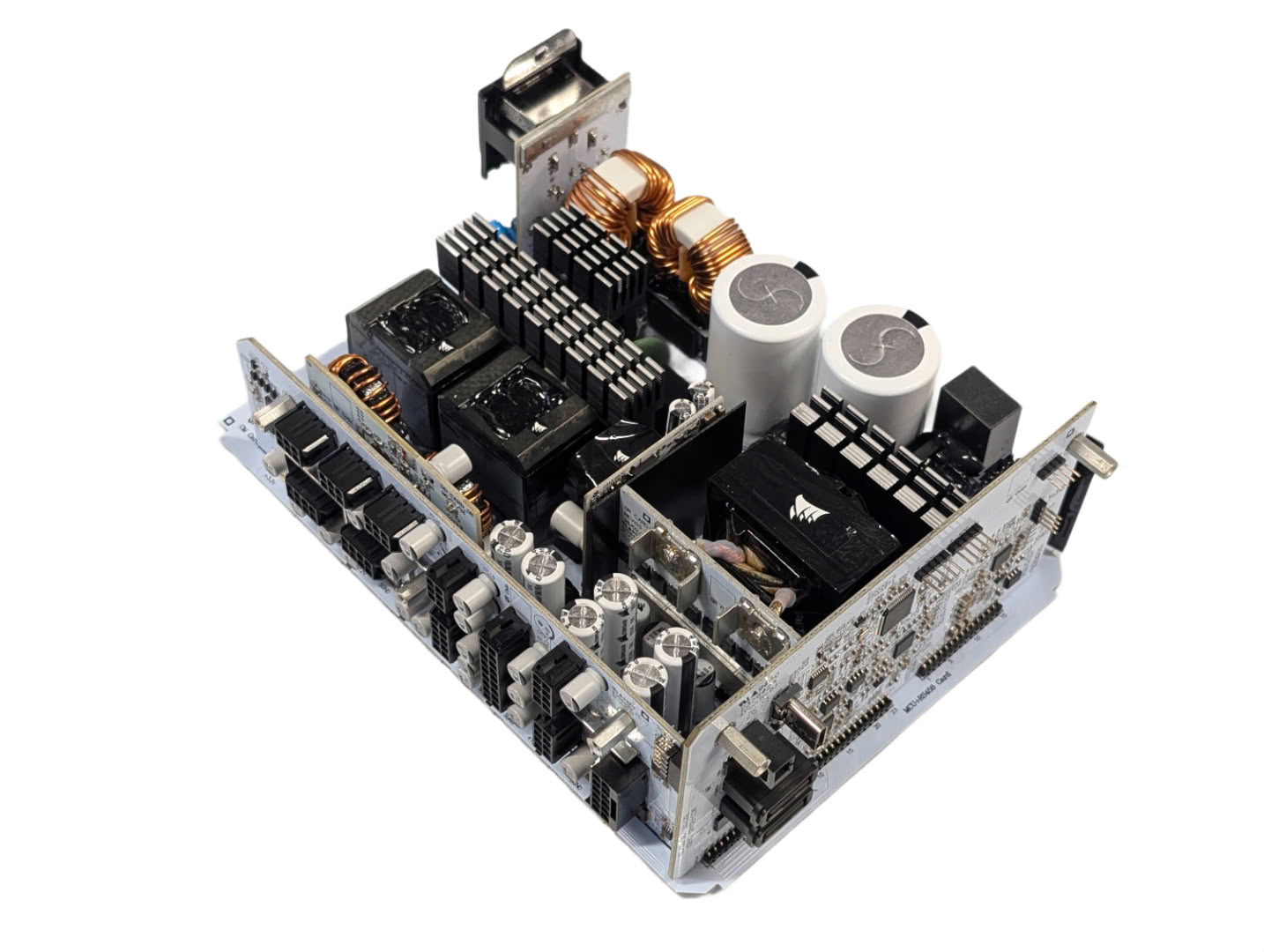
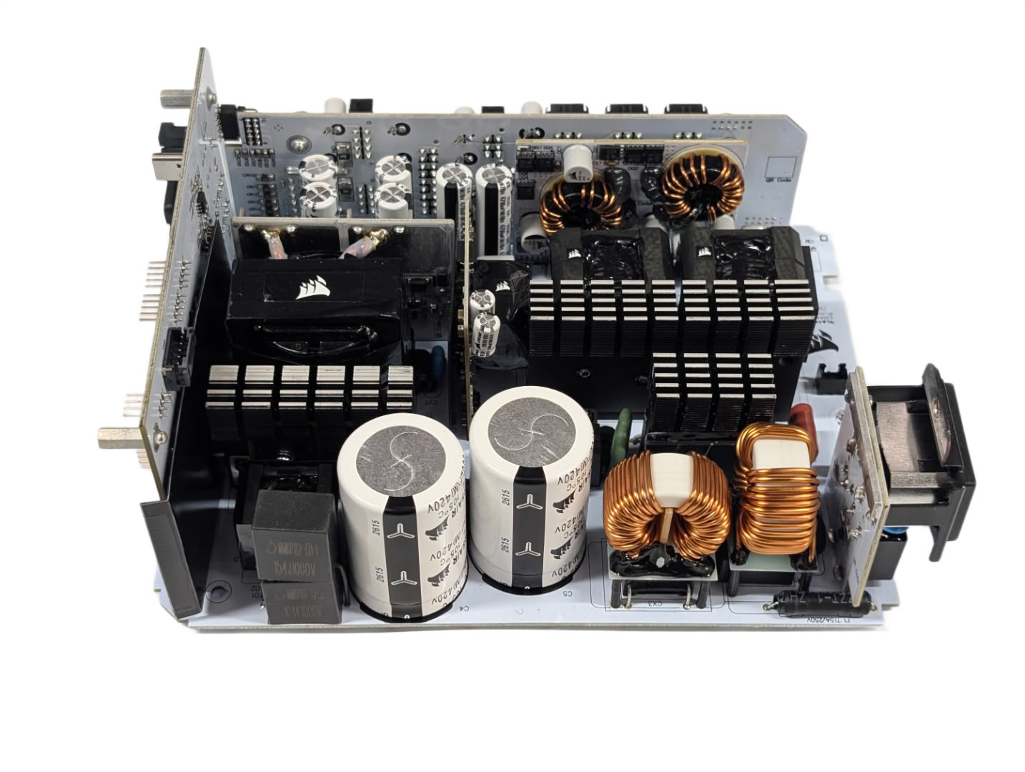

This is a stunningly clean PCB layout. It almost looks like it was designed specifically for the clear case, with only the large components laid out neatly on the top, with no sprawling cables or messy adhesive, and all the SMD components confined to upright boards keeping the top surface clear. This is the exact same layout as the original HX1000i Shift though, so it in fact hasn't been done like this just for this clear case variant; but the change to an all-white PCB was.

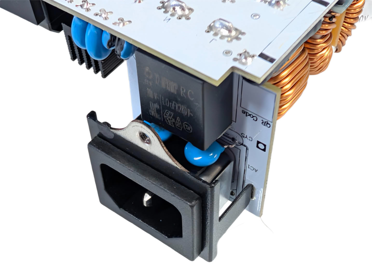
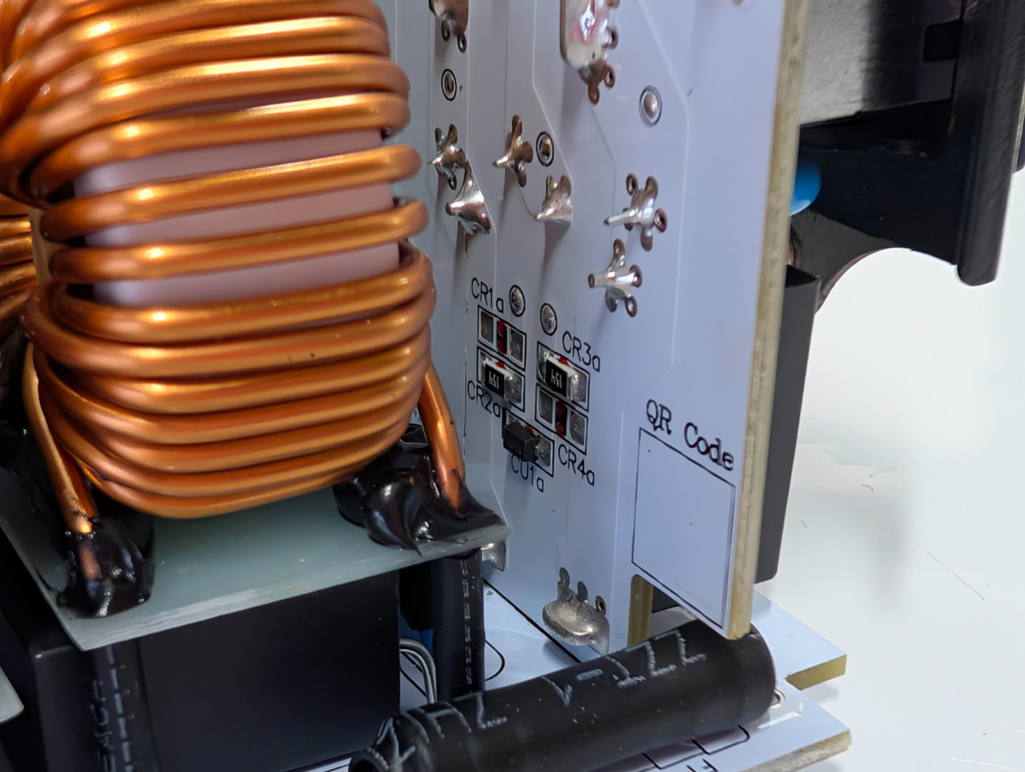
The mains input connector is on its own upright PCB, which also has a pair of Y caps and an X cap neatly fitted right by the connector itself. On the back there are also a few SMD components to discharge the capacitors when mains power is removed.

The mains power switch connects here, and it doesn't directly break the incoming AC mains voltage. Instead, it is a logic level signal that disables the PSU digitally.
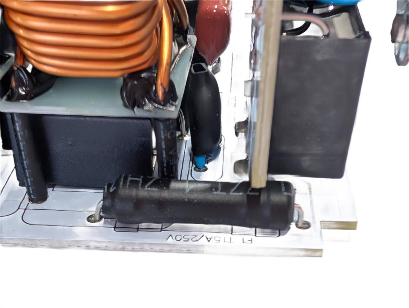
The first things power sees coming into the main PCB are a MOV and the main fuse.

Additional Y caps are fitted right by the mains connector board, and there are a pair of X caps hiding neatly under a pair of CM chokes.


A pair of full bridge rectifiers are mounted to their own finned heatsink towards the center of the board. The thermal paste application isn't particularly neat, but these parts aren't really visible through the case.

Inrush suppression happens after rectification, by this thermistor which is bypassed by the adjacent relay.

The bulk caps have had custom Corsair branded sleeves applied, both for improved aesthetics by making them white, but also to flip the print upside-down so that when the PSU is installed the text is the right way around. As a result we cannot confirm the exact brand or model of caps used, but it would be safe to assume they haven't deviated from the earlier HX1000i Shift, in which case they will be a Nippon Chemi-Con 560 uF 420 V model rated for 2000h @ 105 °C, alongside a Rubycon 470 uF 420 V model, also rated for 2000h @ 105 °C.


Active power factor correction should be very effective as this is handled digitally by a UCD3138A controller. This drives a pair of IPW60R099P6 MOSFETs that work in conjunction with two IDH08G65C6 boost diodes. These are all mounted to their own finned heatsink.
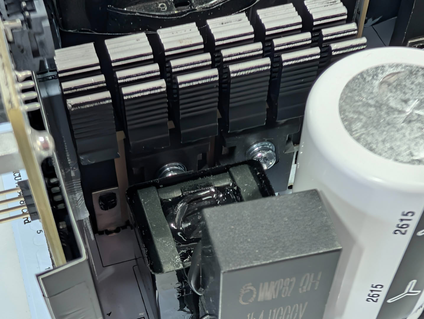
The main switching MOSFETs also have a heatsink to themselves. These are a pair of IPW60R099P6 MOSFETs in the larger TO-247AC package.

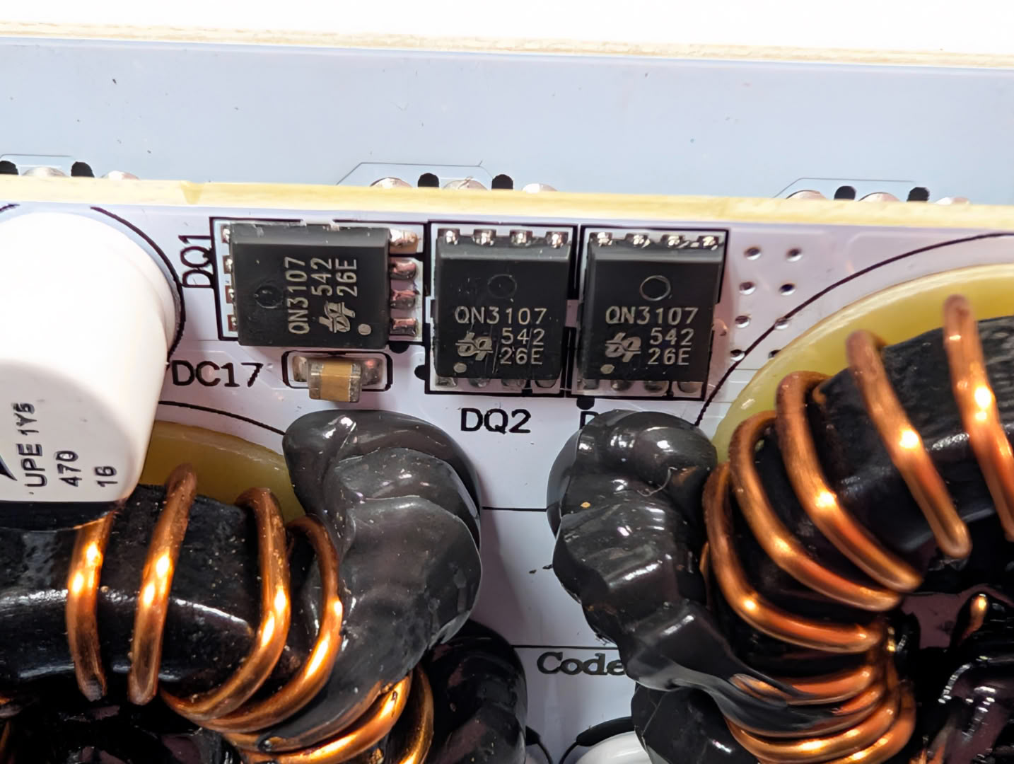

The minor rails use analogue DC-DC conversion from the main 12 V rail, and are generated here on this upright daughter board by QN3107M6N MOSFETs and on-board inductors, driven by a uP3861P IC.


The 12 V rail is generated here. There is an upright board connected directly to the transformer which houses ten Infineon BSC014N04LS MOSFETs. This is a thick board with extra thermal mass and fins added, which will also reduce trace resistance. One of the transformer legs to this board has a touch less solder than I would like to see; for the strongest and most reliable connection, the solder should flow all around the wire onto the metal plate, but it looks as though not enough heat was soaked into the plate so it didn't flow around fully. Even the smaller filter capacitors here have Corsair-branded sleeves.


The underside of the board is also extremely neat and clean, with only a handful of active components mounted here, including the 12 V MOSFET driver.
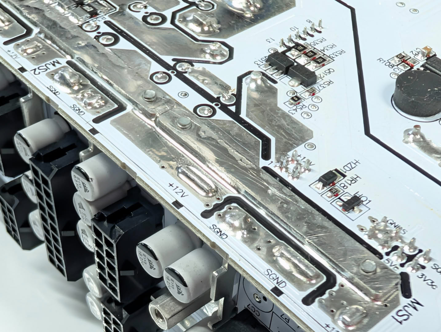
The connector board is soldered very solidly, and the traces carrying high current power have been bolstered with metal bars to reduce voltage drop.

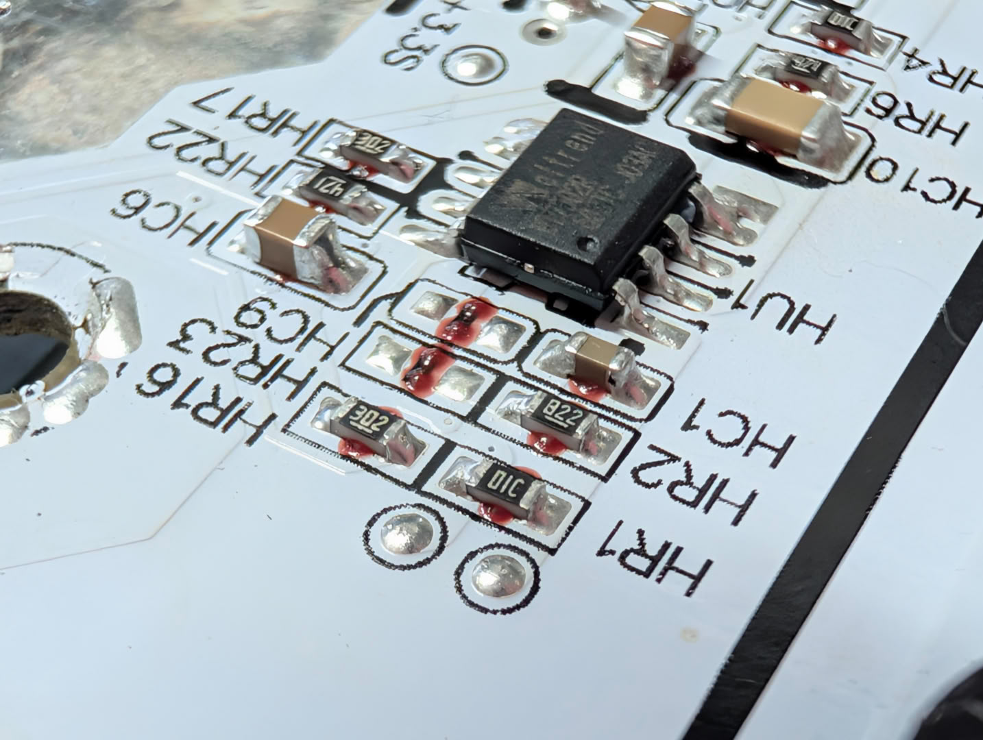
The soldering quality throughout is very neat, as you would expect from a model where the PCB is going to be on show. The SMD components are adhered with glue before the flowing process, to ensure they don't shift around.
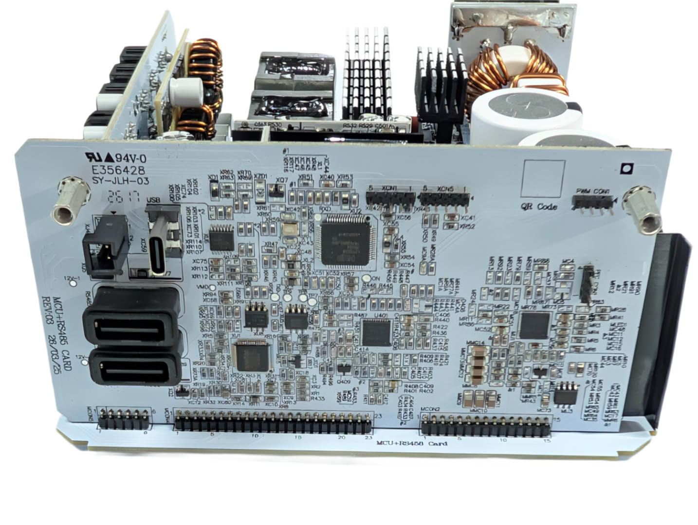
The board at the front of the PSU contains almost all the control circuitry that drives each of the main power stages, deals with monitoring and protection, fan control, and lighting and communication over USB to the iCUE software. This is also a very neatly done PCB, which is good as it is very much on show through the clear case.
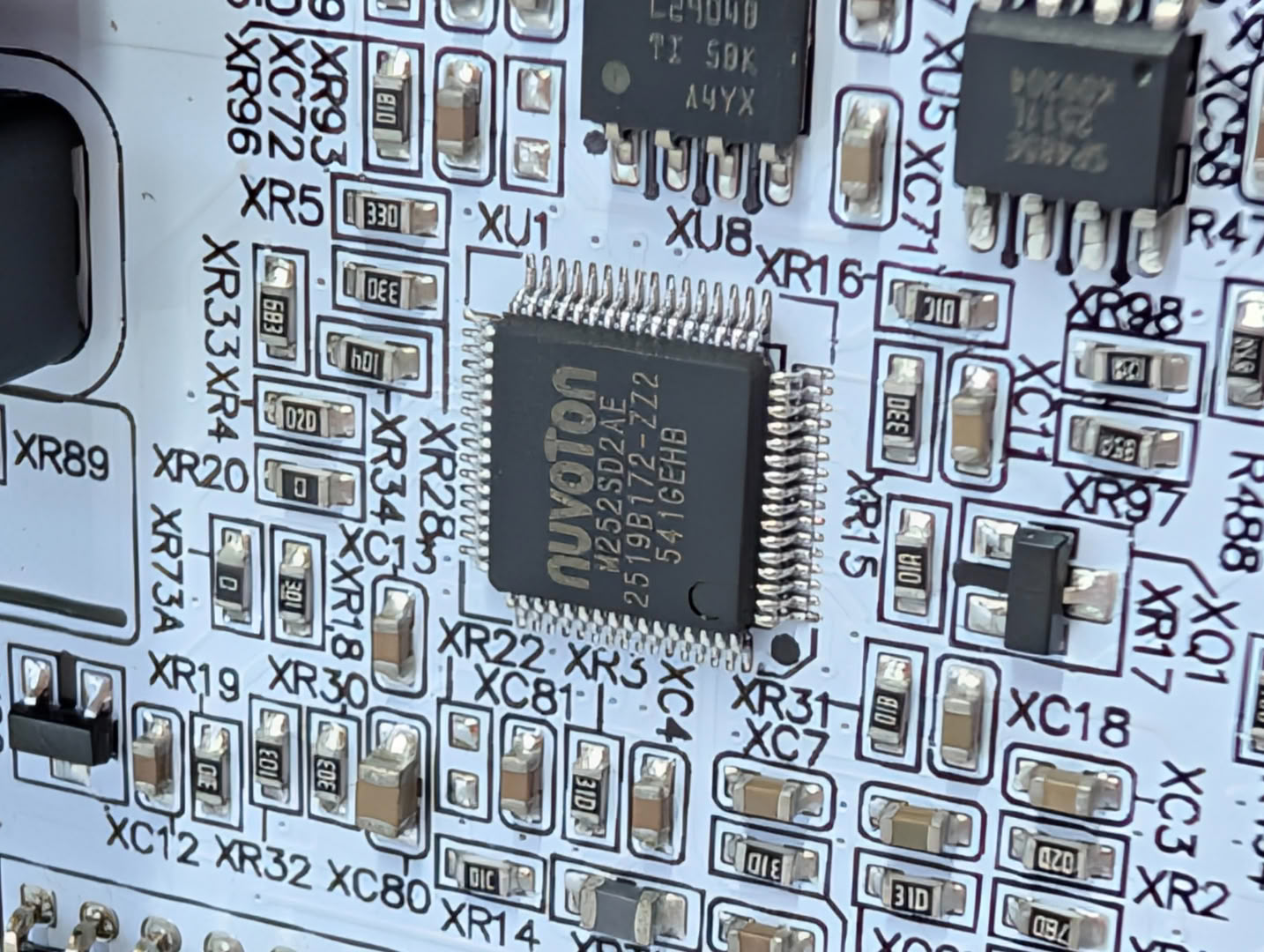

There are a pair of microcontrollers deployed in this PSU; a NuMicro M252SD2AE using Arm Cortex-M23, and a larger NXP LPC5528 Arm Cortex-M33. Using microcontrollers allows for extremely precise programming of protection modes and thresholds, shut-off behavior with software reporting, and highly optimized switching modes based on load, temperature, or other factors. This new Crystal model has Corsair's new PinProtect+ that monitors the 12V-2x6 connector, which will require some processing power, especially when it comes to reporting status and faults over USB, and even changing the LED colors if a fault is detected.

These aforementioned UCD3138A digital ICs maintain tight control over APFC and resonant conversion, to yield high efficiency that can adapt to varying conditions.

The connector board is neat and there are plenty of filter capacitors placed alongside the connectors themselves. They are smaller size ports than those found on other PSUs, which helps with layout and offers more space for filter caps and bus bars.
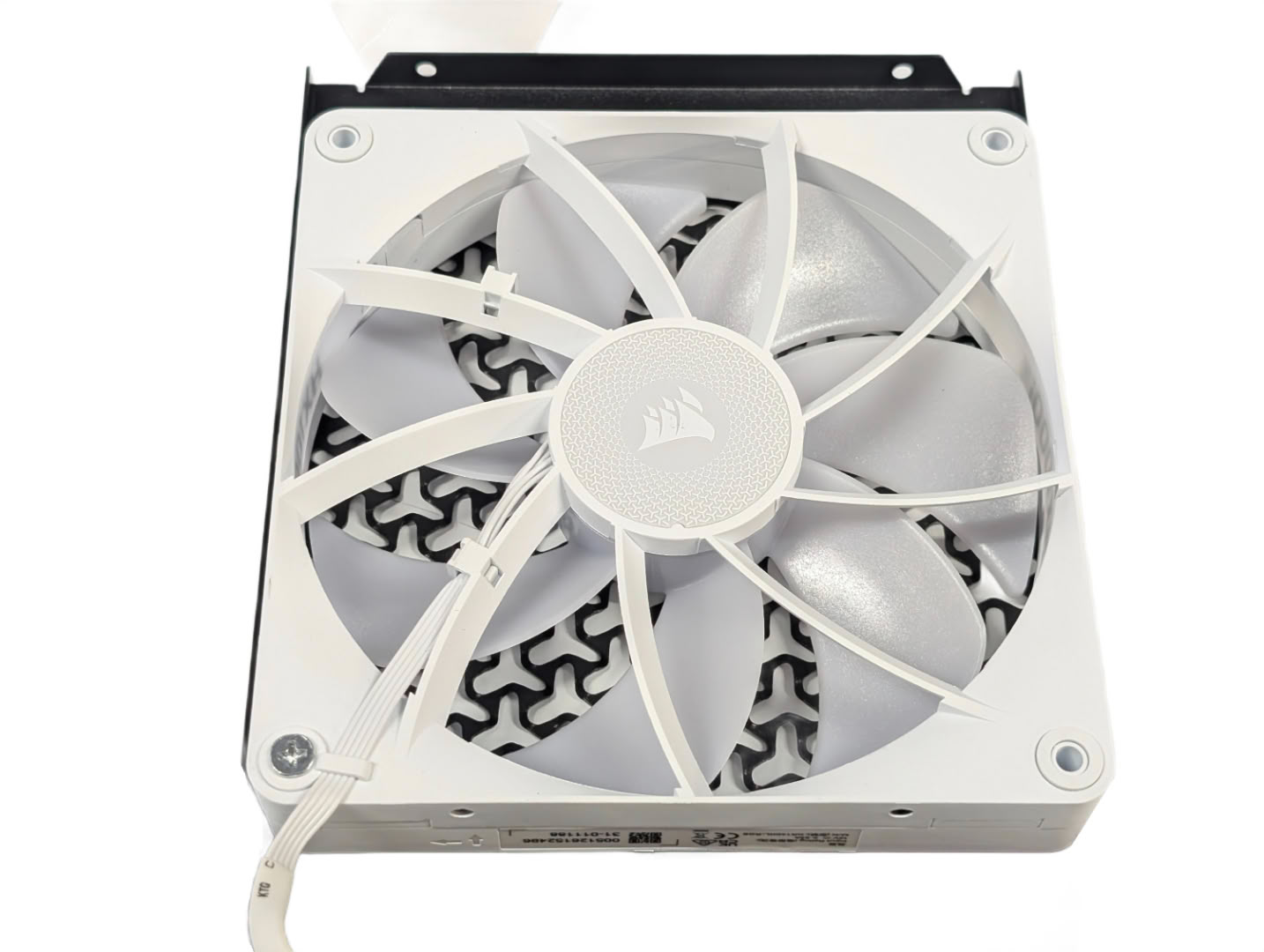

The fan used is a NR140HL-RGB, which is a modified RGB variant of the non-RGB NR140P used previously. It uses a magnetic dome bearing, Corsair's refined implementation of magnetic levitation bearing technology, which has a number of benefits over a fluid dynamic bearing; lower starting friction so lower initial speeds can be run, improved longevity as there are no lubricants or oils to dry up over time, and immunity to different mounting orientations. The NR140P is a solid high static pressure performer, so we should expect the same from the adapted RGB version used here.
Nov 12th, 2026 13:54 PST
change timezone
Latest GPU Drivers
New Forum Posts
- budget home NAS – X79, X99 or another platform? (145)
- I won't download games that are larger than 30–40 GB. (97)
- Your PC ATM (36409)
- What are you playing? (26211)
- When you could finally run Crysis maxed out? (60)
- [Community Benchmark] MrH OpenCL Benchmark 2.0e (Windows Only – CPU & GPU) (0)
- DTS DCH Driver for Realtek HDA [DTS:X APO4 + DTS Interactive] (2810)
- Windows 11 General Discussion (7725)
- WarpCoreBench scores! (16)
- Classic Blizzard games (WarCraft 1-2, Diablo 1-2, StarCraft 1) (6)
Popular Reviews
- AMD Zen 6 Technical Deep Dive
- Upcoming Hardware Launches 2027 (Updated Nov 2026)
- NZXT C1200 Platinum Review
- XPG NIMBUS PLUS Review - Mid-range Chair With Strong Competitors
- NZXT H7 RGB+ Review
- Corsair HX1000i Shift Crystal Review
- Montech King 95 3D PRO Review
- NZXT H5 Review
- Phantom Blade Zero Performance Benchmark Review - 35 GPUs Tested
- Gigabyte Z890I Aorus Ultra Review
TPU on YouTube
Controversial News Posts
- NVIDIA Co-Founder and CEO Jensen Huang Officially Resigns (222)
- OpenAI CEO Argues Home PCs Waste the World's Limited DRAM Supply (152)
- NVIDIA Launches Investigation Into Jensen Huang's Relationship With Suspected Chinese Spy (136)
- Intel "Raptor Lake Next" 16-Core and 20-Core CPUs Surface (130)
- Legendary Game Studio BioWare Shuts Down Following EA Layoffs (104)
- Dell CEO Says the Memory Shortage Will Get Worse in 2027 (95)
- NVIDIA GeForce RTX 50-Series Scheduled for up to $500 Price Hike This Week (89)
- Modder Fits RTX 5090 With Four 8-Pin Connectors, Halving Current per Wire (80)