 15
CPS PCCooler YS1200 Review
Test Methodology »Internals
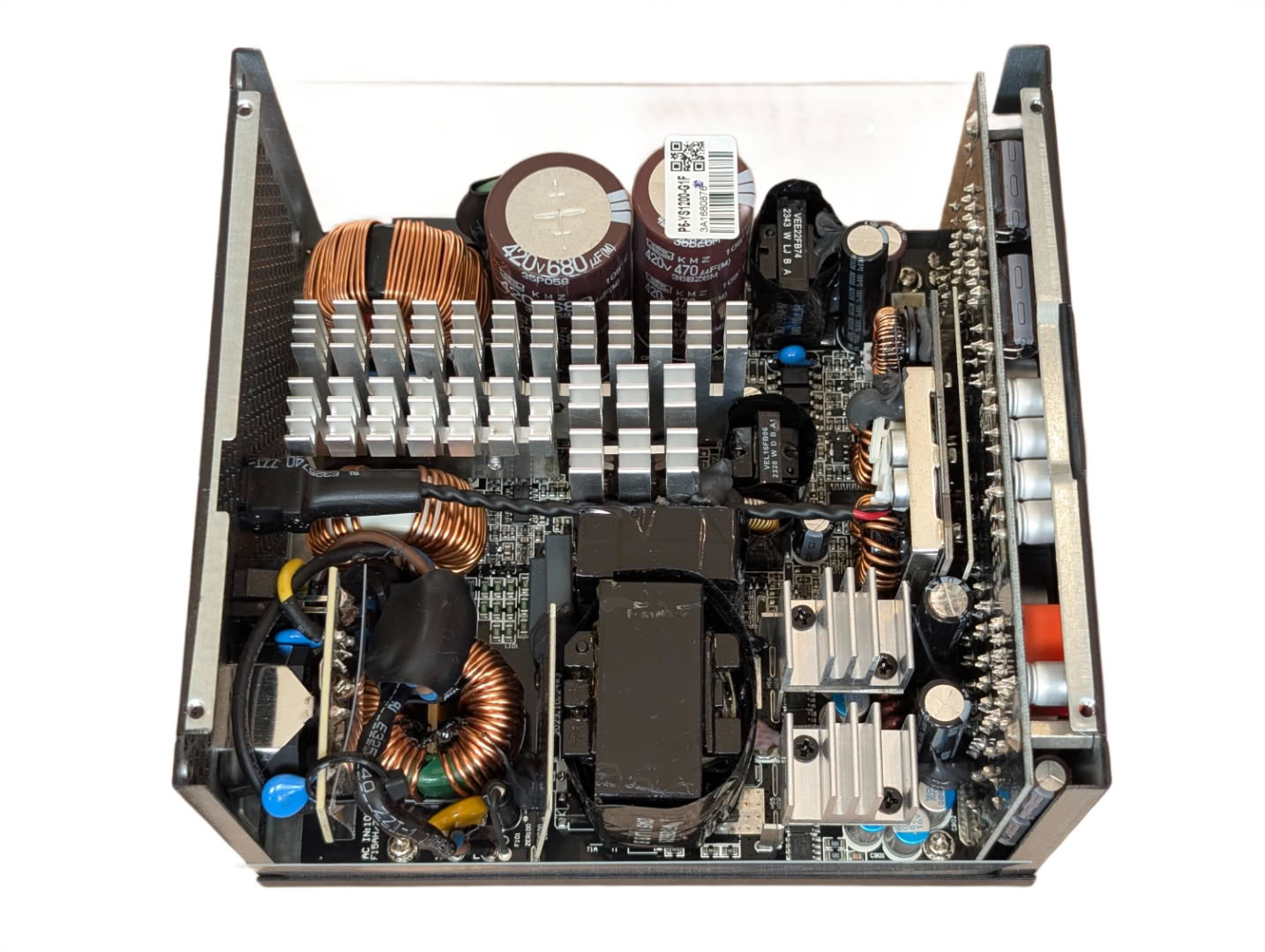

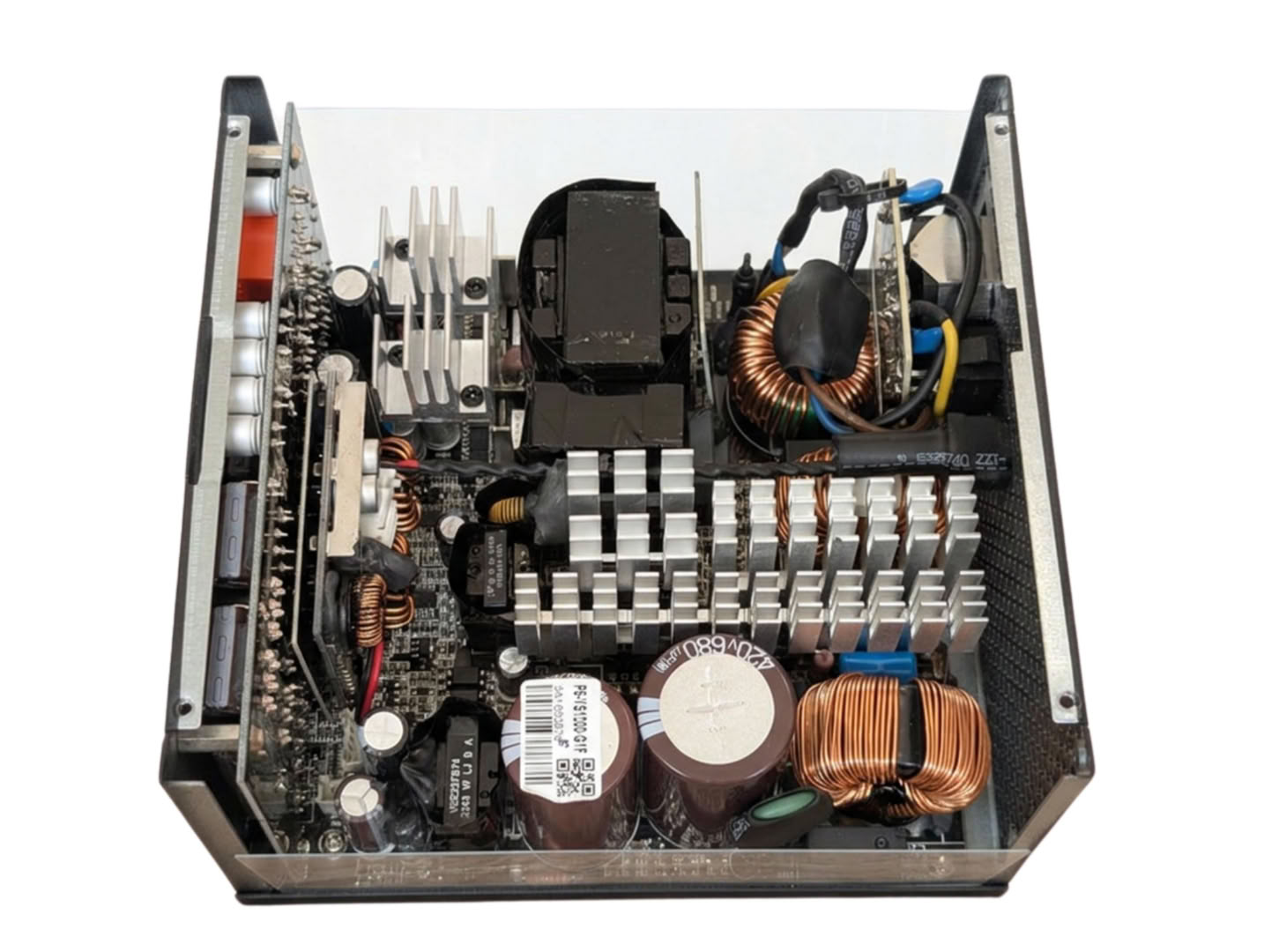
At first glance inside, we are presented by caps and fins. This is quite a healthy amount of power for this form factor so naturally it is packed tightly with attention to thermal dissipation.
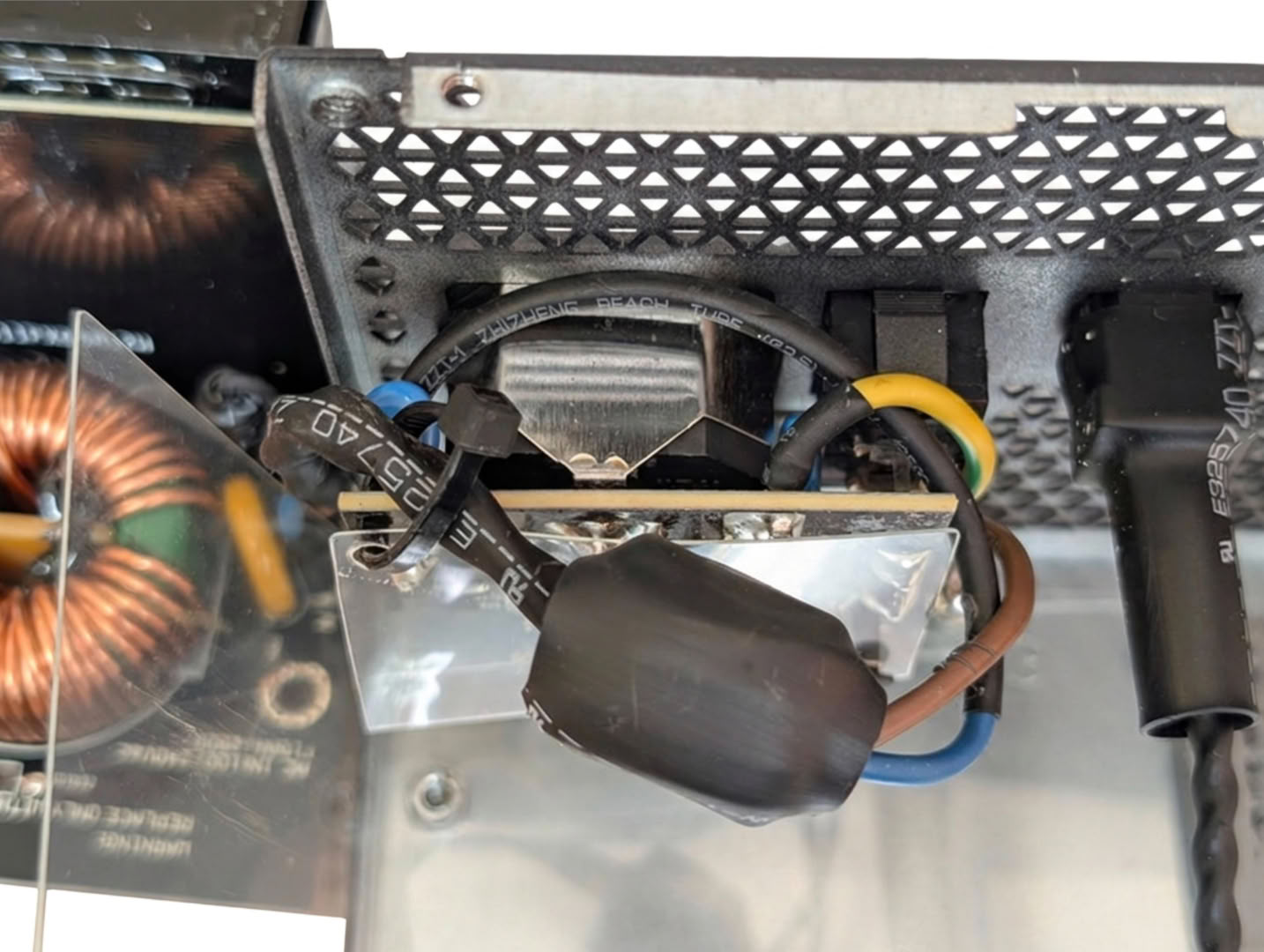
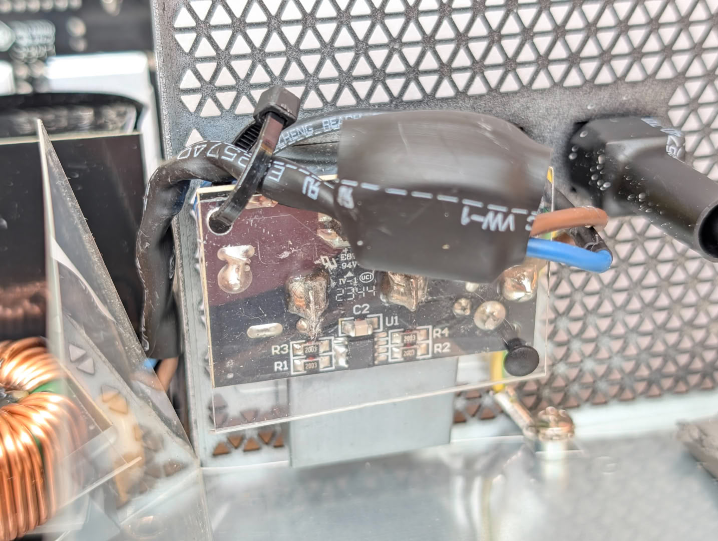
Directly soldered to the mains connector are a pair of Y caps, and an X cap, including a small PCB to discharge it once mains power is removed. A ferrite core is included along the cable to the board for noise isolation.
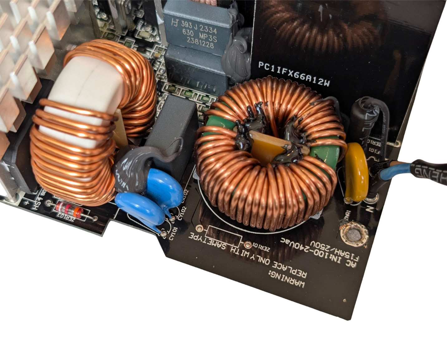
Coming into the main PCB, there are two more Y caps and an X cap, the MOV, a fuse, and a pair of CM chokes.
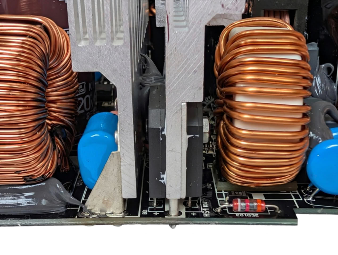
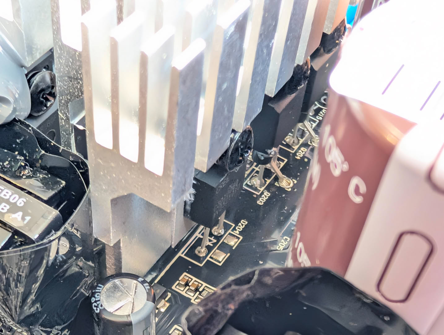
Further along the board, there are a pair of full bridge rectifiers sandwiching a heatsink, which is also shared by the active PFC components.
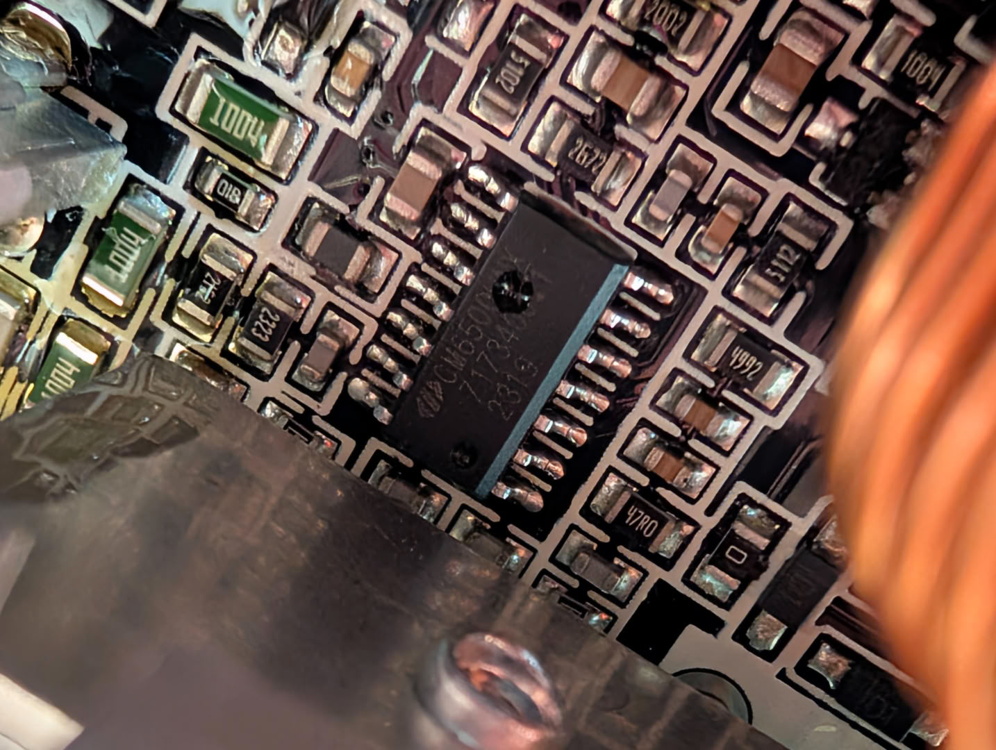
Active PFC is handled by the tried and tested Champion CM6500 controller, which is driving two Toshiba TK31E60W MOSFETs, with a CREE C3D10060A boost diode.
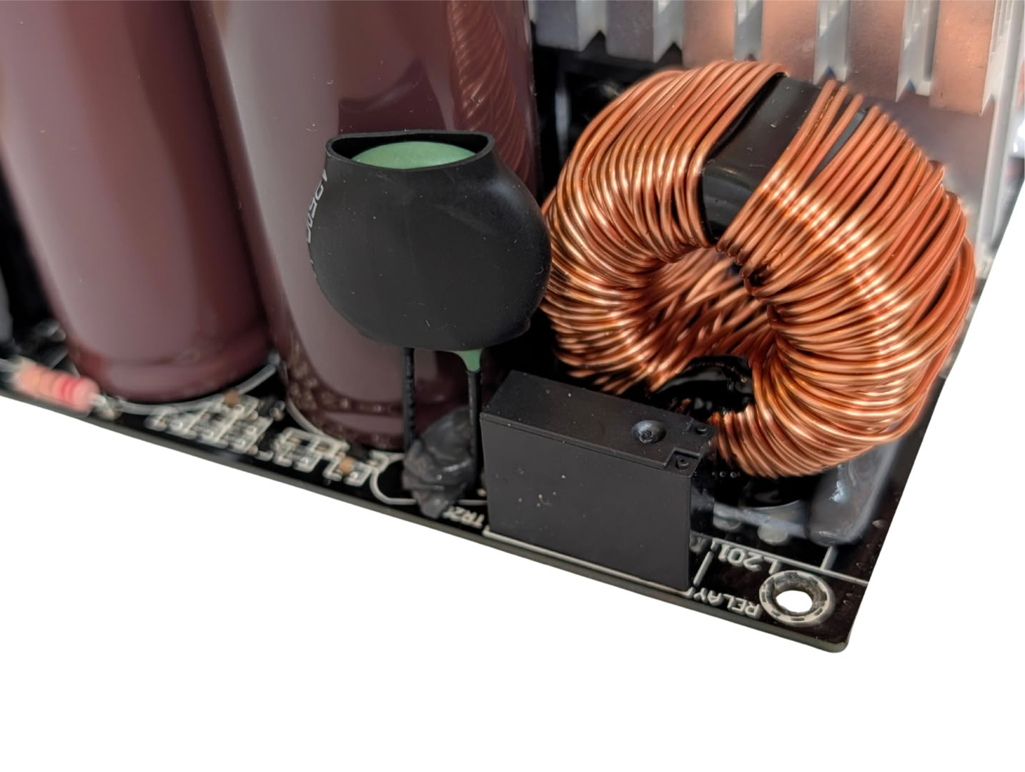
Inrush suppression is handled after rectification here, by means of a 5 ohm NTC Thermistor (MF72-5D20L) which is bypassed by a relay once the bulk caps are sufficiently charged.
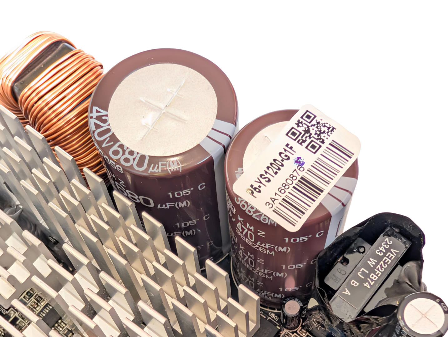
The pair of Nippon Chemi-Con bulk capacitors provide a total capacitance of 1150 uF. These are rated for 2000 h @ 105°C.
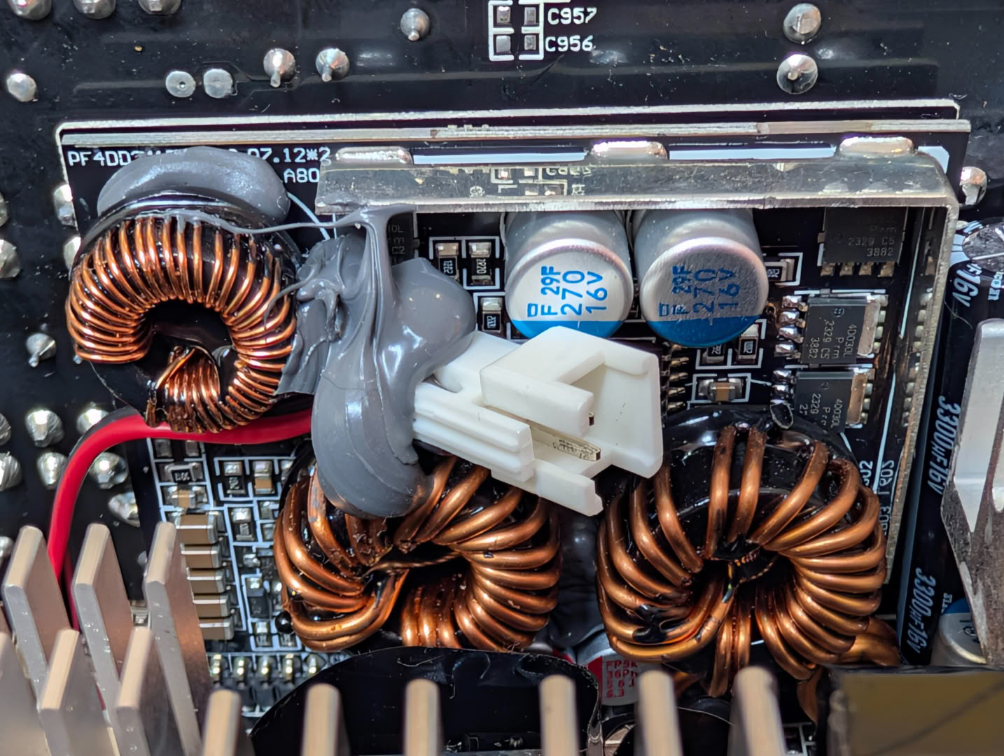
Like seen in most other supplies, the auxiliary rails are generated on an upright daughterboard here using DC-DC conversion. In this instance we have an ANPEC APW7159C PWM controller driving six Nexperia PSMN4R0-30YLD MOSFETs.
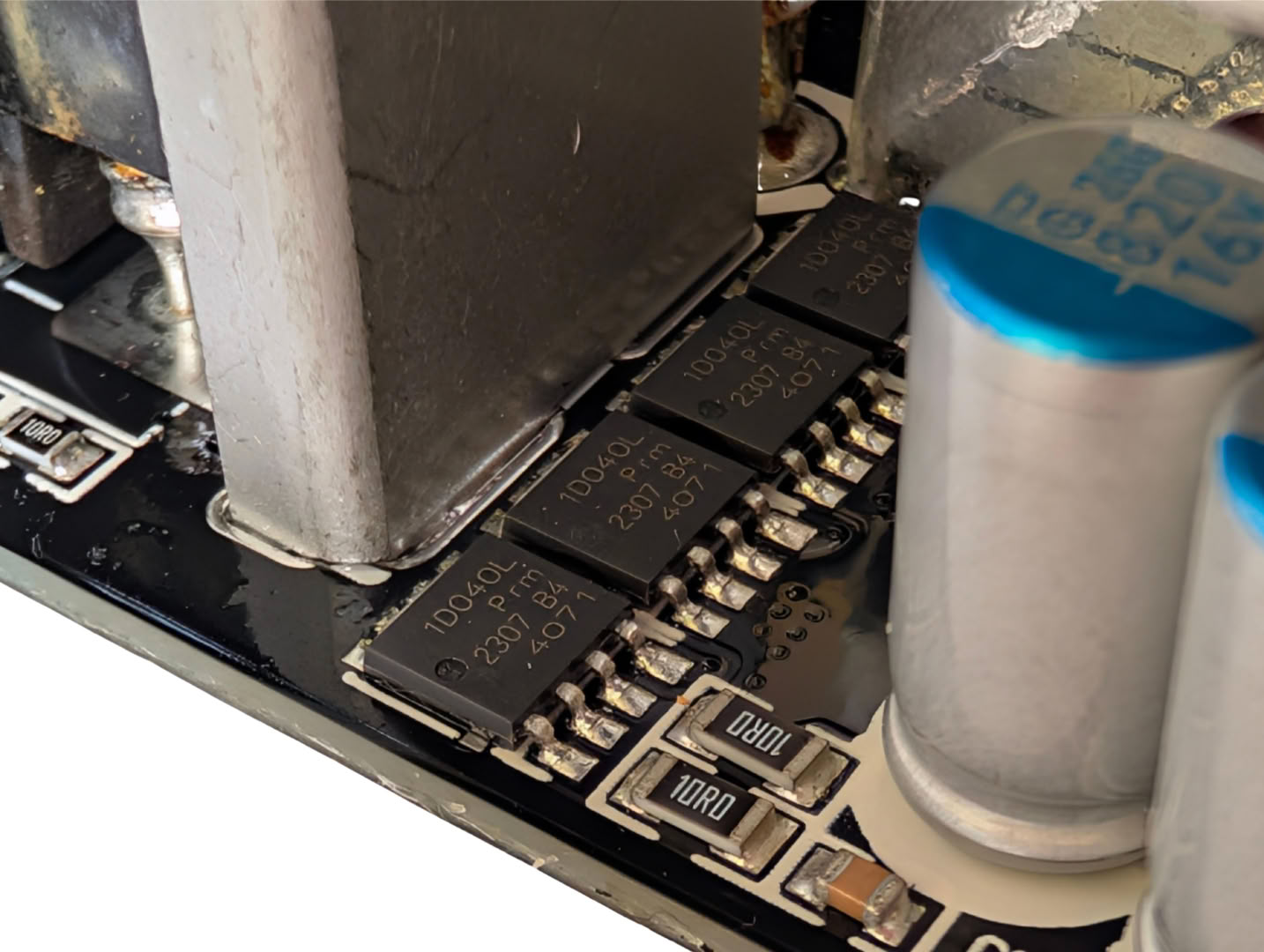
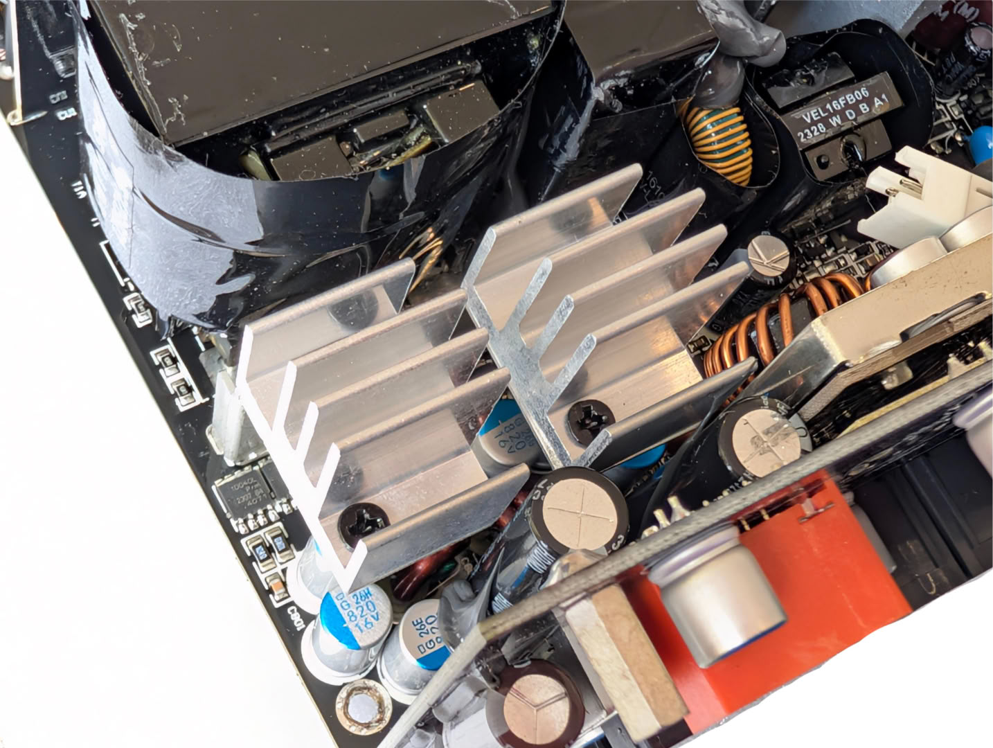
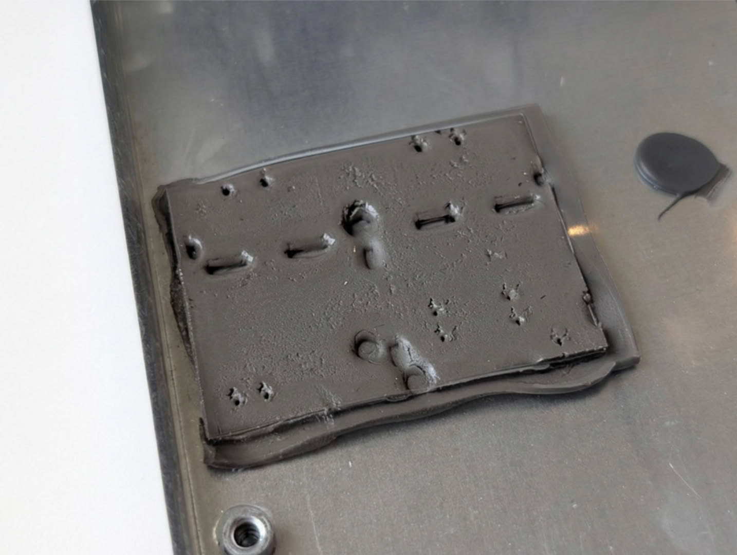
On the top side of the PCB, we find eight Nexperia PSMN1R0-40YLD MOSFETs for the main 12 V rail. These are 40 V, 280 A FETs with an RDS of 0.93 mOhm. They are cooled through thermal mass in the PCB coupled to upright finned heatsinks, and also via thermal pads to the main PSU chassis.
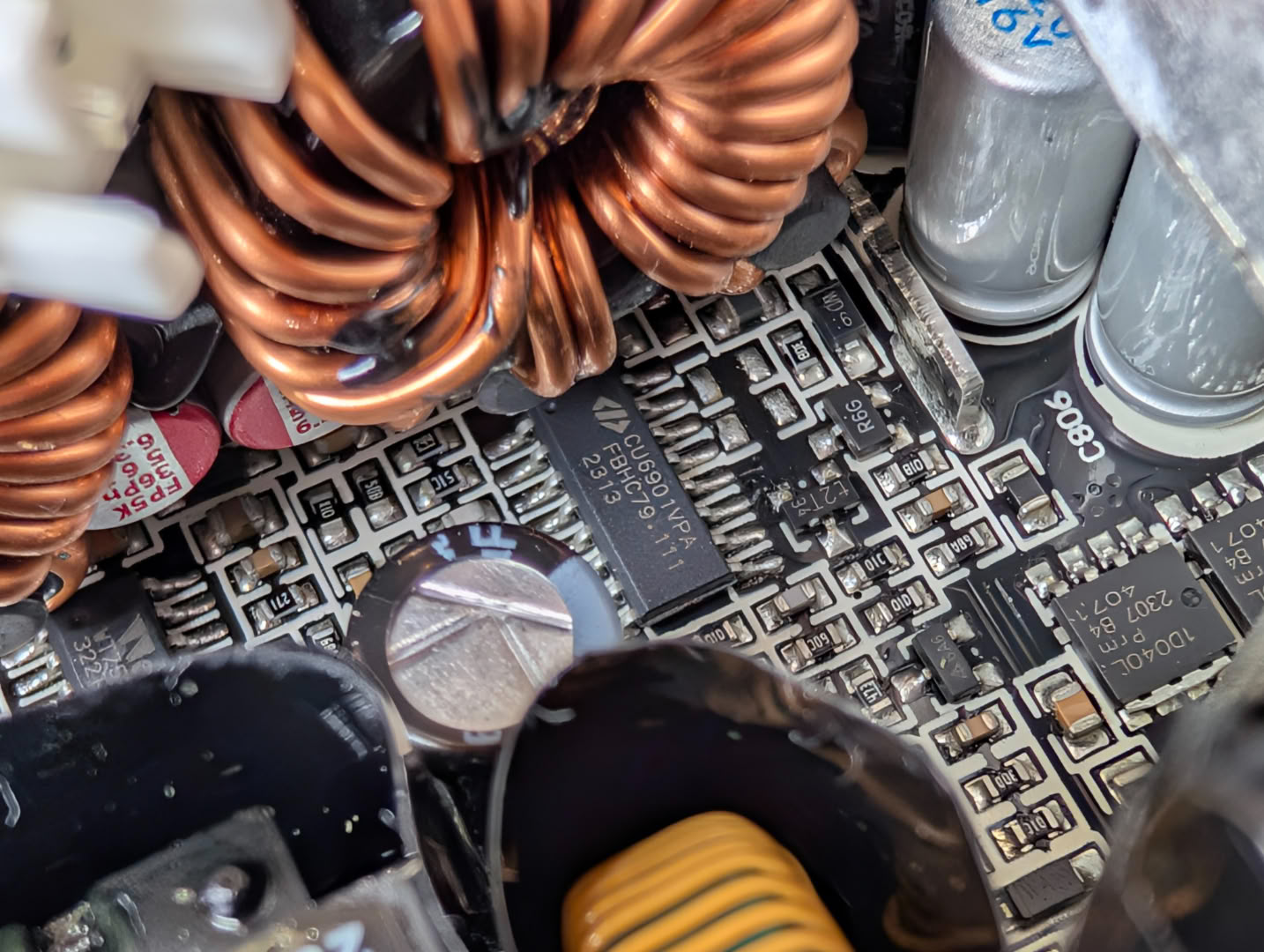
Running the 12 V rail is a CU6901V SLS, SRC/LLC + SR resonant controller, with True NoStandBy ability,
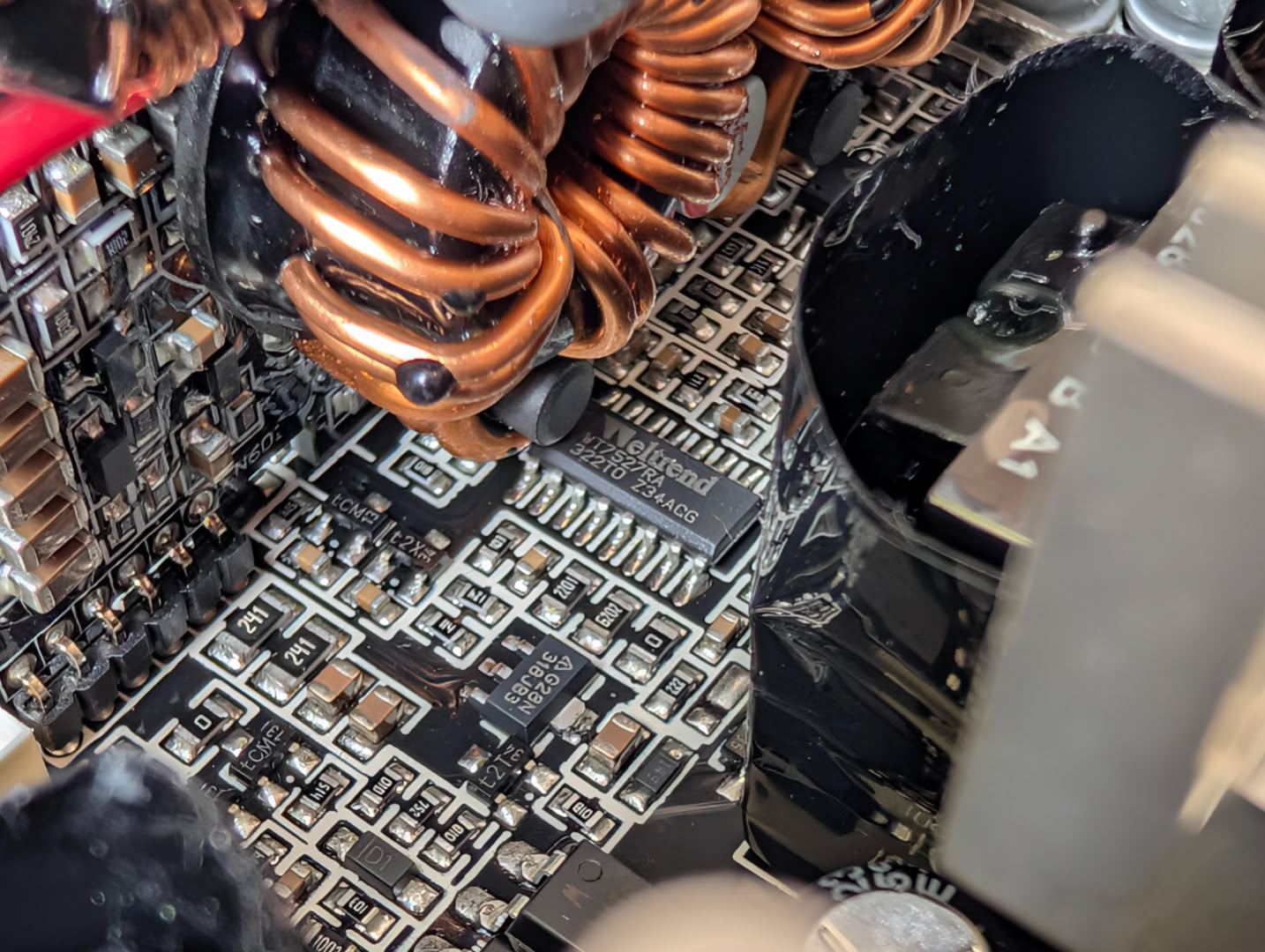
The Weltrend WT7527 supervisor is mounted near to the low voltage auxiliary rails, which manages protection modes OCP, OTP, OVP, UVP, SCP, PG.
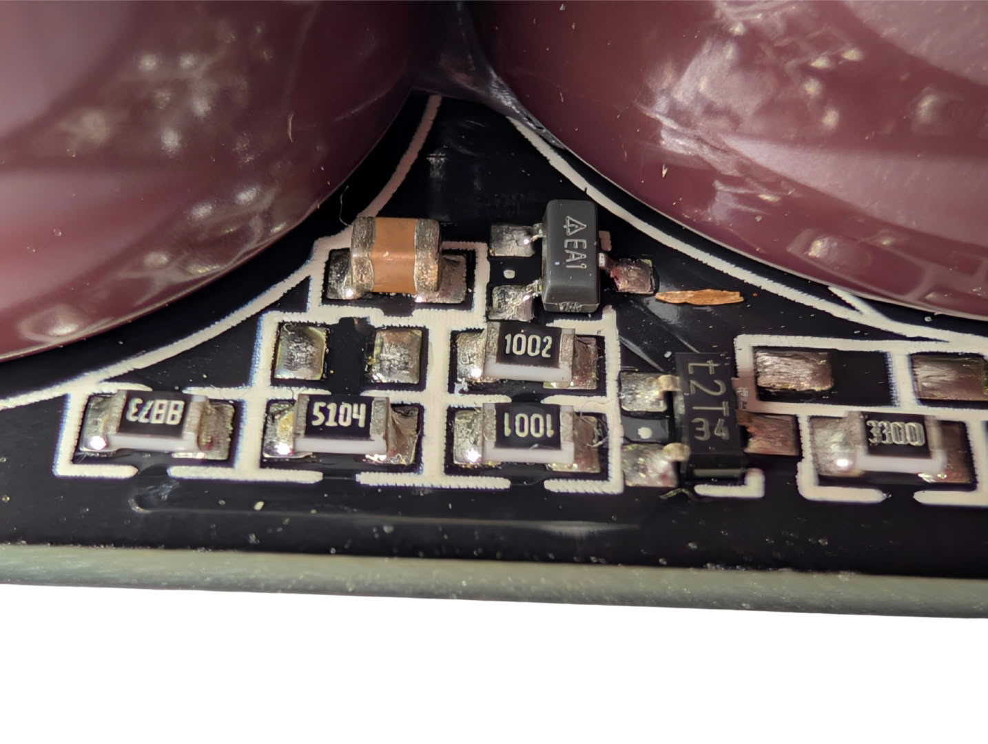
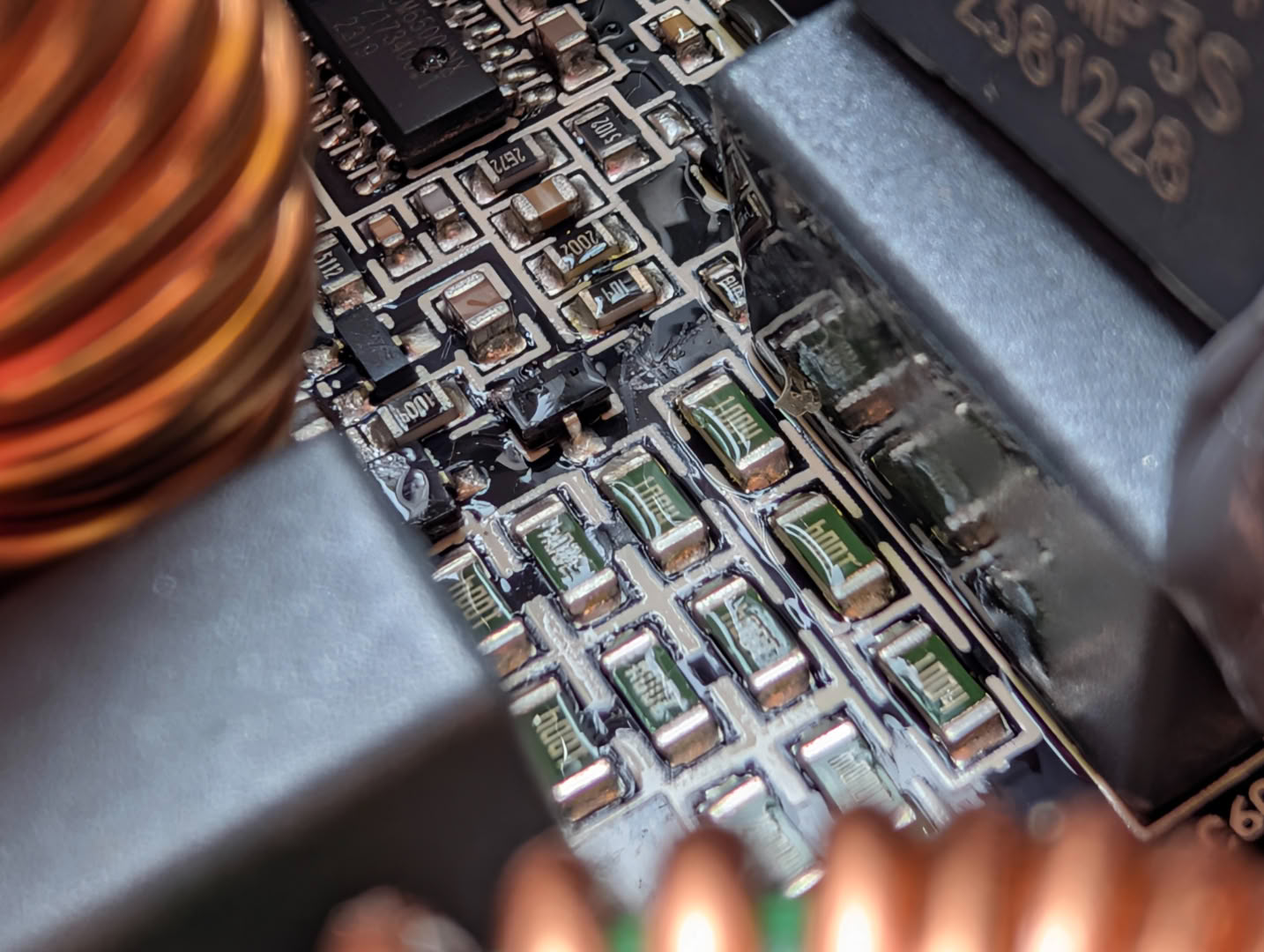
The soldering quality and consistency is fair, and it looks as though some areas of the PCB have been conformal coated. It is unusual to see this localized and not across the whole PCB; it is possible that this area of the circuit is particularly sensitive and any dust or debris, if even slightly conductive, may change its behavior as these are very high value resistors.
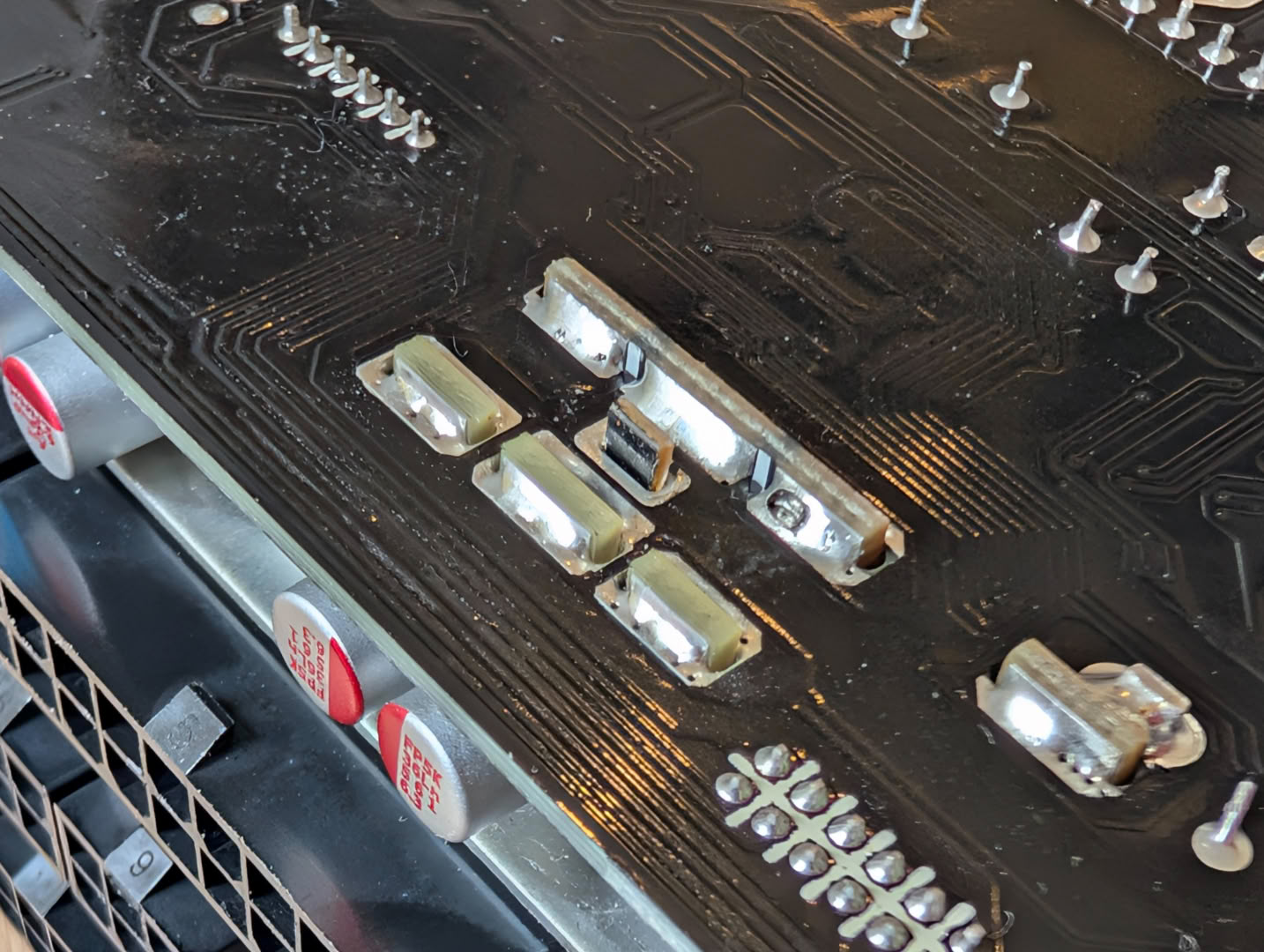
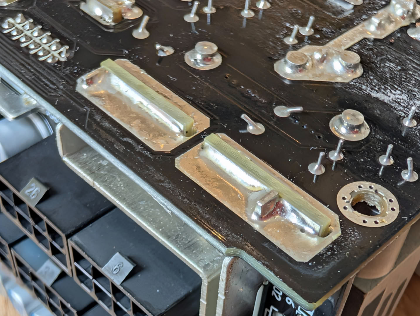
The connector board is soldered to the main PCB with these 90-degree tabs pushed through slots. I am not a fan of this connection style, as the solder is brittle and there is high risk of cracks in the solder from the heavy connector board moving and applying high leverage to these connections. There is also not a great deal of solder used here to strengthen this connection.
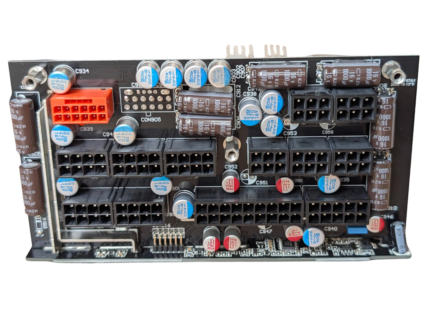
The connector board is rammed with filter caps, although there are a few unused spots for extra caps and a space for a second 12V-2x6 connector, should the brand choose to option this into their model. This suggests that this PCB layout from this OEM may support even higher power ratings than seen here.
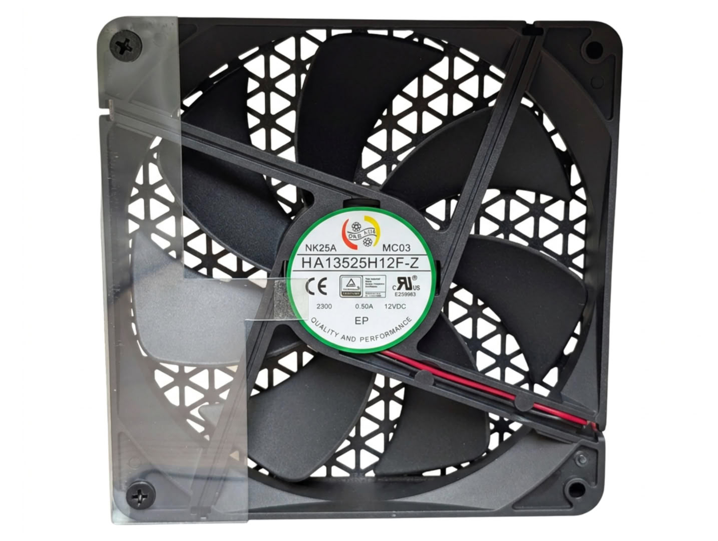
The fan used here is a 135 mm Fluid Dynamic Bearing Fan, model HA13525H12F-Z, rated 0.5 A at 12 V, 2300 rpm.
Nov 19th, 2026 15:58 CST
change timezone
Latest GPU Drivers
New Forum Posts
- Honestly, do you care about GTA VI? (163)
- Windows 11 General Discussion (7736)
- Current Sales, Bundles, Giveaways (10448)
- Last game you purchased? (1409)
- WarpCoreBench scores! (76)
- Got the EOL 32GB TridentZ 6000 CL26 1.4V (12)
- Dell Workstation Owners Club (3516)
- Making a game in Godot engine (4)
- DTS DCH Driver for Realtek HDA [DTS:X APO4 + DTS Interactive] (2815)
- Security Apps (2)
Popular Reviews
- Acemagic Retro X3 Review
- Ugreen NASync DXP4800 GT Review
- Upcoming Hardware Launches 2027 (Updated Nov 2026)
- Pulsar Office Tour & First Look at P1 Dual-Sensor Mouse
- AMD Zen 6 Technical Deep Dive
- Biwin Black Opal NV7400 2 TB Review
- Sapphire Radeon RX 7700 XT Pure Review
- Sapphire Radeon RX 7700 XT Pulse Review
- AMD Ryzen 7 9800X3D Review - The Best Gaming Processor
- Chieftec Iceberg PRO 360 DARK Review
TPU on YouTube
Controversial News Posts
- NVIDIA Co-Founder and CEO Jensen Huang Officially Resigns (488)
- Report: Jensen Huang Eyes NVIDIA Comeback (223)
- Open Letter Asking NVIDIA to Reinstate Jensen Huang Passes 115,000 Signatures (184)
- OpenAI CEO Argues Home PCs Waste the World's Limited DRAM Supply (152)
- NVIDIA Launches Investigation Into Jensen Huang's Relationship With Suspected Chinese Spy (136)
- Intel "Raptor Lake Next" 16-Core and 20-Core CPUs Surface (130)
- Legendary Game Studio BioWare Shuts Down Following EA Layoffs (104)
- Dell CEO Says the Memory Shortage Will Get Worse in 2027 (95)