Given the nature of the kit, there are many different ways to install everything into a case. I will as such only cover the main parts here.
CPU Waterblock
First up is the CPU block on Intel LGA 2011(-3). Start by screwing the M4-threaded mounting screws into the cooler's mounting holes on your motherboard, and apply some TIM to the CPU IHS once you have. I did end up applying more than needed for the demo above, but that always helps identify how good the TIM spread is. Now, maneuver the CPU block into place over these four screws, assuming the Intel mounting bracket is in place already, and place a metal spring over each screw to then tighten these down by using the locking nuts in a cross manner, using diagonal sets of two until you run out of thread. This is a precise mount in that there is no guess work, which also makes it user friendly in that regard.
Installing tubing for each component is fairly simple as well. Begin with removing the collar from the barbed end of the fitting. Now, use this end to install it on the component - the CPU block in this case. The collar goes inward, onto the open end of the tubing which is then forced over the barb. Take your time here and do not apply a lot of pressure inward; you can also dip the tubing in warm water and use pliers to pry the tube open from the inside to make it easier. Once done, simply push the collar down and rotate it to tighten it down, which will hold the tubing in place. There is no need to use any tools here, and finger-tightening the collar will suffice. Do not worry if a couple threads on the fitting's barbed end are still visible as that is normal.
Reversing the process, we see the TIM spread was fairly good, but there was a small uncovered part. There was also some excess TIM that was pushed out, and these have to do more with my TIM application than anything else. The included TIM is electrically non-conductive, so you will not have an issue if you end up doing as I did. For actual testing, I went with two thinner diagonal lines of paste instead, which gave a better, more consistent spread all around the IHS.
Now onto Intel LGA 115x. Begin with the backplate and rubber gasket on the back, making sure the gasket's middle section is removed and the ribbed side of the backplate is facing up with the holes corresponding to the socket latch mechanism's screws, as seen above. The goal is to now have the M3-threaded mounting screws go through a plastic washer, the motherboard PCB, and into the backplate to secure all four in place. I definitely recommend doing this with the motherboard outside of your case unless you have an extra set of hands to help keep everything in place. Note also that the rubber gasket is relatively large and can hit some protruding parts on the back of the motherboard's PCB, as seen above with the mITX motherboard I was using. There is some flexibility due to the rubber material, and as long as the screw holes are uncovered and the screws are in place, it hardly matters that the rubber gasket is hitting something. But double check with your case and motherboard to ensure this is not a deal breaker first. Once done, repeat the same steps as before, but make sure to only apply a grain of TIM in the middle as that will generally suffice for the smaller IHS used here.
Unfortunately, I have no AMD hardware here so please refer to the included manual if you are planning on using this kit with an AMD system.
GPU Waterblock
GPU block installation is even easier, if I do say so myself. I have here a GTX 1080, which has eight VRAM modules, and thus, I only used pre-cut VRAM thermal pads here. Be sure to remove the plastic covers from both sides of the thermal pads before placing them on the VRAM, VRM, and capacitor modules, with the latter merely to prevent electrical shorting, though it could potentially help reduce coil whine if there is any. Note that you will likely have to cut the larger two thermal pad strips to an appropriate length. EKWB recommends applying TIM in a "+" manner on the GPU die as seen in the picture above. Now, place the GPU block over the PCB such that the standoffs in the block match the holes in the PCB and, holding the two together, flip them over to access the back. It will be easier to do so if you have this on a box, such as the GPU block packaging itself, so that the I/O port cover hangs off the side and you have a level base to then screw the two together. Begin with the eight spring-loaded screws around the GPU core, and do not forget the two at the I/O end of the PCB, including the one that requires a nut on the other side.
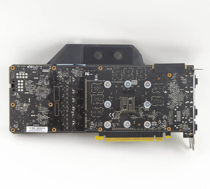
Now, take the backplate and place it such that the cutout is around the SLI fingers. With that done, use the remaining ten screws, putting them through the holes in the backplate and into the remaining ten standoffs in the GPU block, which gives you an actively cooled front waterblock and a passively cooled backplate heatsink. The backplate also prevents any water/coolant leaks due to the radiator/CPU block from hitting the bare PCB in a standard ATX configuration, should there ever be any mishaps. Given how simple everything is, I think even first-time users can do everything on their own just fine.
Reversing the steps, we see good TIM spread and contact with the GPU die and VRAM and VRM modules. If you have the GTX 1080 Ti or any of the two Titan X Pascal cards, the only other thing you will have to do is to cover the other three or four VRAM modules on your card.
 35
35