 14
Formula V Line FV-1200GM Review
Test Methodology »Internals
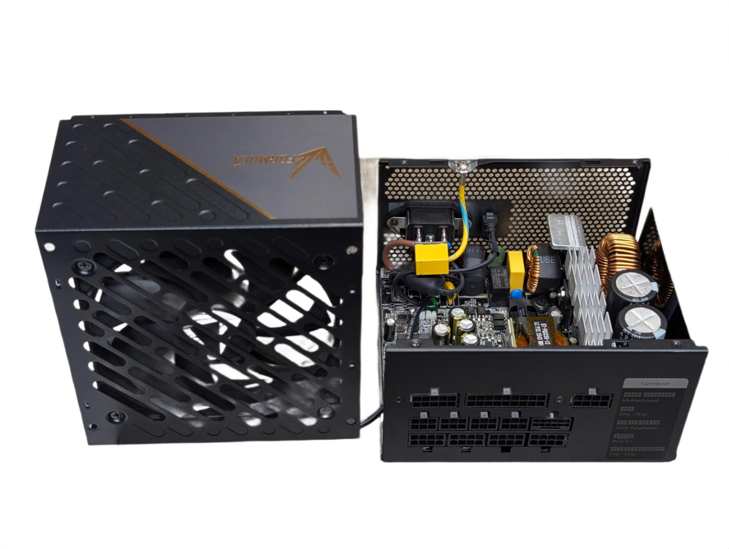
The top panel comes away with four Philips screws.
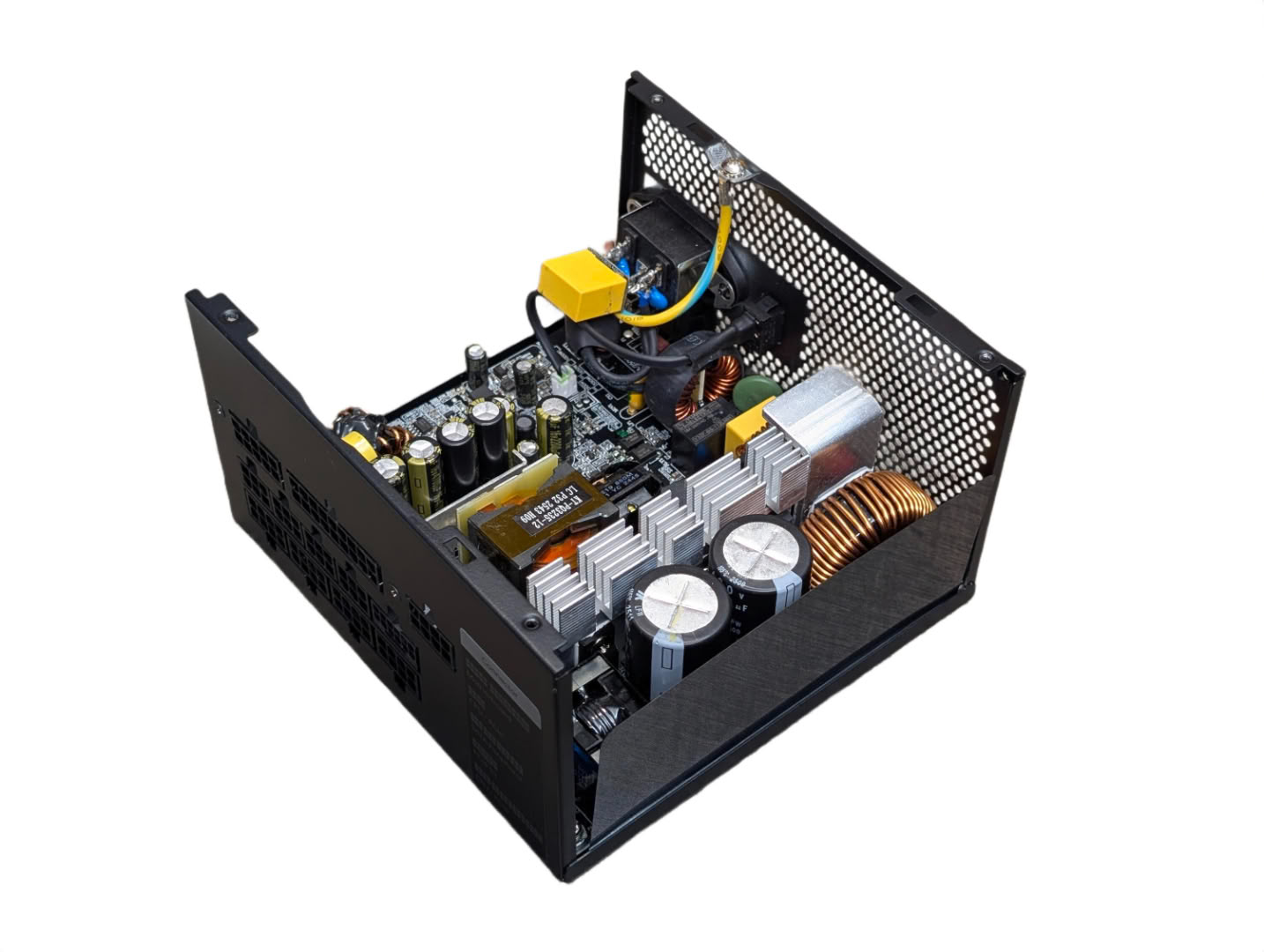
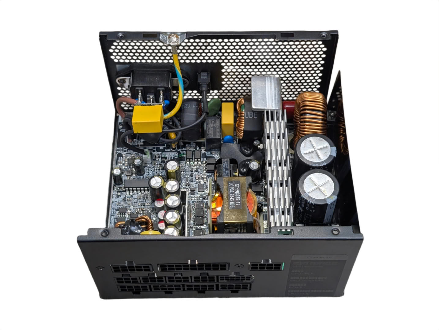
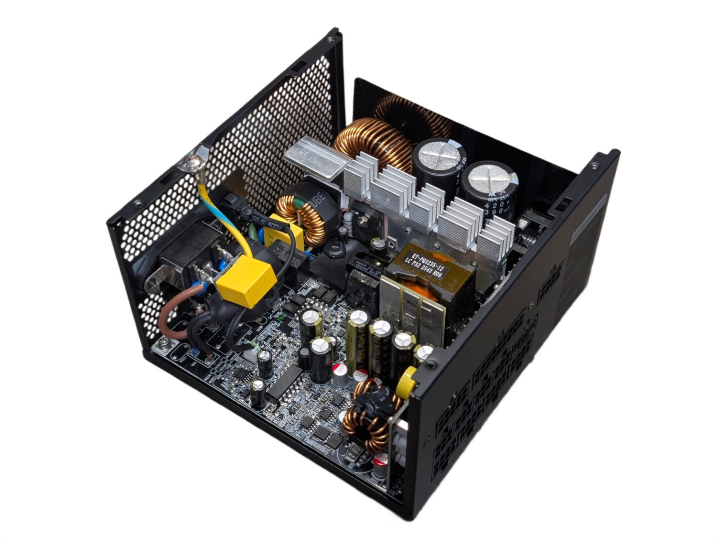
First impressions inside are that it looks quite sparse for a 1200 W rated unit, with a mix of very small SMD and larger DIP package components being used. The topology here is a Half-Bridge LLC Resonant Converter and Synchronous Rectification + DC-DC Converters for the secondary side.
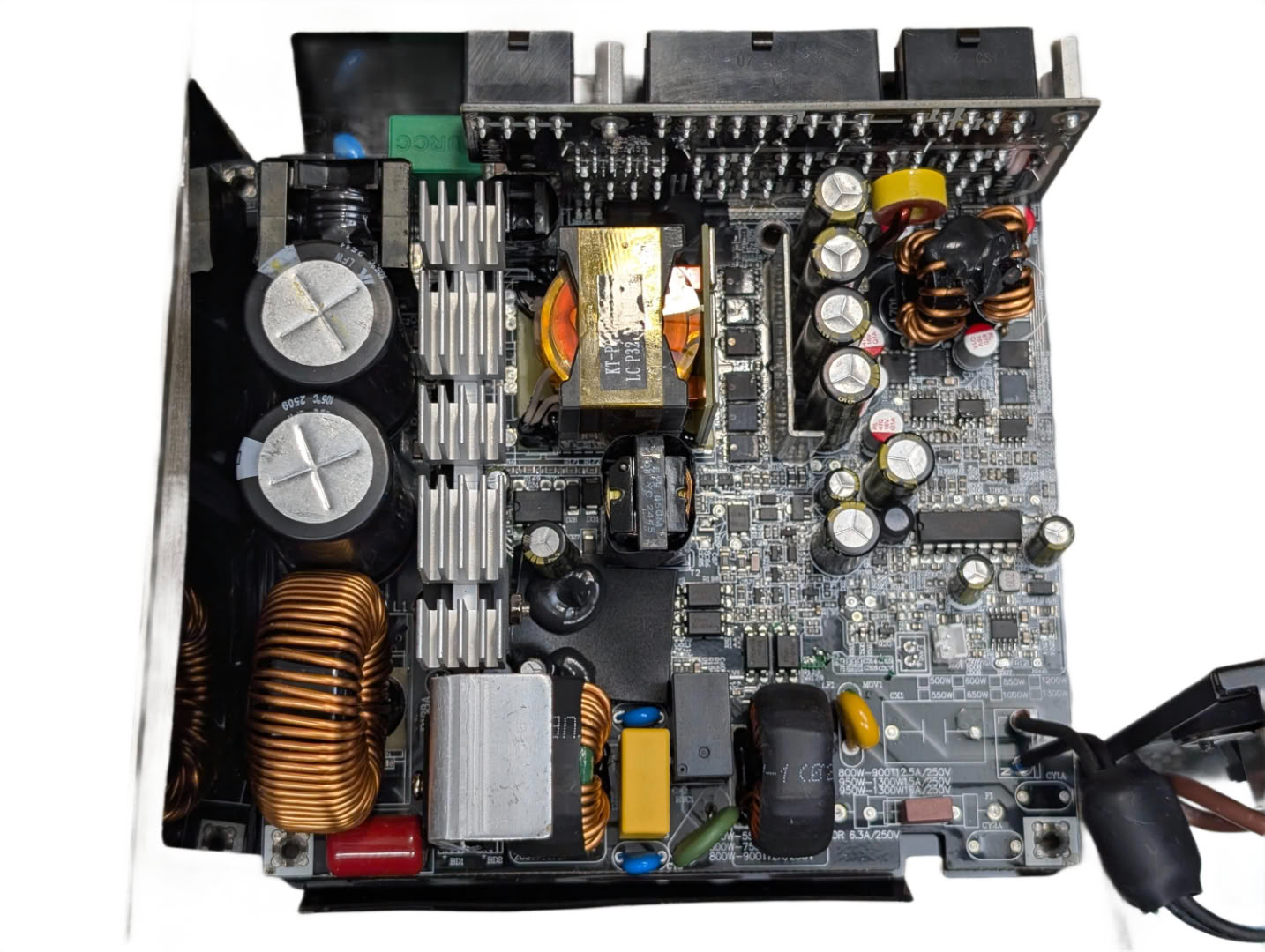
Taking a closer look, we see the layout follows a familiar pattern to other boards, but with the absence of upright daughter boards for things like PWM control, DC-DC converters, and protection circuits. Everything has been mounted to the main PCB.
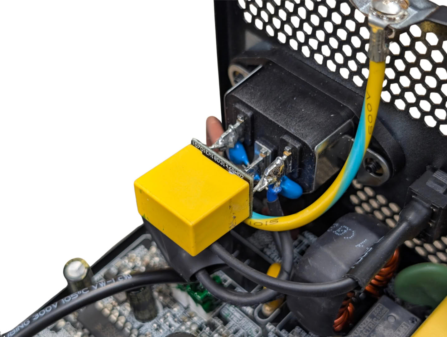
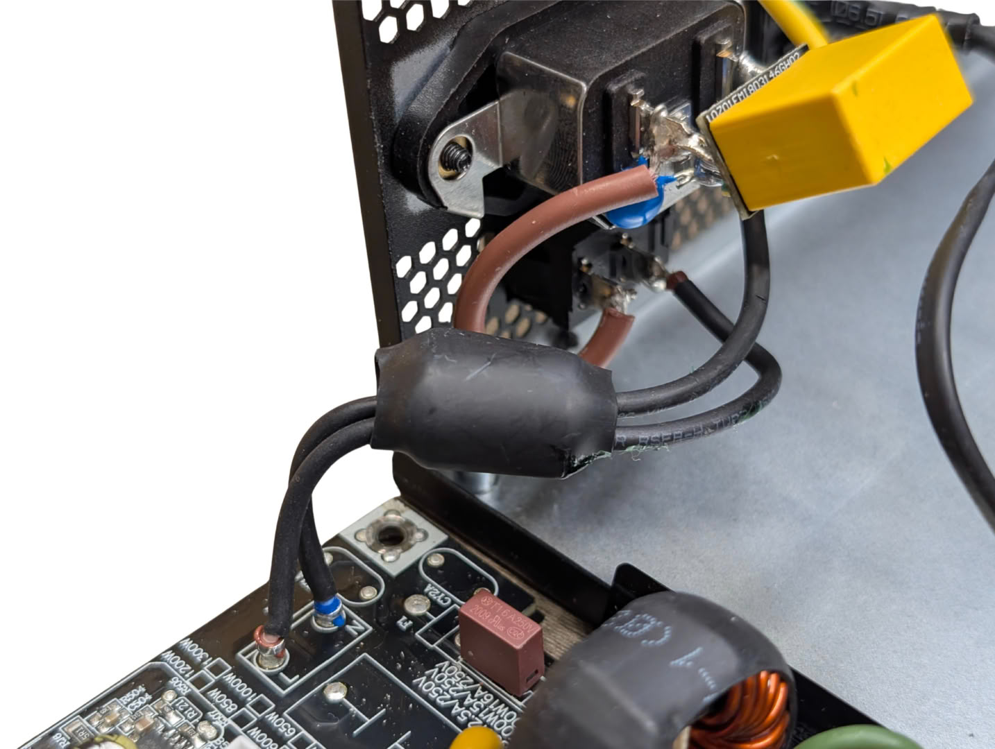
Directly soldered to the power connector, there are a pair of Y caps and an X cap, and a ferrite choke along the power cable to the main PCB.
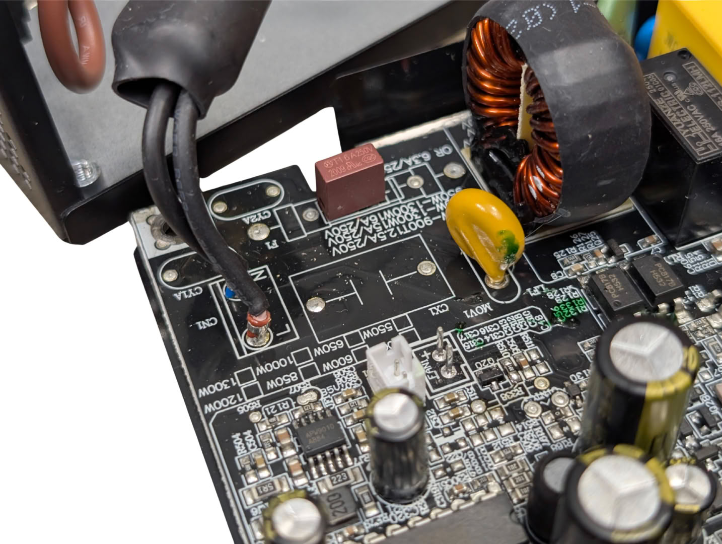
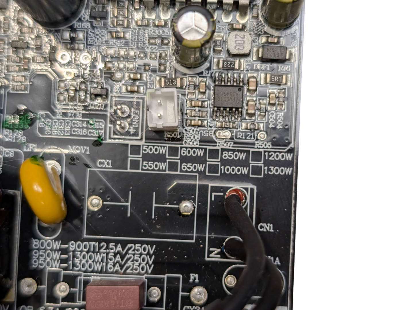
As the mains power enters the PCB, we have empty spots for an additional pair of Y caps and a single X cap. We can also see by the silkscreen print that this board is used across the whole range of models, from 500 W to 1300 W. Given that the 1200 W model appears to be the highest power version offered, I would have thought all the filtering capacitor locations would be populated; perhaps these are reserved for the PM (80 Plus Platinum) variant.
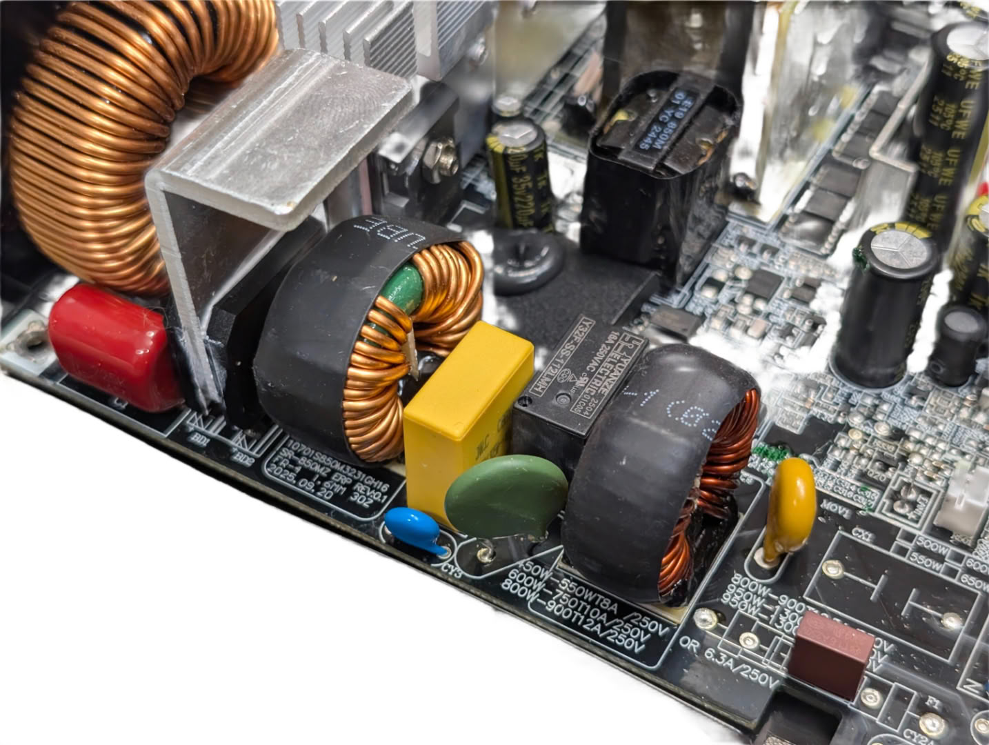
In this unit, we find the inrush suppression relay and thermistor before rectification. The relay will bypass the thermistor once the bulk caps are charged. There is an additional X and Y cap after these components.
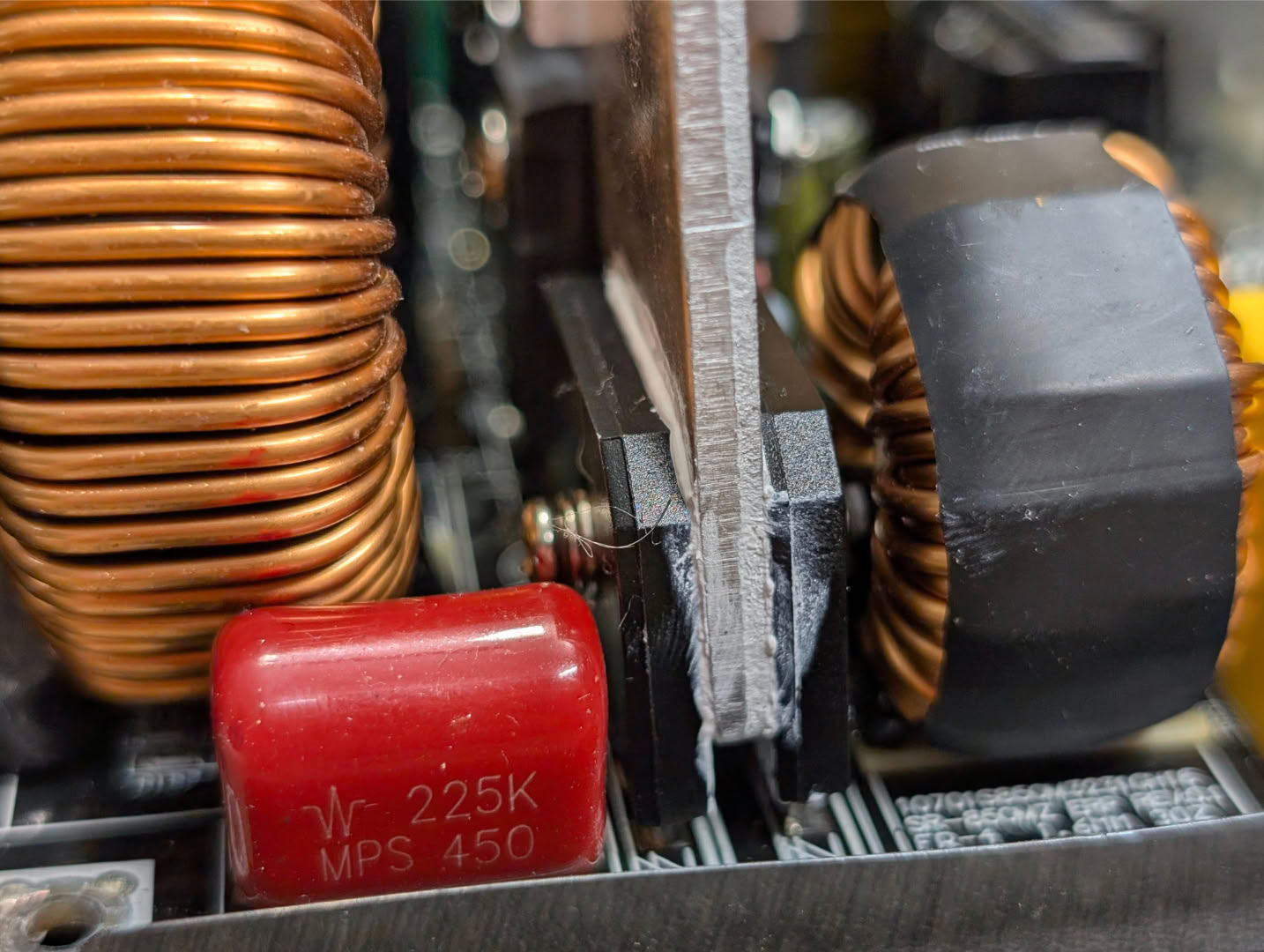
A pair of full bridge rectifiers sandwich a small heatsink.
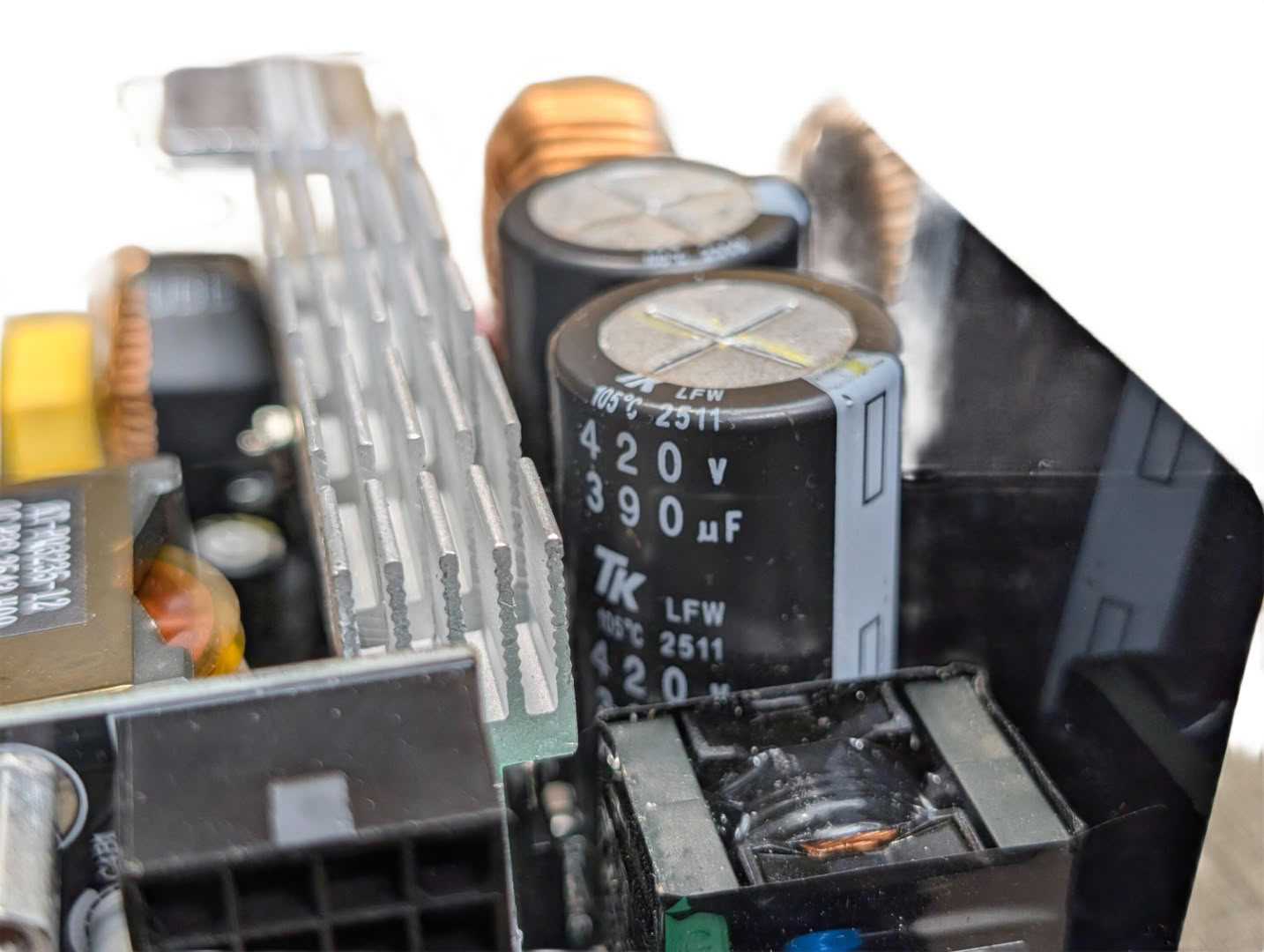
There is 780 uF of bulk capacitance available in a pair of Toshin Kogyo 105°C rated caps. These are decent Japanese models, but certainly more budget oriented than those from the main Japanese manufacturers we often see in other supplies. From a functional and reliability standpoint though, these are perfectly fine.
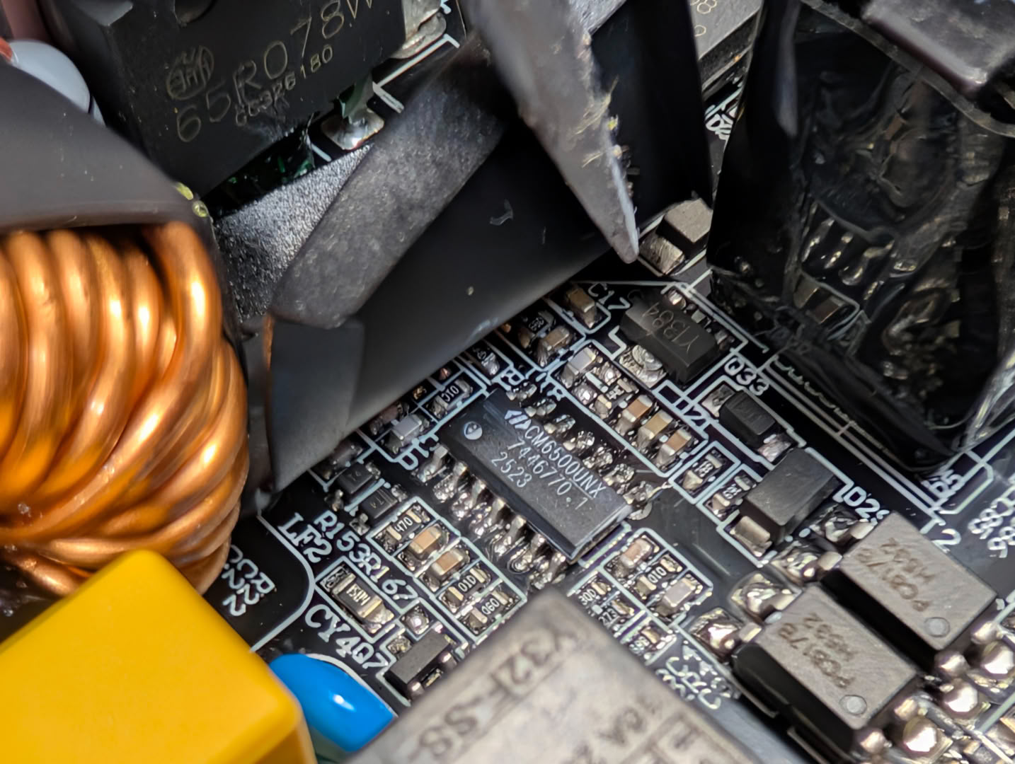
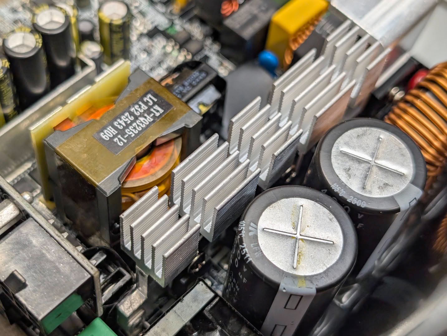
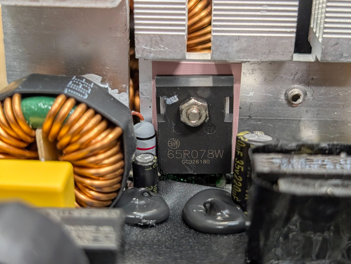
Hiding under a plastic cover, there is a CM6500UNX managing PFC, driving to-220 and to-247ac package components on this main heatsink.
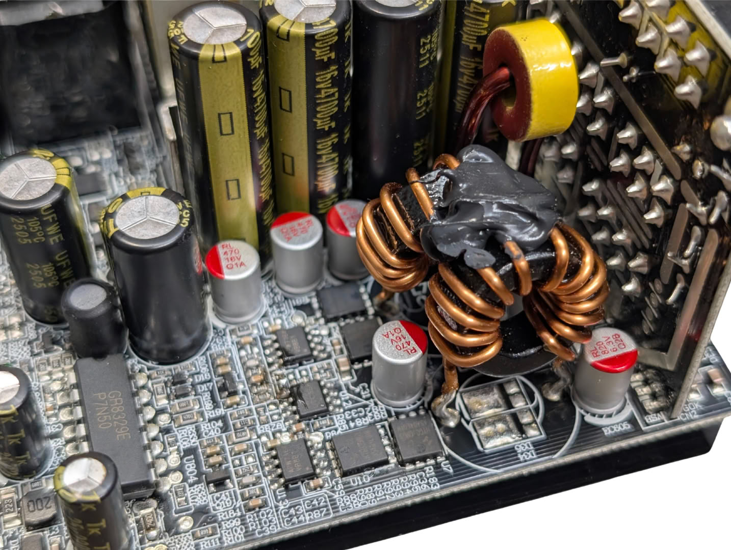
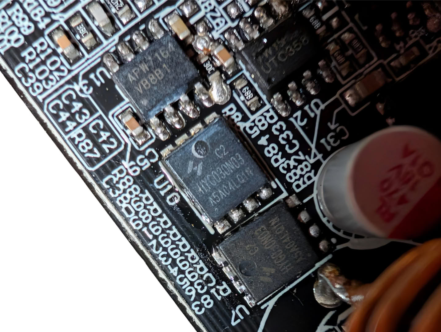
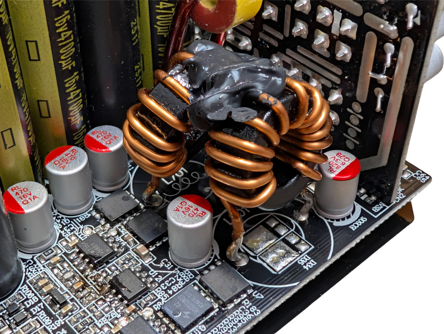
The low voltage rails (5 V, 3.3 V) are created by a DC-DC converter circuit pictured here, consisting of HYG030N03LQ1C2 MOSFETs, capable of 30 V 100 A, with an RDS of 2.4 mΩ. It looks like the original plan was to have the inductors laid flat on the board, but currently they are upright with some adhesive to prevent lead rubbing. Leftover flux on the PCB also suggests some last minute adjustments to the switching circuit have been implemented.
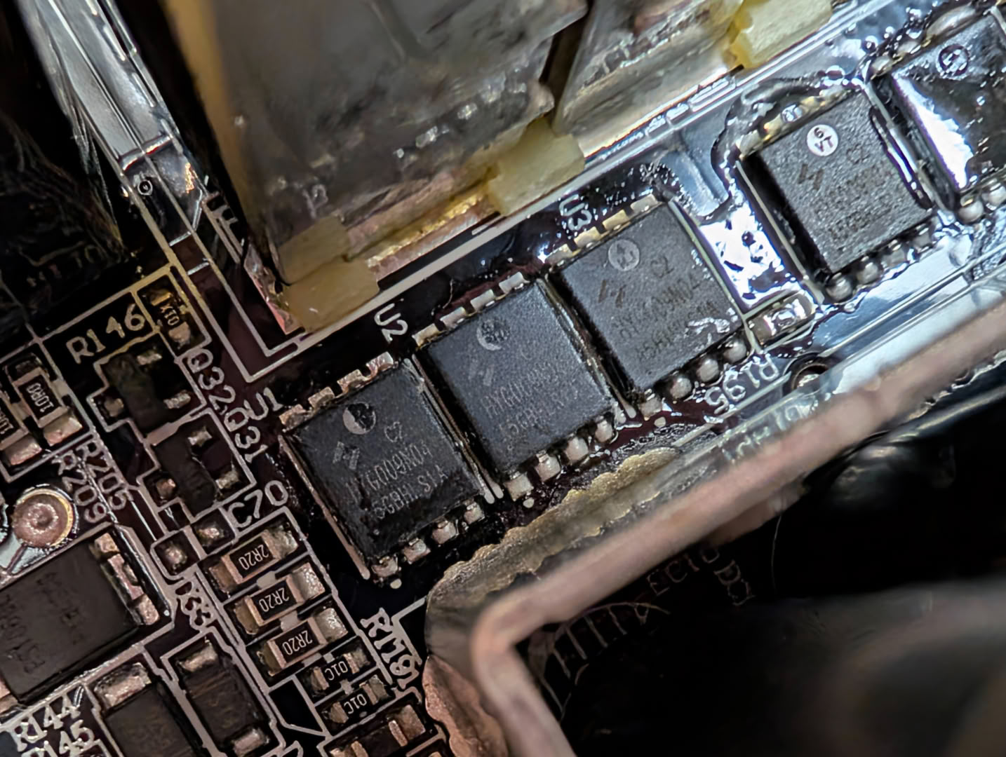
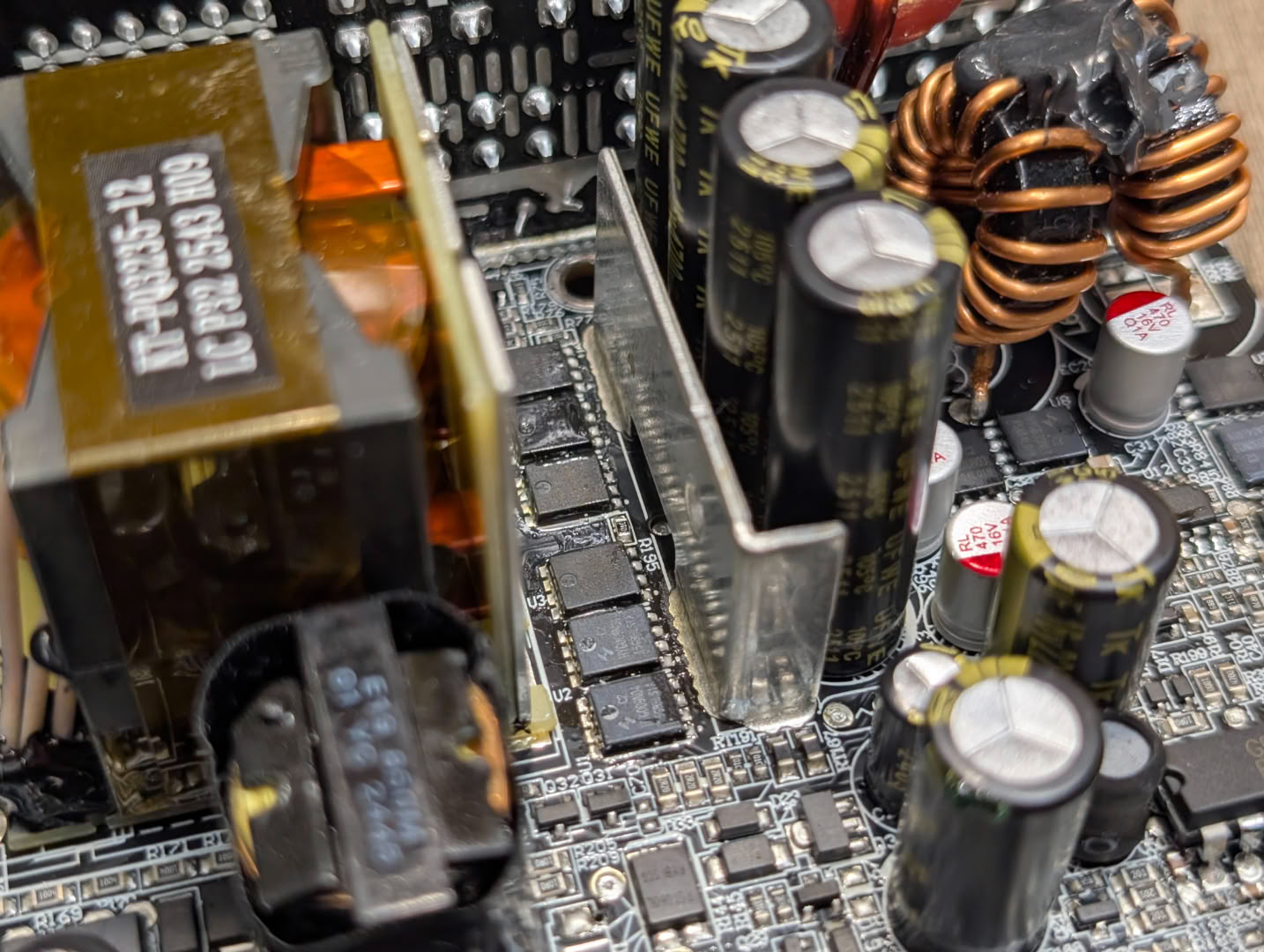
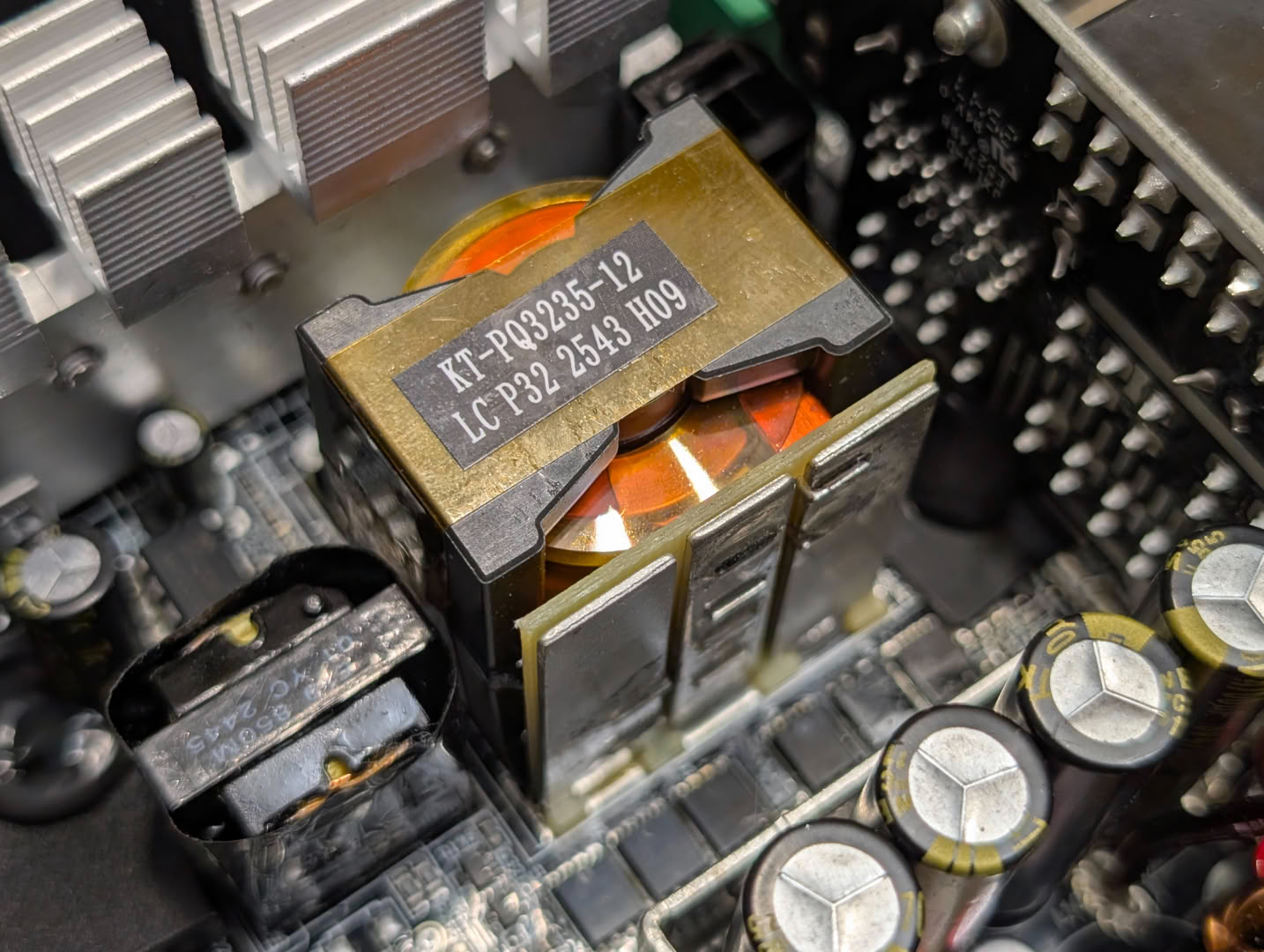
The main 12 V rail is created by a set of six HYG009N04LS1C2 MOSFETs, which are rated for 40 V 200 A, with an extremely low RDS of 0.75 mΩ. There is minimal heatsink given this is a 1200 W rated supply, with only a small metal plate for thermal mass and dissipation in front of the MOSFETs, and the transformer bars will also be able to soak and dissipate some heat. The transformer is an interesting style, using a single thick flat wire for each winding. Usually, multiple smaller isolated wires are preferred due to the skin effect at high frequency switching, but it must have not presented much of a drawback here.
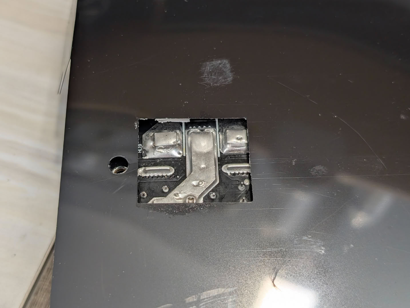
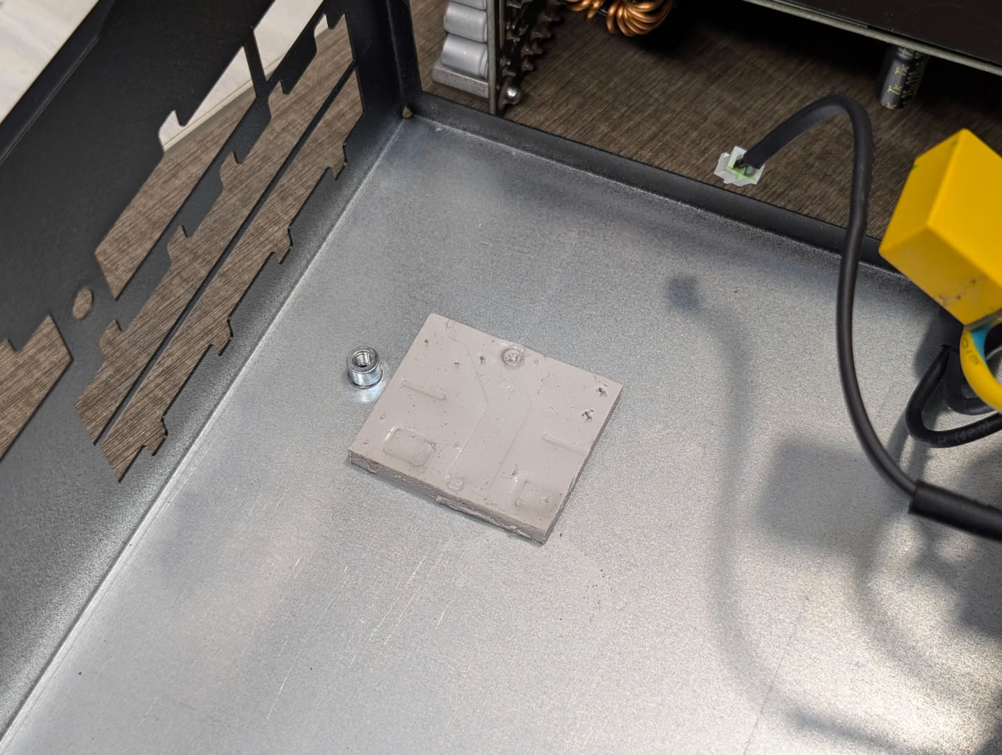
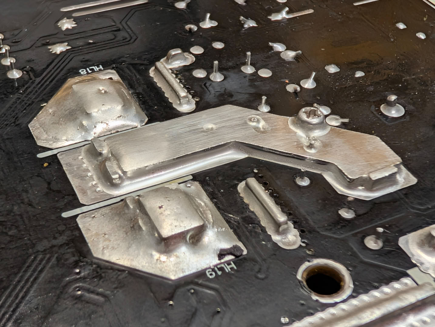
Additional thermal transfer will occur from the underside of the board, through a thermal pad and to the rest of the case. The traces are nice and thick on the underside to aid this.
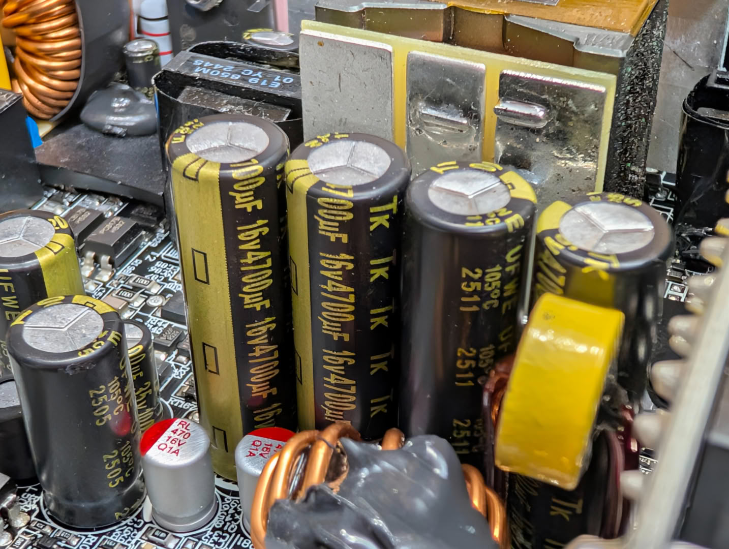
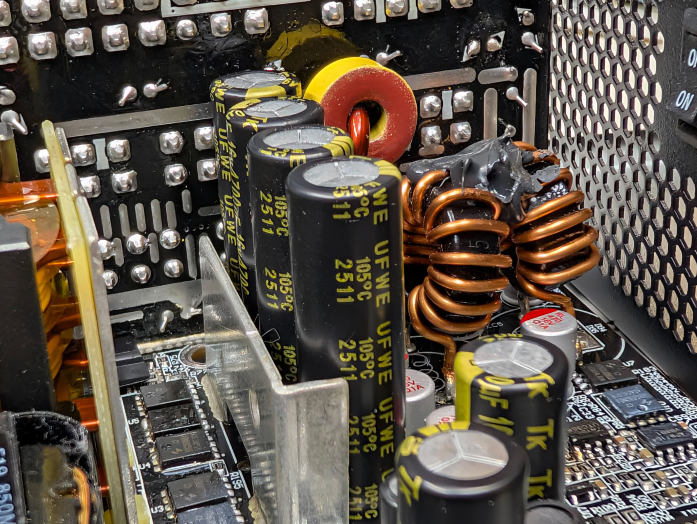
Filtering the output of the 12 V rail, we have a set of four 16 V capacitors, again from Toshin Kogyo, rated for 105°C and totaling 18800 uF.
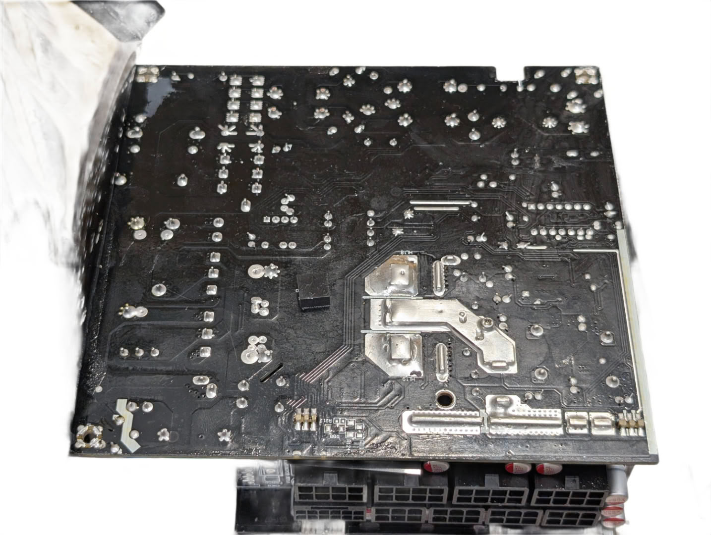
Surprisingly, there aren't really any components on the underside of the board, aside from a few ceramic caps. This really is a minimalistic approach to a 1200 W rated supply compared to others we have seen.
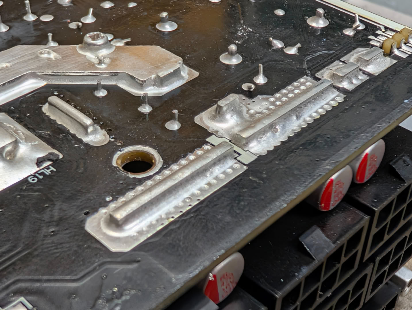
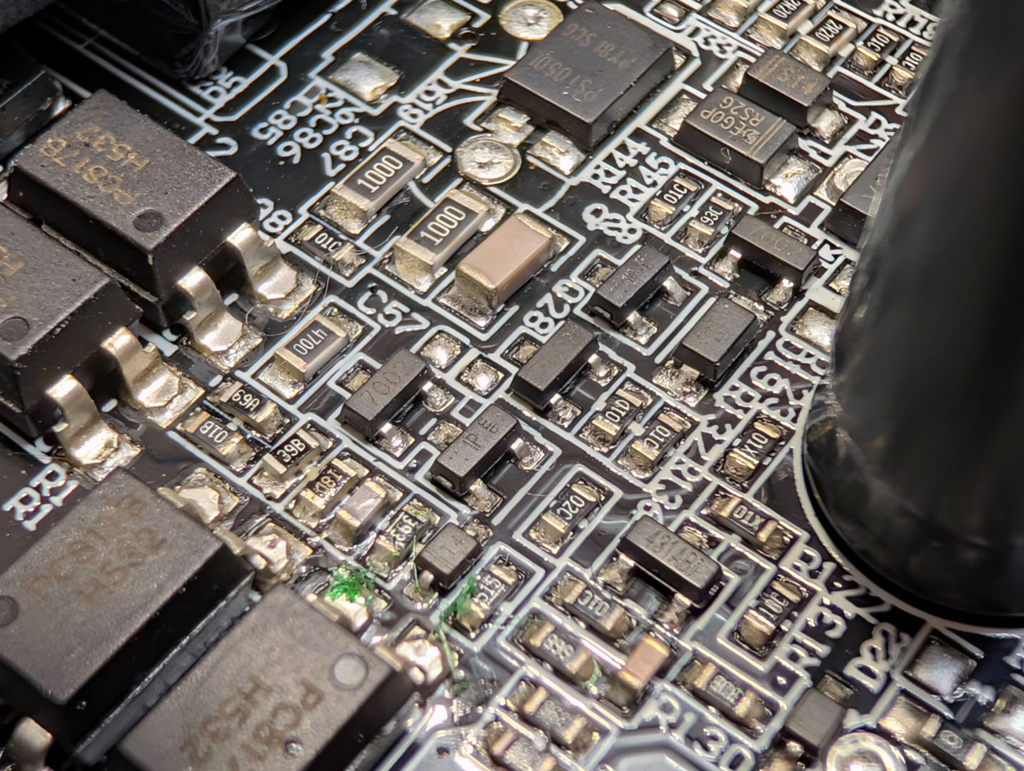
Soldering and assembly quality looks excellent throughout. The connector board is soldered with strong uniform tabs, and the SMD components are neat with an even distribution of solder.
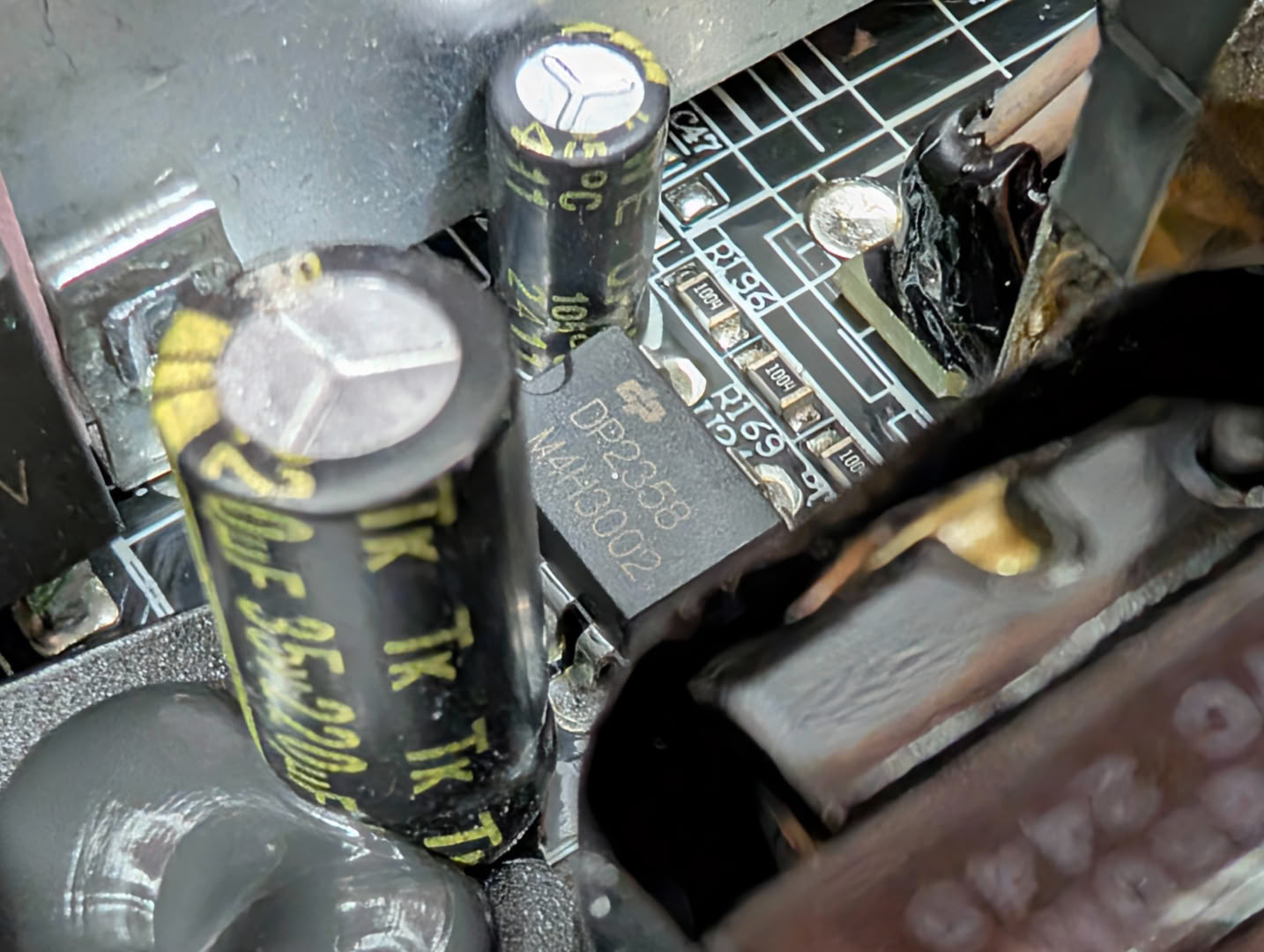
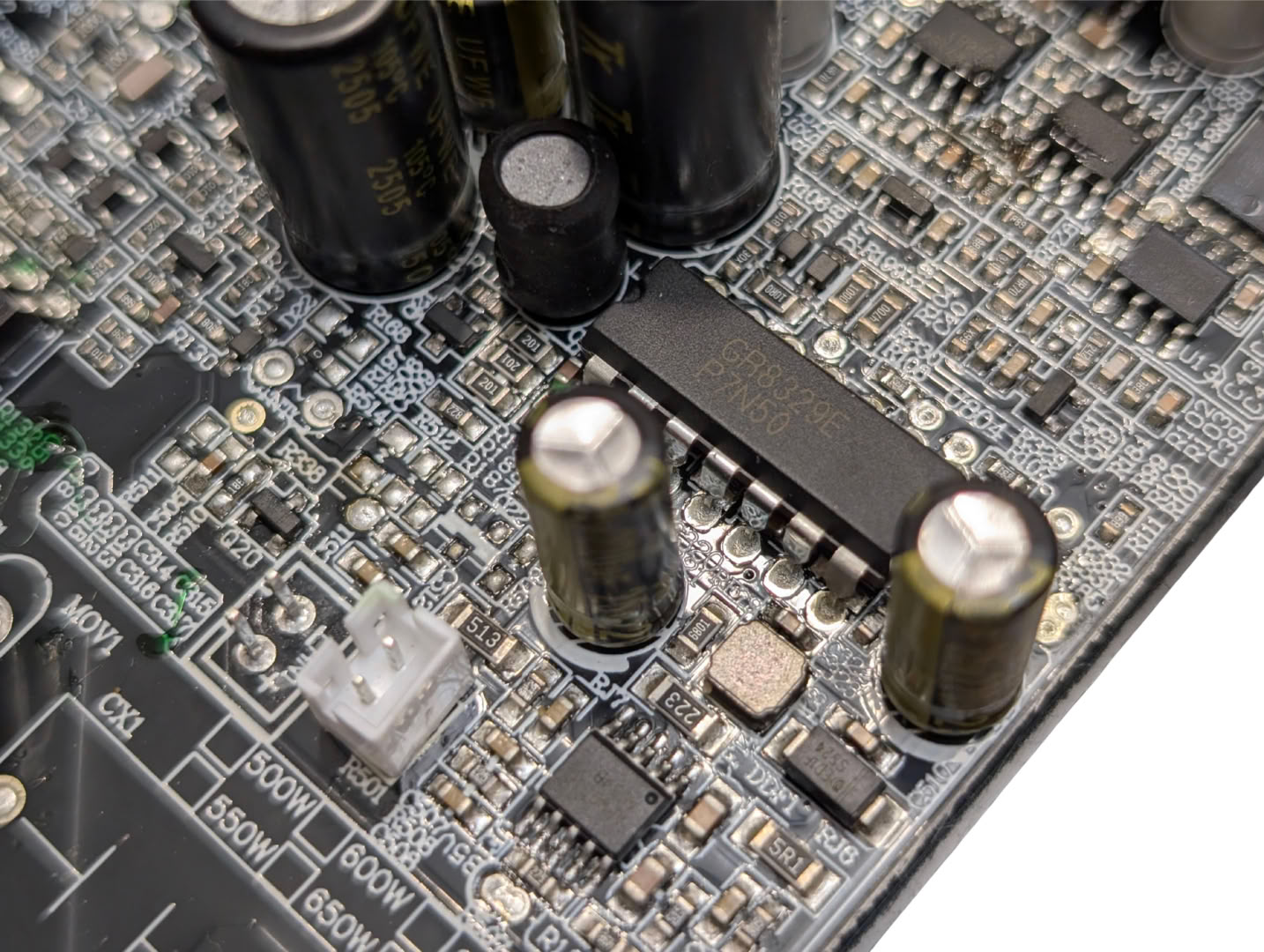
It is unusual to find P-DIP packages in a modern circuit design, but here we find a DP2358 generating the 5 V standby voltage, and more importantly a Grenergy Opto GR8329E 4-Channel Power Supply Supervisor IC, handling overall activation and protection of the various supply voltages.
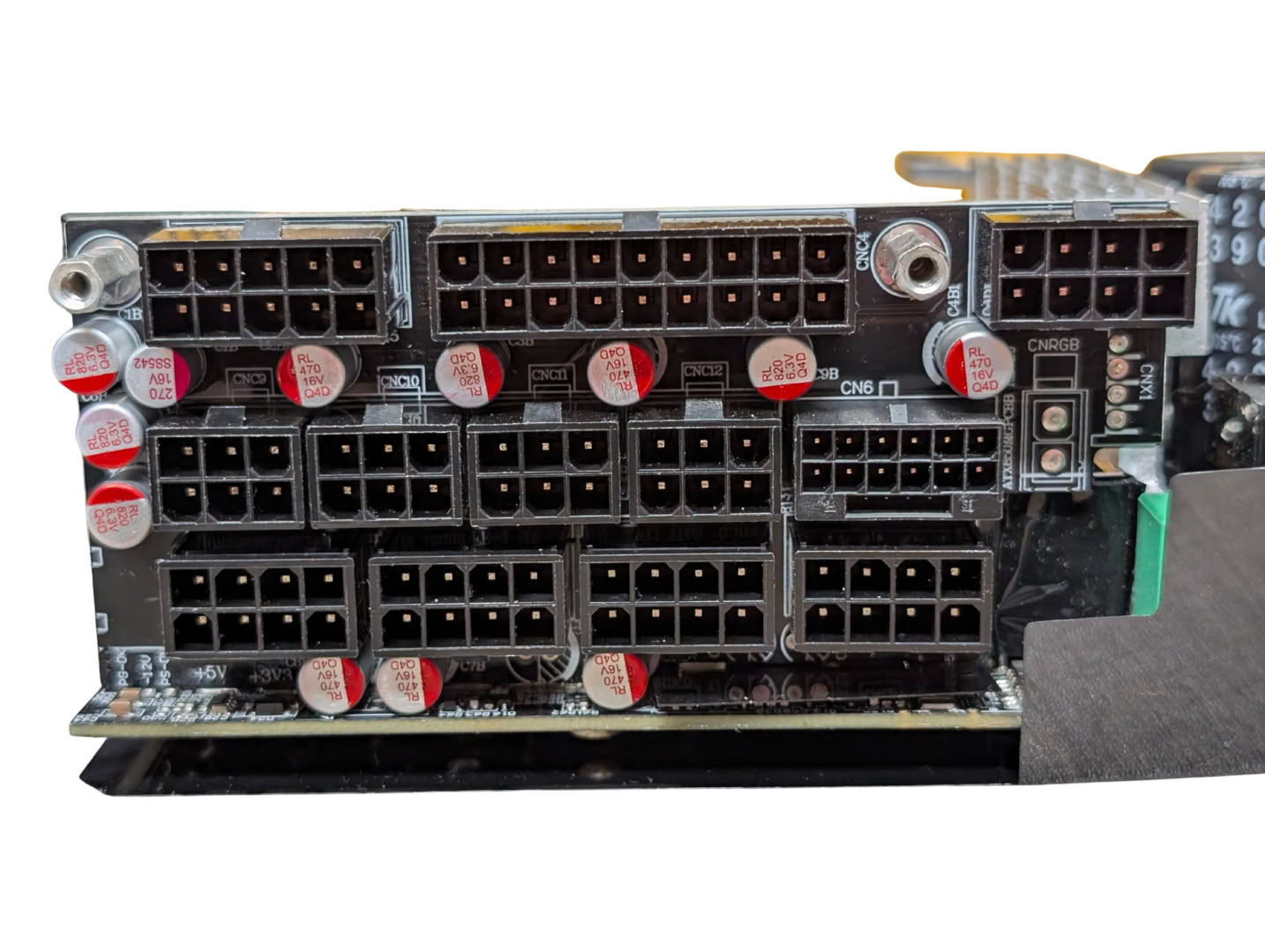
The output connector board houses the connector blocks themselves, and some final filter capacitors alongside. We can also see an unused connector spot for what looks like RGB, which may have been scrapped or planned for a future release.
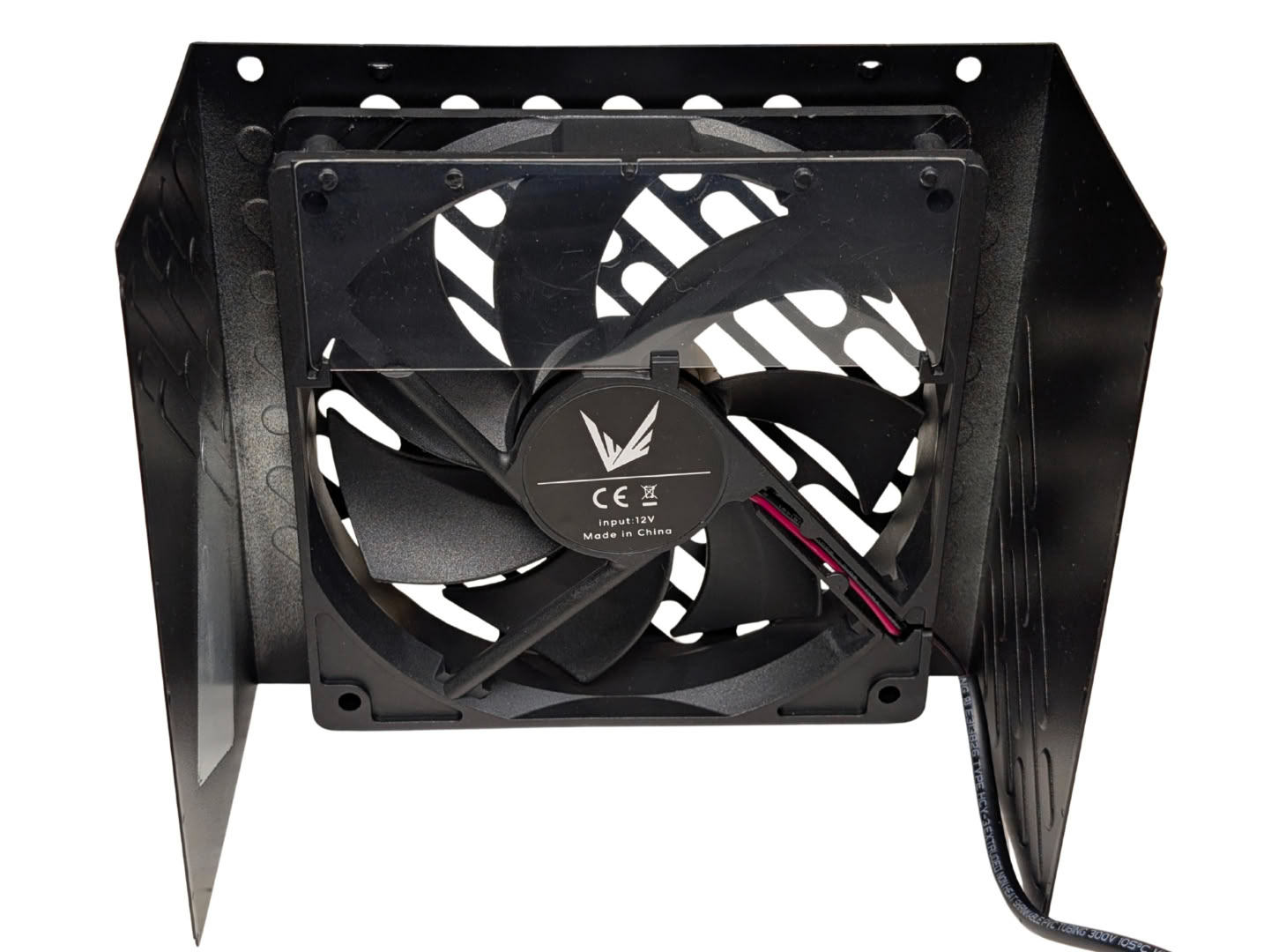
The fan is a generic fluid dynamic bearing 120 mm model with Formula V branding, and no other specs other than a 12 V rating.
Nov 19th, 2026 15:58 CST
change timezone
Latest GPU Drivers
New Forum Posts
- Honestly, do you care about GTA VI? (163)
- Windows 11 General Discussion (7736)
- Current Sales, Bundles, Giveaways (10448)
- Last game you purchased? (1409)
- WarpCoreBench scores! (76)
- Got the EOL 32GB TridentZ 6000 CL26 1.4V (12)
- Dell Workstation Owners Club (3516)
- Making a game in Godot engine (4)
- DTS DCH Driver for Realtek HDA [DTS:X APO4 + DTS Interactive] (2815)
- Security Apps (2)
Popular Reviews
- Acemagic Retro X3 Review
- Ugreen NASync DXP4800 GT Review
- Upcoming Hardware Launches 2027 (Updated Nov 2026)
- Pulsar Office Tour & First Look at P1 Dual-Sensor Mouse
- AMD Zen 6 Technical Deep Dive
- Biwin Black Opal NV7400 2 TB Review
- Sapphire Radeon RX 7700 XT Pure Review
- Sapphire Radeon RX 7700 XT Pulse Review
- AMD Ryzen 7 9800X3D Review - The Best Gaming Processor
- Chieftec Iceberg PRO 360 DARK Review
TPU on YouTube
Controversial News Posts
- NVIDIA Co-Founder and CEO Jensen Huang Officially Resigns (488)
- Report: Jensen Huang Eyes NVIDIA Comeback (223)
- Open Letter Asking NVIDIA to Reinstate Jensen Huang Passes 115,000 Signatures (184)
- OpenAI CEO Argues Home PCs Waste the World's Limited DRAM Supply (152)
- NVIDIA Launches Investigation Into Jensen Huang's Relationship With Suspected Chinese Spy (136)
- Intel "Raptor Lake Next" 16-Core and 20-Core CPUs Surface (130)
- Legendary Game Studio BioWare Shuts Down Following EA Layoffs (104)
- Dell CEO Says the Memory Shortage Will Get Worse in 2027 (95)