 4
4
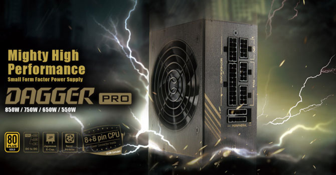
FSP Dagger Pro 850W Review - Tiny Power Plant
(4 Comments) »Introduction
We would like to thank FSP for supplying the review sample.
FSP's Dagger Pro line consists of four SFX form factor models with capacities ranging from 550 to 850 W. In this review, I will take a detailed look at the strongest member of the line, which is among the strongest SFX PSUs available on the market today. Since this is a powerful, compact PSU and some users would like to use it with a normal ATX chassis, FSP was kind enough to throw an SFX to ATX adapter into the bundle. For most SFX PSUs, such an adapter doesn't make much sense since they have short cables, which leads to compatibility issues. With the 850 W Dagger Pro, the cables that matter, ATX and EPS, are long, so you won't have a problem unless installing it into a cave-sized chassis. On the other hand, long cables can be an issue for cable management inside a small Mini-ITX chassis.
The other specifications of the Dagger Pro unit include a single +12 V rail, the semi-passive operation, Japanese electrolytic capacitors for increased reliability, and a double ball-bearing fan. Most manufacturers prefer fluid dynamic bearing fans because they produce less output noise. Still, ball-bearing fans are highly tolerant to high operating temperatures, making them more suitable for stressful conditions. In addition to that, with the proper fan-speed profile, noise output can be kept low at normal operating temperatures even with a double ball-bearing fan.
Specifications
| Features & Specifications | |
|---|---|
| Max. DC Output | 850 Watt |
| PFC | Active PFC |
| Efficiency (115 V) | 80 PLUS Gold, Cybenetics Platinum |
| Efficiency (230 V) | Cybenetics Silver |
| Noise | Cybenetics Standard+ (35–40 dBA) |
| Modular | Yes (fully) |
| Intel C6/C7 Power State Support | Yes |
| Operating Temperature | 0–50 °C |
| Protections | Over Voltage Protection Under Voltage Protection Over Power Protection Over Temperature Protection Over Current Protection Short Circuit Protection |
| Cooling | 92mm double ball bearing fan (PLA09215B12H) |
| Semi-Passive Operation | Yes |
| Dimensions (W x H x D) | 125 x 65 x 100 mm |
| Weight | 0.95 kg (2.09 lb) |
| Compliance | SFX12V V3.3, EPS 2.92 |
| Warranty | 10 years |
| Price at Time of Review (excl. VAT) | $209.99 |
| Power Specifications | |||||||
|---|---|---|---|---|---|---|---|
| Rail | 3.3 V | 5 V | 12 V | 5 VSB | -12 V | ||
| Max. Power | 20 A | 20 A | 70.83 A | 2.5 A | 0.3 A | ||
| 120 W | 850 W | 12.5 W | 3.6 W | ||||
| Total Max. Power | 850 W | ||||||
The Dagger Pro 850 W is only Cybenetics Silver certified with 230 V input because of the increased standby power (>0.2 W). With 115 V input, it is Cybenetics Platinum certified.
Photos

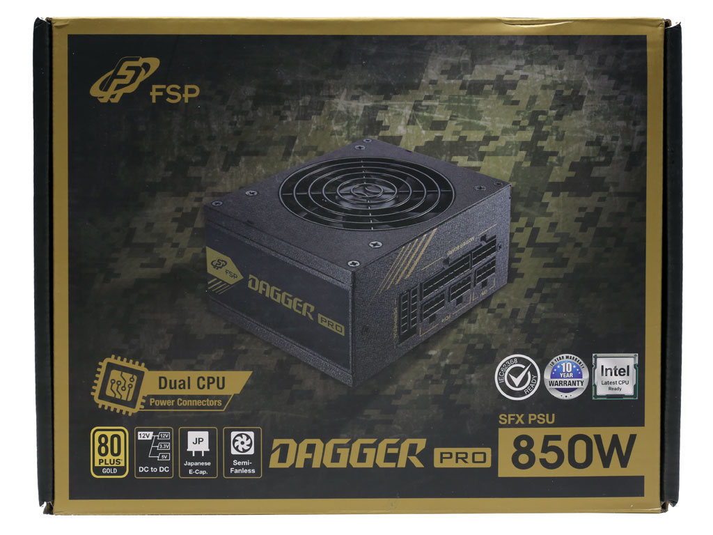

At the face of the box is a photo of the PSU, along with the model name, capacity description, and several badges depicting the unit's efficiency, Japanese capacitors, DC-DC converters for the minor rails, semi-passive operation, and ten-year warranty. FSP also has an icon for the dual EPS (CPU) connectors of this PSU. On the back, the most important features of this product are covered.


Protection inside the box is good since a foam spacer surrounds the PSU. The bundle includes the user manual, fixing bolts, and the SFX to ATX adapter bracket.

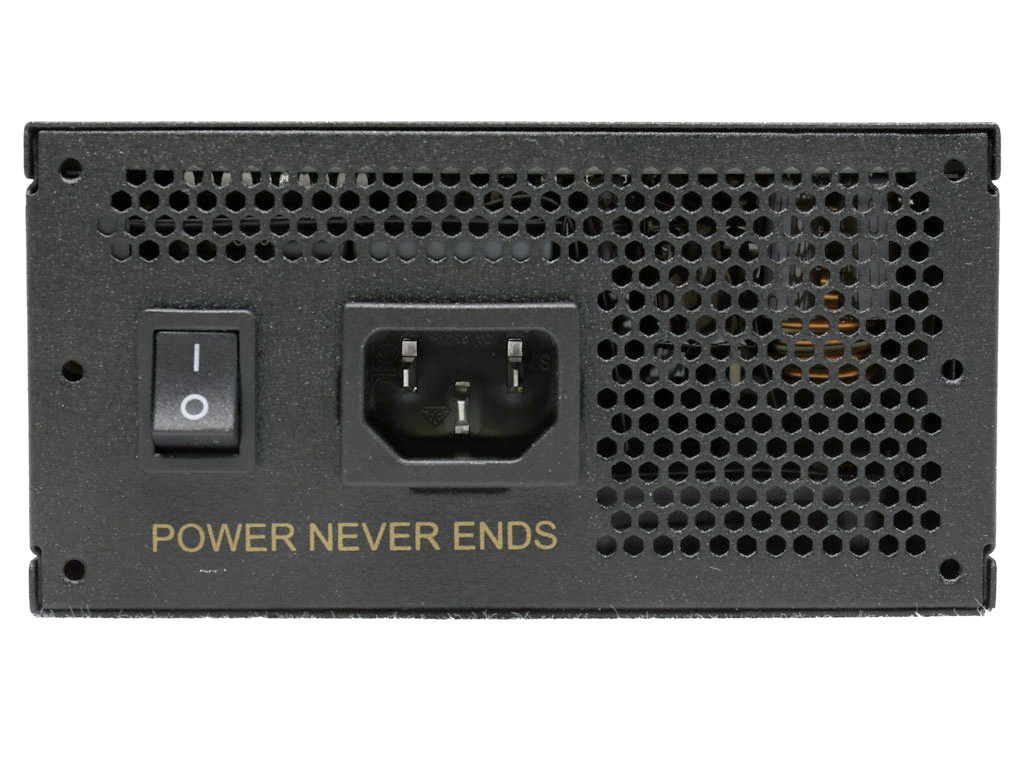
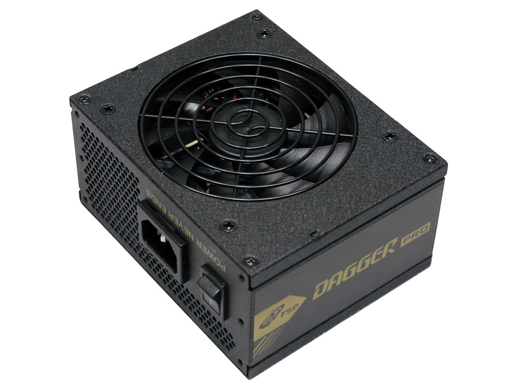
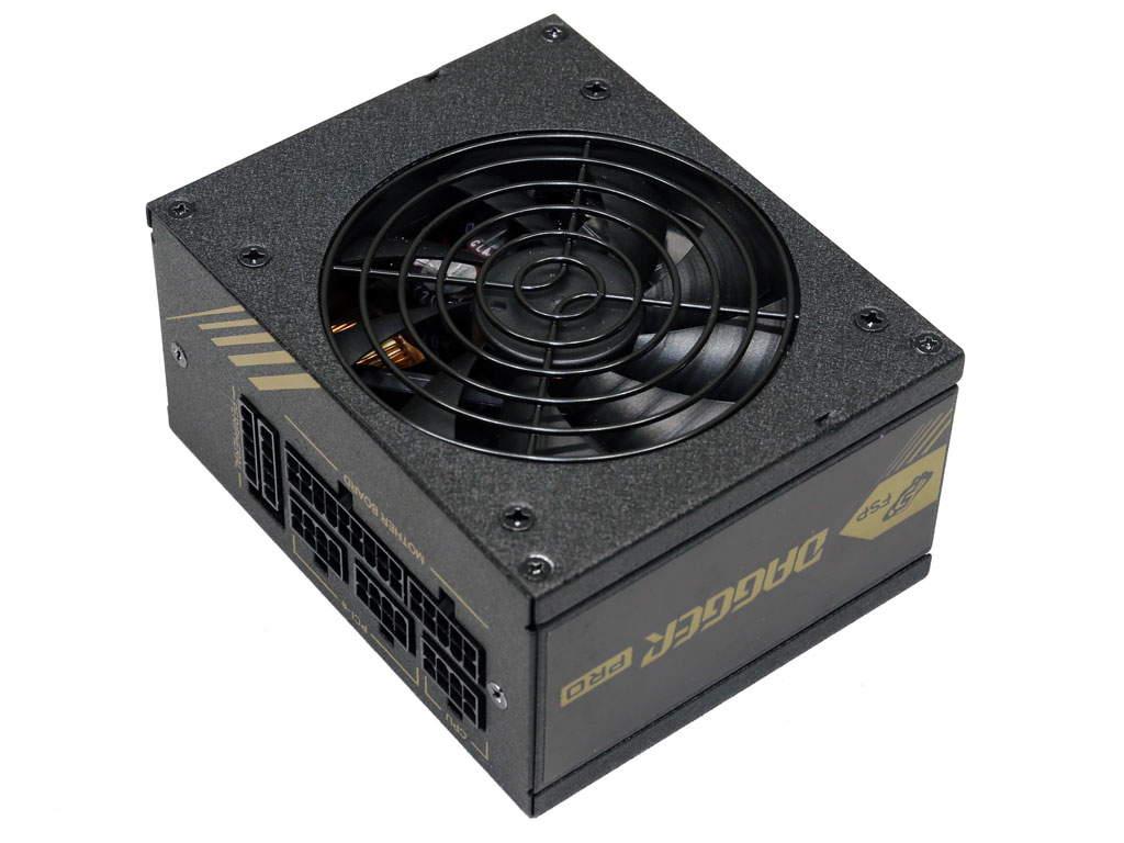
The cooling fan is not centered. This tends to be a trend with small form factor PSUs. At the front, we have the on/off switch and AC inlet. There is no switch to toggle off the unit's semi-passive operation, which is a shame.

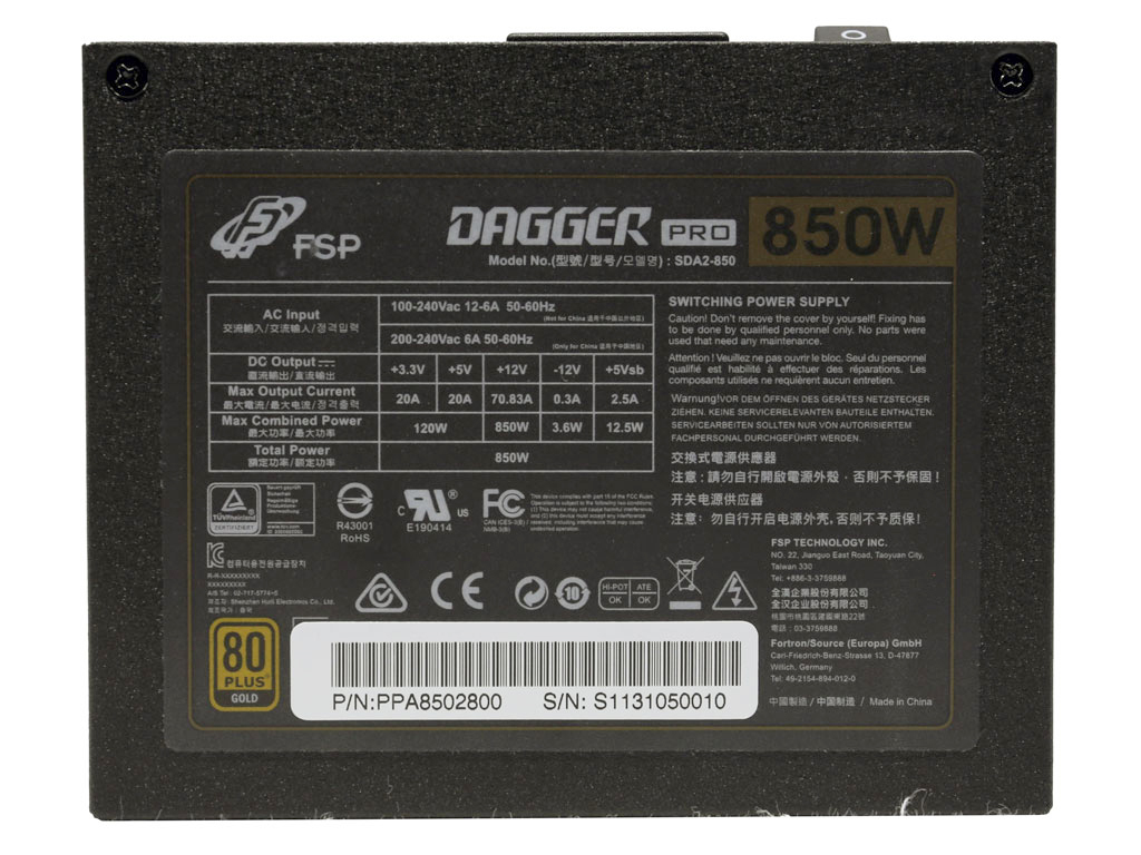

On the two sides, we find stickers with the model description. The power specifications label is on the bottom of the unit.
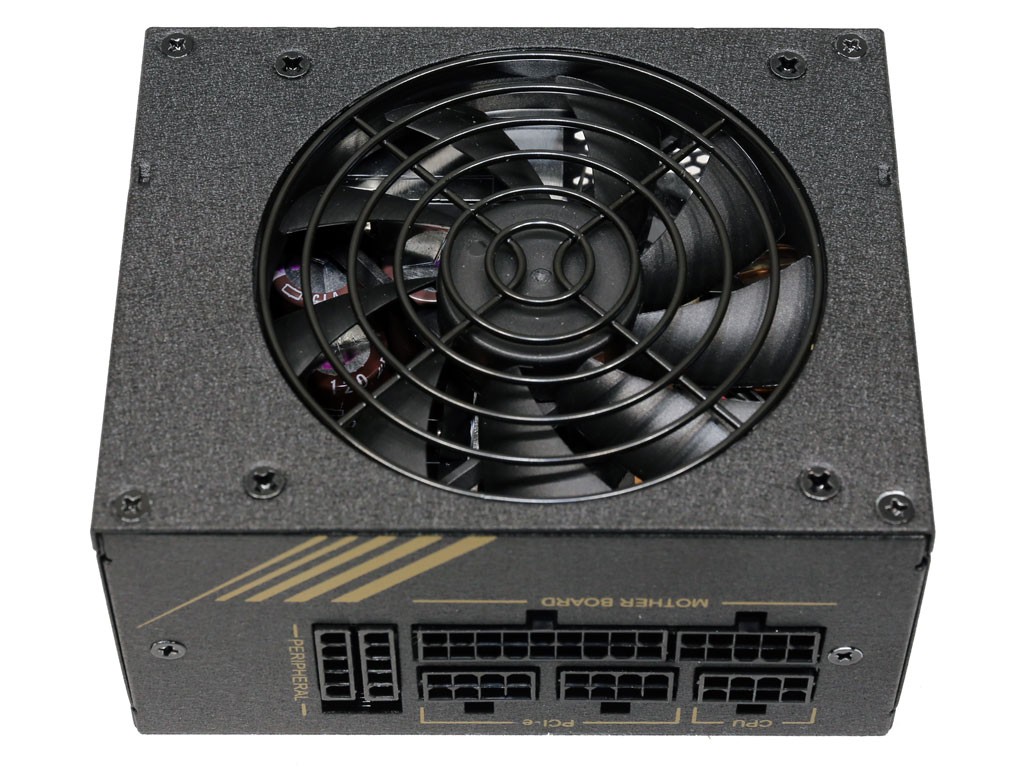
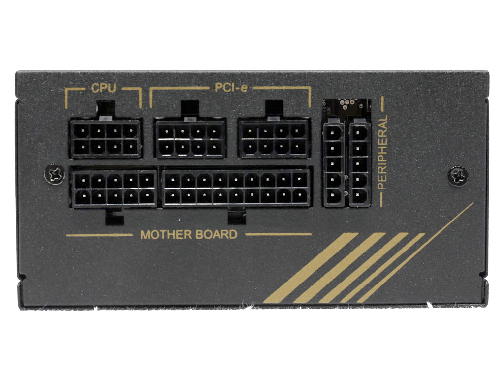
The modular panel has eight sockets, two for the 24-pin ATX connector, two for the peripheral cables, and three for the EPS and PCIe cables. Both EPS and all four PCIe connectors are available simultaneously since all three cables have two connectors.


The fan grille does not restrict airflow, which is a highly welcome feature in a high-capacity SFX power supply. Moreover, the unit's finish is matte, so it is both fingerprint proof and scratch-resistant.
Cables and Connectors
| Modular Cables | ||||
|---|---|---|---|---|
| Description | Cable Count | Connector Count (Total) | Gauge | In-Cable Capacitors |
| ATX connector 20+4 pin (500 mm) | 1 | 1 | 18–22AWG | No |
| 4+4 pin EPS12V (700 mm) / 8 pin EPS12V (700 mm) | 1 | 1 / 1 | 18AWG | No |
| 6+2 pin PCIe (500 mm) / 6+2 pin PCIe (500 mm) | 2 | 2 / 2 | 18AWG | No |
| SATA (350 mm+100 mm+100 mm) / 4-pin Molex (+100 mm) | 1 | 3 / 1 | 18AWG | No |
| SATA (350 mm+100 mm) / 4-pin Molex (+100 mm) / FDD (+100 mm) | 1 | 2 / 1 / 1 | 18–22AWG | No |
| AC Power Cord (1360 mm) - C13 coupler | 1 | 1 | 18AWG | - |


The cables are pretty long for an SFX PSU, which holds especially true for the ATX and EPS cables. Moreover, they are flat and "stealth," which means their gauges are black as well. There are no in-cable caps, which is ideal for most users, and the number of EPS and PCIe connectors is adequate.
I'm not too fond of the fact that both EPS connectors draw power from the same socket. While the only way to provide two of these connectors because of the small dimensions of the modular panel and low number of sockets, it is not safe if used with a power-hungry CPU.


I would like to see more SATA and 4-pin Molex connectors. Lastly, there is no need for the FDD connector. They should provide an additional 4-pin Molex connector instead and include an FDD adapter for the few who need it.
Component Analysis
Before reading this page, we strongly suggest a look at this article, which will help you better understand the insides of a PSU.| FSP Dagger Pro 850W Parts Description | |
|---|---|
| General Data | |
| Manufacturer (OEM) | FSP |
| PCB Type | Double-sided |
| Primary Side | |
| Transient Filter | 2x Y caps, 2x X caps, 3x CM chokes, and 1x MOV |
| Bridge Rectifier(s) | 2x HY GBU1506U (600 V, 3.2 A @ 100 °C w/o heatsink) |
| Inrush Current Protection | NTC Thermistor & Relay |
| APFC MOSFETs | 2x Vishay SiHG120N60E (600 V, 16 A @ 100 °C, Rds (on): 0.12 ohm) |
| APFC Boost Diode | 2x STMicroelectronics STPSC8H065 (650 V, 8 A @ 140 °C) |
| Bulk Cap(s) | 1x Nippon Chemi-Con (420 V, 120 uF, 2,000 h @ 105 °C, KHE) 2x United Chemi-Con (420 V, 150 uF each or 300 uf combined, 4–5,000 h @ 105 °C, CLA) |
| Main Switchers | 2x Infineon IPA80R310CE (800 V, 10.6 A @ 100 °C, Rds (on): 0.31 ohm) |
| Reset Switch | 1x Infineon IPD80R1K4CE (800 V, 2.3 A @ 100 °C, Rds (on): 1.4 ohm) |
| Combo APFC/Switching Controller | FSP MIA IC 6600 |
| Topology | Primary Side: APFC, Active Clamp Reset Forward Secondary Side: synchronous rectification & DC-DC converters |
| Secondary Side | |
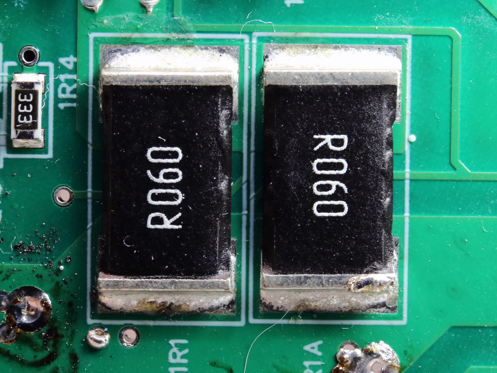
| +12 V MOSFETs | 6x Toshiba TPH1R306PL (60 V, 100 A, Rds (on): 1.34 mOhm) |
| +5 V & +3.3 V | DC-DC Converters: 4x Infineon BSC0902NS (30 V, 67 A @ 100 °C, Rds (on): 2.6 mOhm) PWM Controller(s): ANPEC APW7159C |
| Filtering Capacitors | Electrolytic: 1x Rubycon (3–6,000 h @ 105 °C, YXG), 2x Nippon Chemi-Con (4–10,000 h @ 105 °C, KY), 2x Nippon Chemi-Con (5–6,000 h @ 105°C, KZH Polymer: 1x APAQ 14x TEAPO |
| Supervisor IC | Weltrend WT7502R (OVP, UVP, SCP, PG) & FSP MIA IC 6601 (OCP) |
| Fan Model | Power Logic PLA09215B12H (92mm, 12V, 0.55A, double ball bearing fan) |
| 5VSB Circuit | |
| Rectifier(s) | 1x PFC PT20L80D SBR (80 V, 20 A) & 1x CET CEB02N7G FET (700 V, 1.3 A @ 100 °C, Rds (on): 6.75 ohm) |
| Standby PWM Controller | FSP MIA IC 6600 |

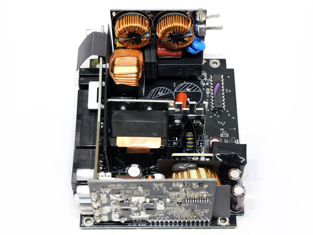


Despite the high capacity and small PCB, there is still plenty of available space because FSP used two large daughter boards to mount the DC-DC converters and transient/EMI filter. Moreover, instead of a single large bulk cap, FSP used three smaller ones. Finally, all heatsinks are small, especially those on the primary side. Good parts are used, but the build quality is not topnotch.
The transient/EMI filter stages have all the necessary parts, offering top EMI suppression on incoming and outgoing emissions.


A Metal Oxide Varistor (MOV) covered in heat shrink handles voltage surges, while an NTC thermistor and relay combination suppresses large inrush currents.

The bridge rectifiers are not bolted onto a heatsink, so they rely entirely on the cooling fan to remove their heat.

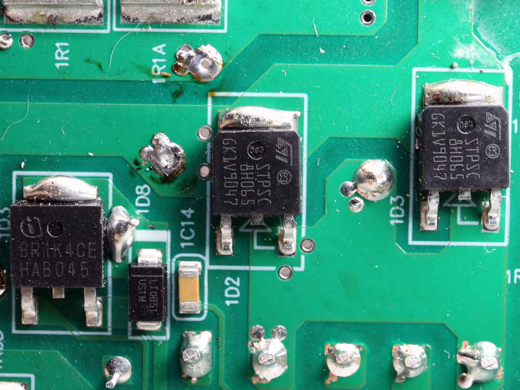
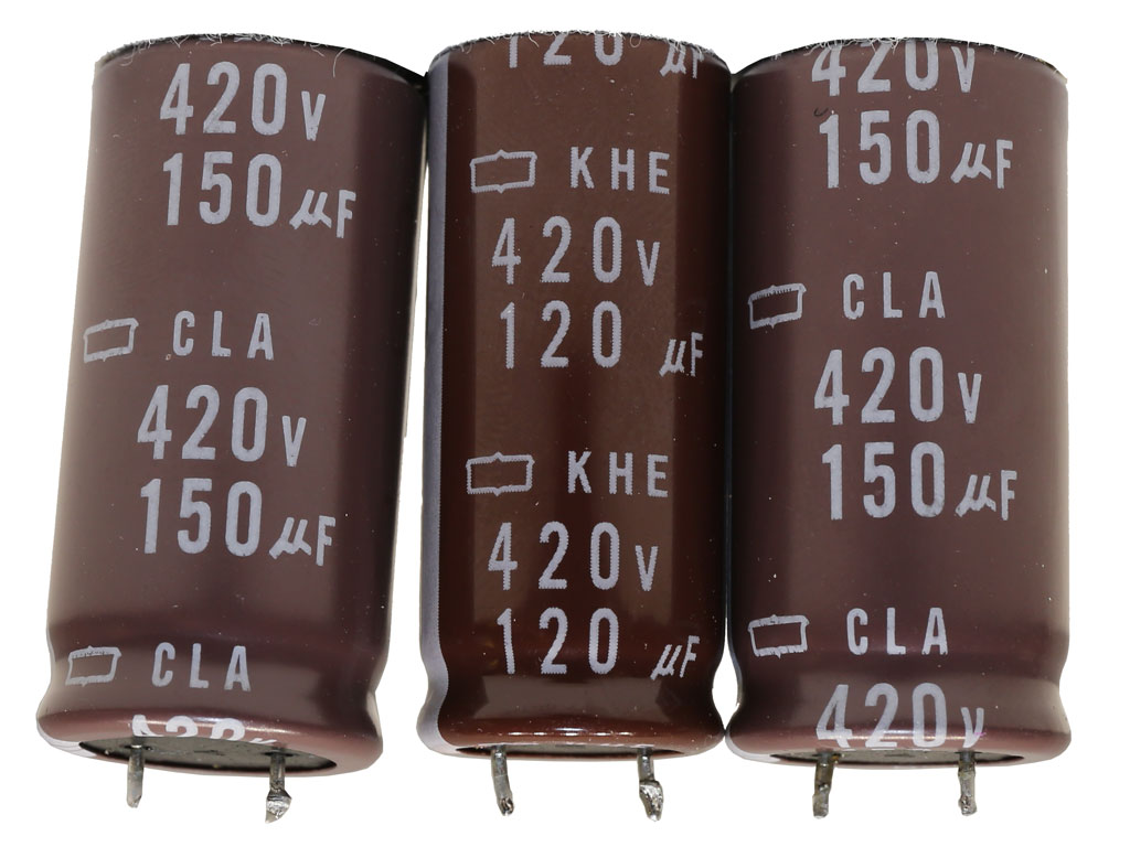
The APFC converter uses two Vishay FETs and the same number of STMicroelectronics boost diodes. The bulk caps are by Chemi-Con, and their combined total capacity is 420 uF.
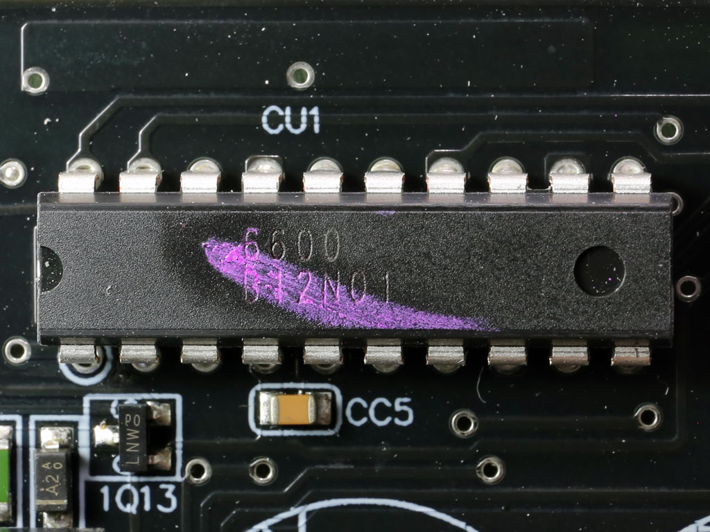
The APFC controller is a FSP MIA IC 6600. The same controller also handles the main FETs and the standby circuit which generates the 5VSB rail.
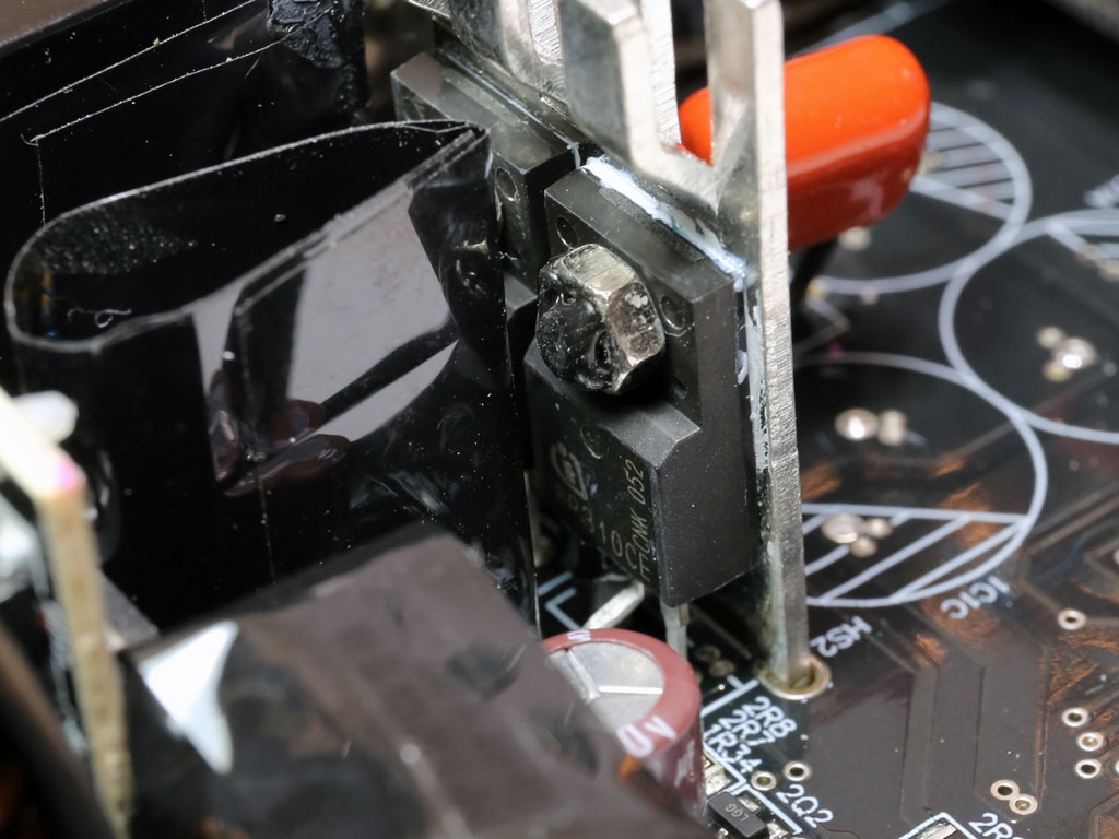
The main FETs are two Infineon IPA80R310CEs, and the reset switch is an Infineon IPD80R1K4CE.
The unit's main transformer is quite small.
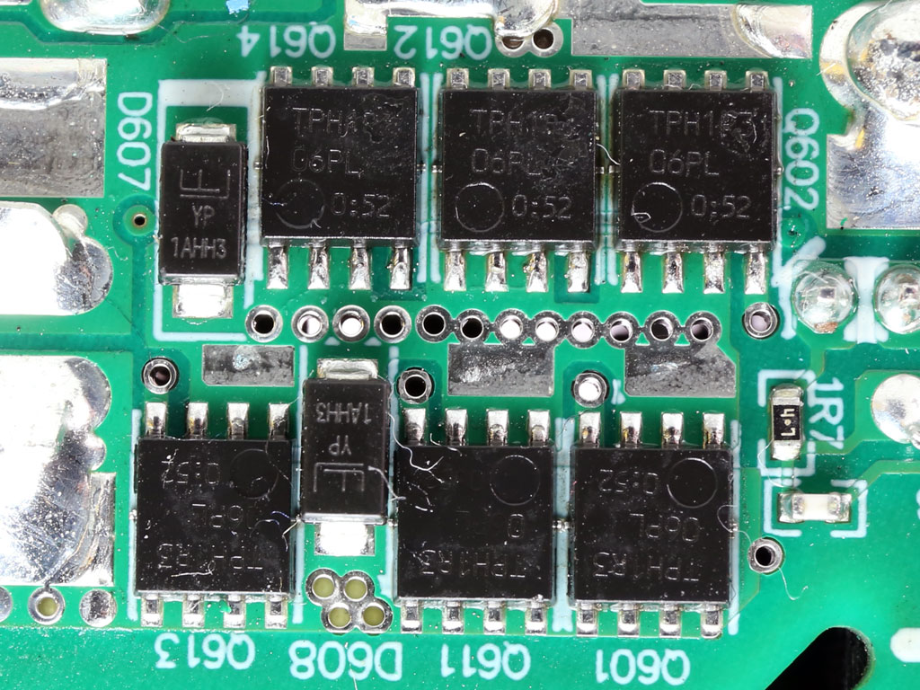
The FETs regulating the +12 V rail are installed on the solder side of the main PCB.


Two DC-DC converters generate the minor rails. They use four Infineon FETs, and their joint PWM controller is an Anpec APW7159C.
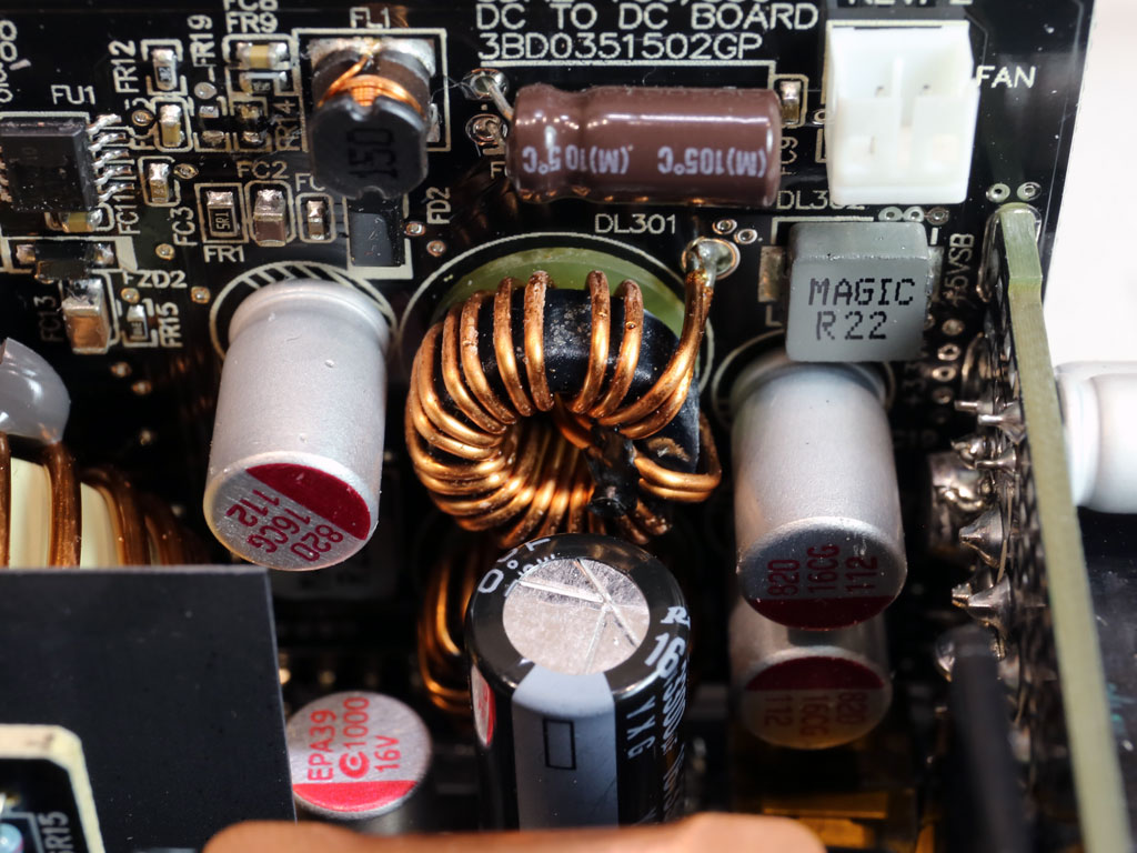


There aren't many electrolytic caps, but those installed are of high quality. Lots of Teapo polymer caps are also used.
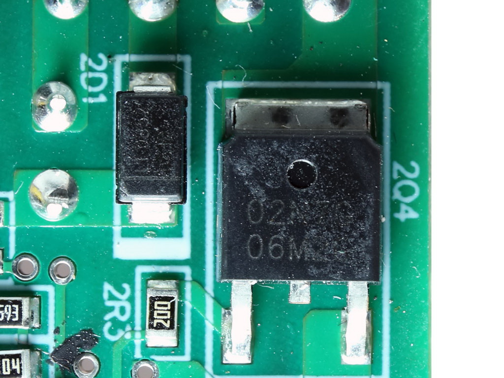
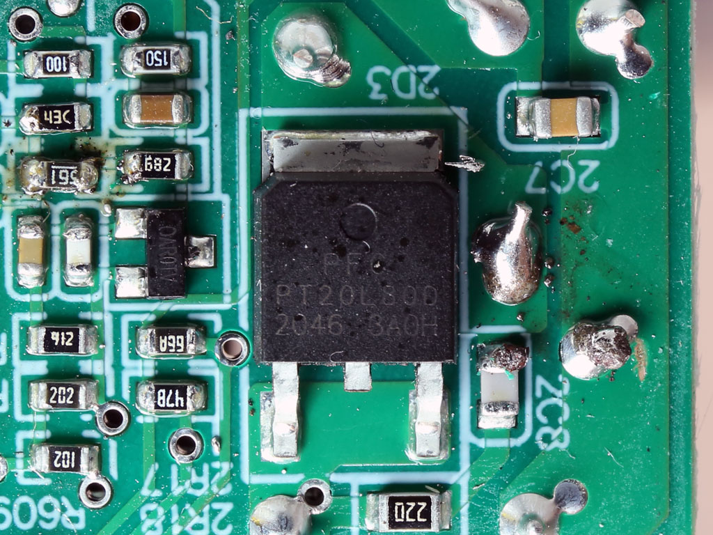
The 5VSB circuit uses a CET FET on its primary side and a PFC SBR on its secondary side.


The supervisor IC is a Weltrend WT7502R, which only provides the essential protection features. The FSP MIA IC 6601 provides OCP. The same IC also controls the +12 V and 3.3 V FETs.

Several polymer caps are installed on the face of the modular PCB. The supervisor IC along with a TPS54231 buck-converter IC are also installed here.


Soldering quality is mediocre. I expected better soldering from FSP.

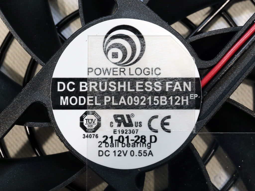
The cooling fan is by Power Logic and of high quality. It uses double ball-bearings and will, as such, last for a while even under high operating temperatures.
Test Setup

Our Patreon Silver Supporters can read articles in single-page format.
Apr 25th, 2024 19:33 EDT
change timezone
Latest GPU Drivers
New Forum Posts
- Best SSD for system drive (80)
- Dell Workstation Owners Club (3055)
- Core PL1 + GPU PL1 + Ring EDP OTHER (9)
- Which new games will you be buying? (315)
- BSOD if I touch the pcache offset voltage in throttlestop (i9-13900hx lenovo pro 7i) (23)
- Alphacool CORE 1 CPU block - bulging with danger of splitting? (16)
- How to check flatness of CPUs and coolers - INK and OPTICAL INTERFERENCE methods (112)
- TPU's Nostalgic Hardware Club (18464)
- Post your Cinebench 2024 score (450)
- Ubuntu 24.04 LTS released (2)
Popular Reviews
- Fractal Design Terra Review
- Thermalright Phantom Spirit 120 EVO Review
- Corsair 2000D Airflow Review
- Minisforum EliteMini UM780 XTX (AMD Ryzen 7 7840HS) Review
- ASUS GeForce RTX 4090 STRIX OC Review
- NVIDIA GeForce RTX 4090 Founders Edition Review - Impressive Performance
- ASUS GeForce RTX 4090 Matrix Platinum Review - The RTX 4090 Ti
- MSI GeForce RTX 4090 Suprim X Review
- MSI GeForce RTX 4090 Gaming X Trio Review
- Gigabyte GeForce RTX 4090 Gaming OC Review
Controversial News Posts
- Sony PlayStation 5 Pro Specifications Confirmed, Console Arrives Before Holidays (117)
- Windows 11 Now Officially Adware as Microsoft Embeds Ads in the Start Menu (107)
- NVIDIA Points Intel Raptor Lake CPU Users to Get Help from Intel Amid System Instability Issues (106)
- AMD "Strix Halo" Zen 5 Mobile Processor Pictured: Chiplet-based, Uses 256-bit LPDDR5X (101)
- US Government Wants Nuclear Plants to Offload AI Data Center Expansion (98)
- AMD's RDNA 4 GPUs Could Stick with 18 Gbps GDDR6 Memory (87)
- Developers of Outpost Infinity Siege Recommend Underclocking i9-13900K and i9-14900K for Stability on Machines with RTX 4090 (85)
- Windows 10 Security Updates to Cost $61 After 2025, $427 by 2028 (84)