 0
0
GIGABYTE 3D Galaxy II Review
Performance »Installation
The installation of the 3D Galaxy II was very quite simple. The hardest part in my opinion when it comes to installing a water cooler is getting all the parts placed and having the tubing the correct length. When it comes to "what goes where?", that's what the manual is for. There is plenty of detail in the manual that throughly describes the installation.
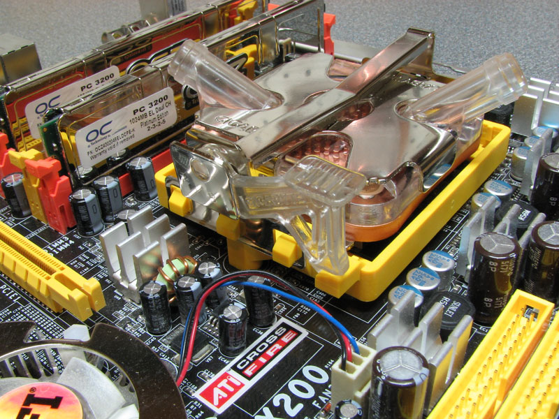
First thing I did was remove the motherboard from the case. This isn't completely necessary, however to show things better, I did so. When it comes to installing the unit on an Intel system, you will need to remove the motherboard from the chassis to attach the bottom bracket needed to mount the water block. The installation of the block on AMD based systems is the same as any other cooler using the normal retention module. Simply line the block up, and clip on the retention module and you're done.


When I came to the installation of the radiator, the first thing I was going to bump into was that the radiator was in the way of the CrossFire dongle cable. Little did I think to read the instructions where it showed the above mount that is provided to attach the radiator to the PSU screws. A very good idea GIGABYTE had with it, and it solved the issue of the CrossFire dongle cable being in the way and also give the kit a far great compatibility with more cases.
The way it works is simple, a 90 degree bracket attaches to the radiator and then to the bottom two screws used to mount the PSU to the chassis. This gives the radiator a bit of clearance from the chassis, and also improves compatibility with cases. It wouldn't matter if the rear fan of the case was 120mm or even 80mm as the radiator doesn't even attach to that part of the case.


The wiring of the 3D Galaxy II is fairly straightforward. First thing I did was put in the pump wiring harness in. The power header cord for the switch in the case needs to plug into the harness, and then the harness into the board. This is for the safety feature the pump has implemented. The fan controller is next - It simply hooks to a fan header on the board, then the variable controller switch plugs into it along with the radiator fan.


The rest of the installation is running the tubing, and cutting it to size. Not all layouts are going to be the same, but the order in which the parts go into the loop will be. Some cases will require less piping, and some will need more. All depends on where you put the pump, how you have the pipes going to radiator and so on.


Once everything is in place, and the connections were double checked, I started to add the coolant. I used another PSU (Because I like to be lazy) to turn the pump on, instead of unplugging everything in my case and manually turning the PSU on. Slowly adding the coolant, the pump will circulate it. You will have to move some things around to get the air out, such as putting the radiator on its side. Once all the air seems to be bleed, I let the system leak test for a hour or so before booting the system.
May 4th, 2024 05:57 EDT
change timezone
Latest GPU Drivers
New Forum Posts
- RX 6800 causing stuttering when typing text (Low 2D/IDLE Clocks?) (4)
- Why does my PC shut down even though it's connected to a UPS? (77)
- Alphacool CORE 1 CPU block - bulging with danger of splitting? (79)
- fastest usb cable /transfer (17)
- Unigine Heaven 4.0 Benchmark Scores Part 2 (929)
- What's your latest tech purchase? (20429)
- What is your startup time for GIMP? (3)
- Keysfan (12)
- NASA Achieves milestone Solid State Battery (223)
- Change GPU or PSU ? Games look cryspy and sharp with microsuttering (7)
Popular Reviews
- Finalmouse UltralightX Review
- Meze Audio LIRIC 2nd Generation Closed-Back Headphones Review
- ASRock NUC BOX-155H (Intel Core Ultra 7 155H) Review
- Montech Sky Two GX Review
- Gigabyte GeForce RTX 4070 Ti Super Gaming OC Review
- Upcoming Hardware Launches 2023 (Updated Feb 2024)
- HYTE THICC Q60 240 mm AIO Review
- Alienware Pro Wireless Gaming Keyboard Review
- Ugreen NASync DXP4800 Plus Review
- AMD Ryzen 7 7800X3D Review - The Best Gaming CPU
Controversial News Posts
- Intel Statement on Stability Issues: "Motherboard Makers to Blame" (236)
- Windows 11 Now Officially Adware as Microsoft Embeds Ads in the Start Menu (167)
- AMD to Redesign Ray Tracing Hardware on RDNA 4 (118)
- Sony PlayStation 5 Pro Specifications Confirmed, Console Arrives Before Holidays (117)
- AMD's RDNA 4 GPUs Could Stick with 18 Gbps GDDR6 Memory (114)
- NVIDIA Points Intel Raptor Lake CPU Users to Get Help from Intel Amid System Instability Issues (106)
- AMD "Strix Halo" Zen 5 Mobile Processor Pictured: Chiplet-based, Uses 256-bit LPDDR5X (103)
- AMD Ryzen 9 7900X3D Now at a Mouth-watering $329 (103)