 50
50
Gigabyte UD1000GM PG5 1000 W Review - The First PCIe 5.0 PSU
Teardown & Components »Photos

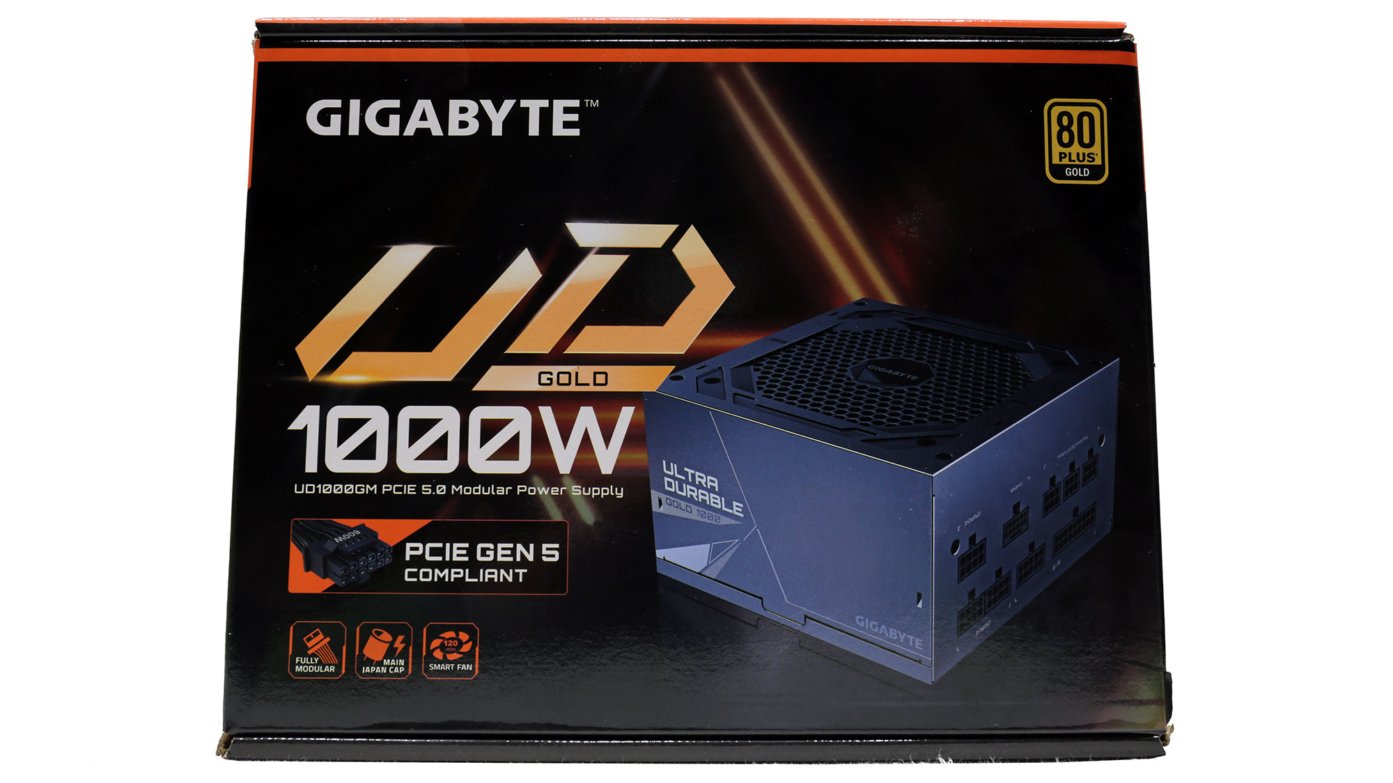

The box is small because of the PSU's compact dimensions. At the face, mention is made of the PCIe Gen 5 compatibility, but Gigabyte forgot to replace the ATX v2.31 mention on the back with ATX v3.0. The unit is listed as ATX v3.0 compatible on the product web page.


Foam spacers surround the PSU, providing good protection.


The bundle only includes the necessary bits and bobs: a user manual, fixing bolts, the modular cables, and the AC power cord.


At the face of the PSU is the power switch and AC receptacle. There is no switch to toggle the semi-passive operation on/off.


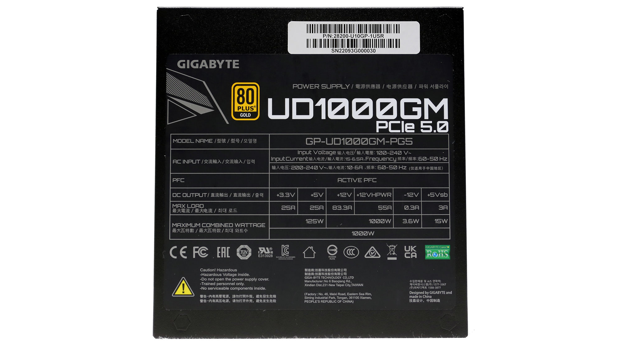
The power specifications label is on the bottom of the PSU, which it covers nearly entirely.


Including the 12VHPWR socket, the modular board has nine sockets.

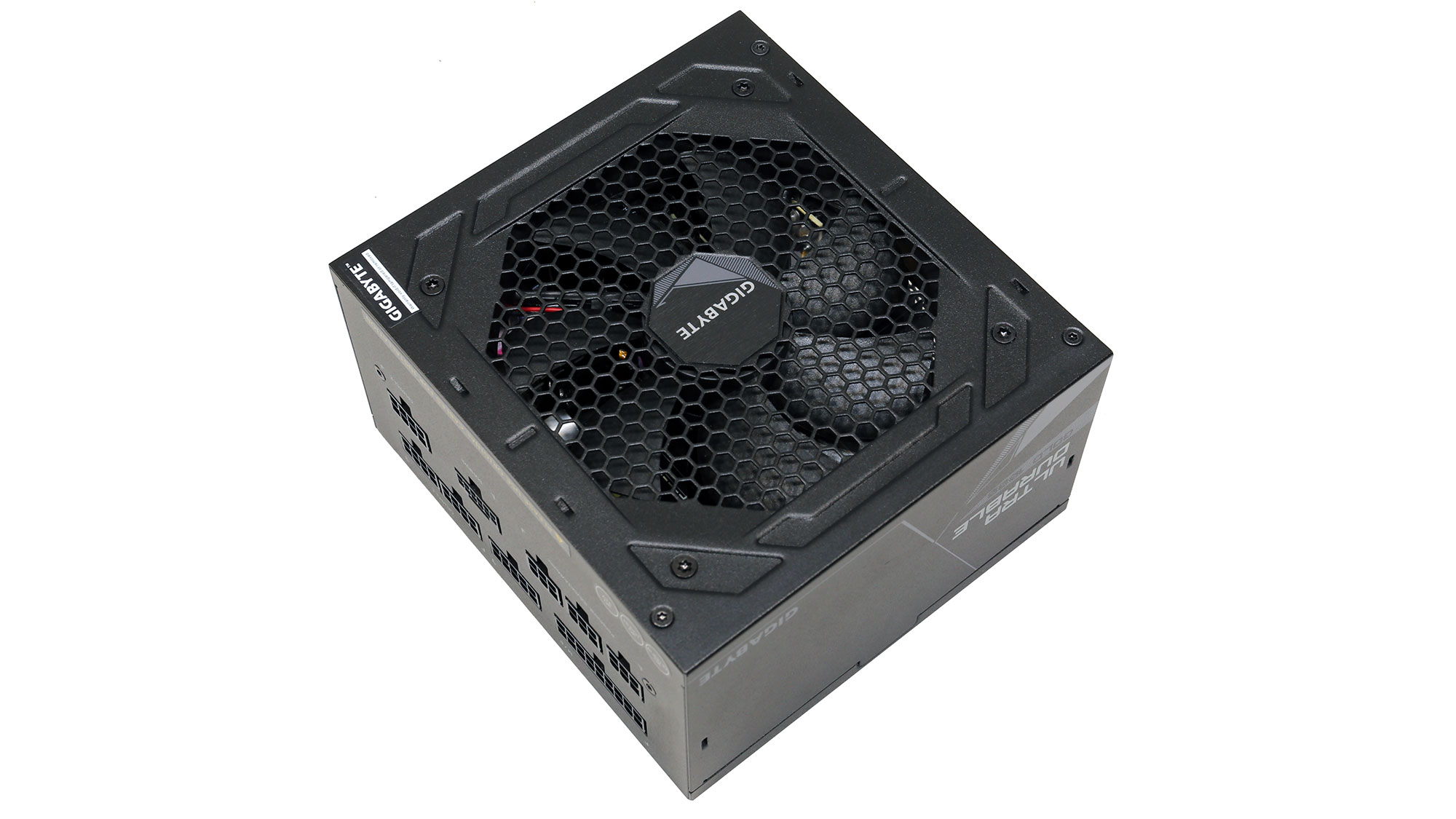
At only 140 mm long, this PSU is compact.
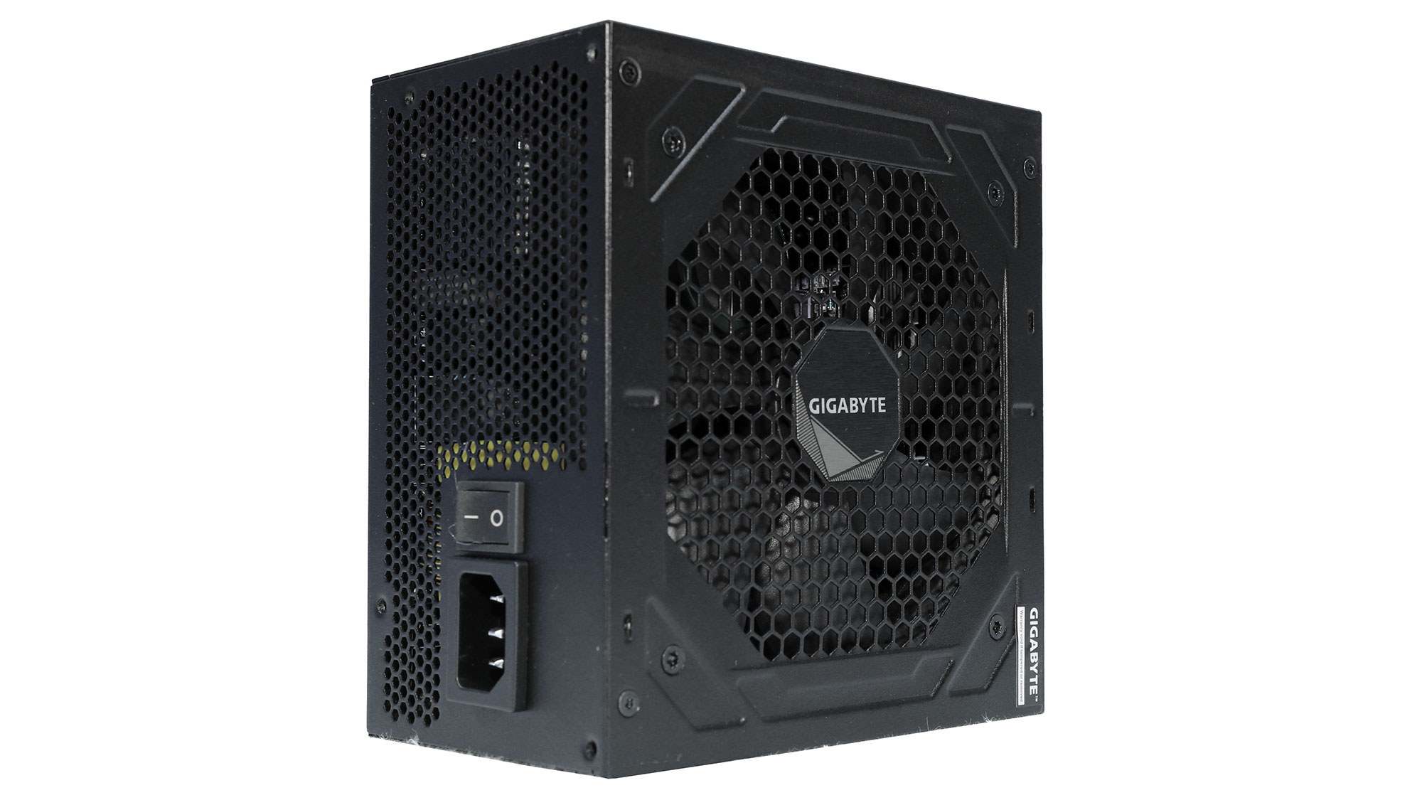
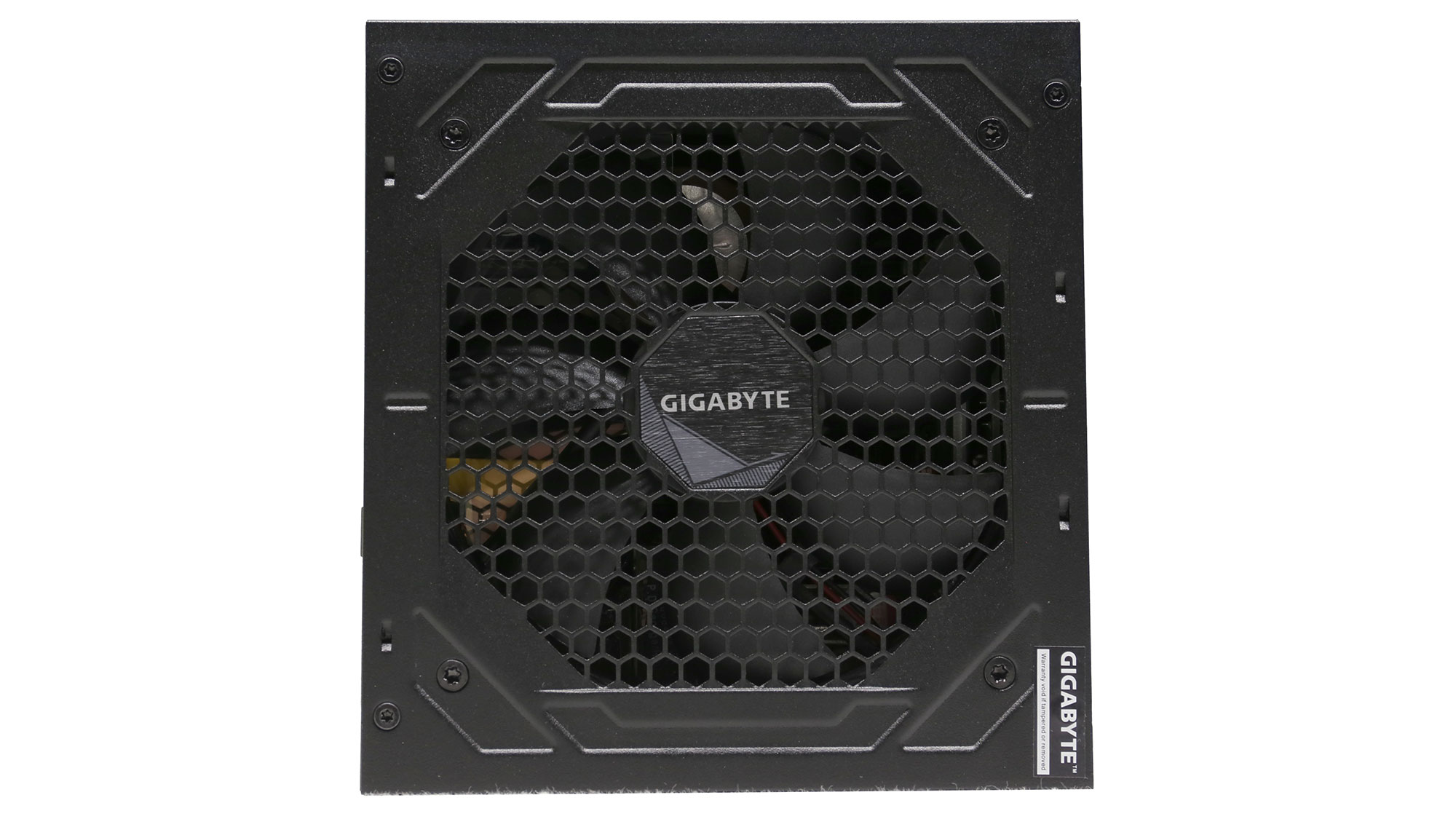
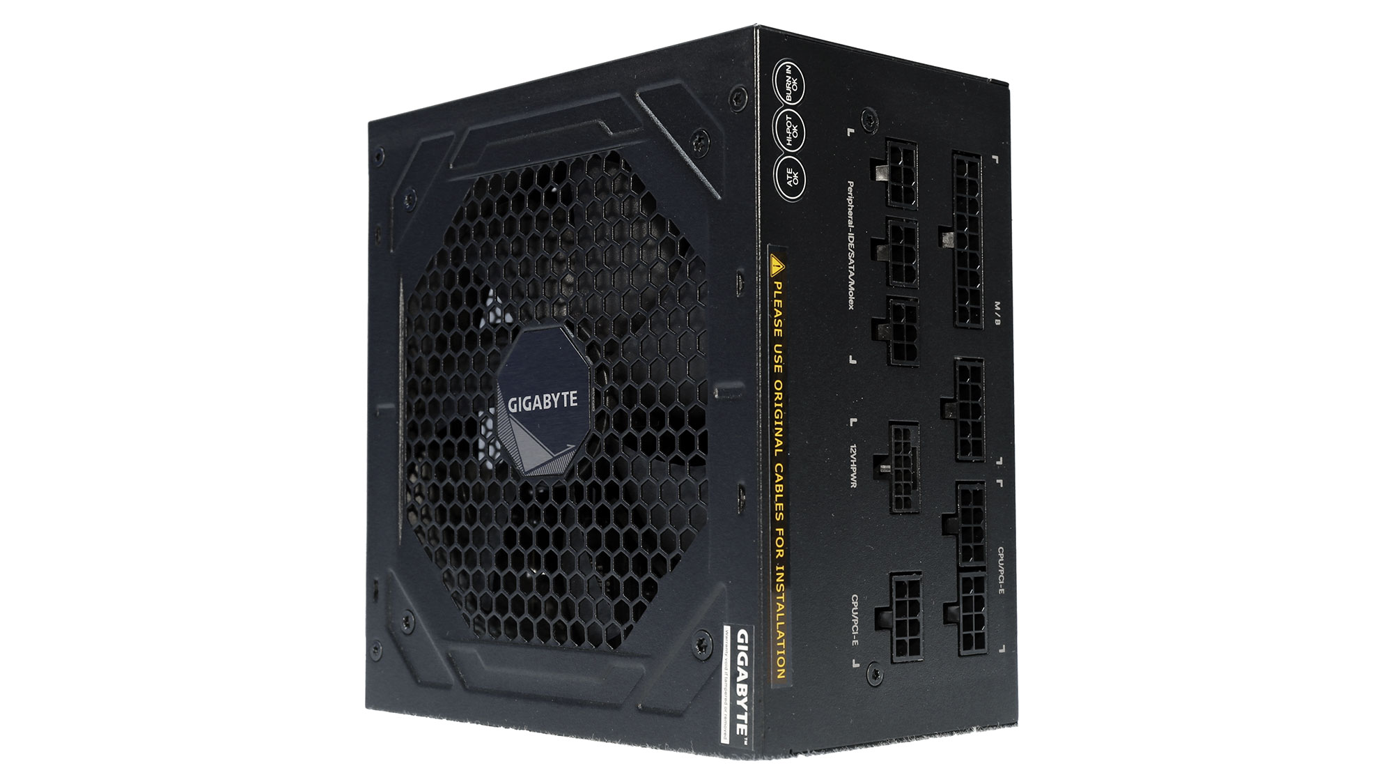
Some more photos of the PSU from various angles.
Cables and Connectors
| Modular Cables | ||||
|---|---|---|---|---|
| Description | Cable Count | Connector Count (Total) | Gauge | In-Cable Capacitors |
| ATX Connector 20+4 pin (610 mm) | 1 | 1 | 18AWG | No |
| 4+4 pin EPS12V (600 mm+200 mm) | 1 | 2 | 18AWG | No |
| 16 pin PCIe 5.0 (700 mm) | 1 | 1 | 16AWG | No |
| 6+2 pin PCIe (600 mm+150 mm) | 2 | 4 | 18AWG | No |
| SATA (600 mm+150 mm+150 mm+150 mm) | 2 | 8 | 18AWG | No |
| 4-pin Molex (500 mm+115 mm+115 mm) / FDD (+150 mm) | 1 | 3 / 1 | 18AWG | No |
| AC Power Cord (1400 mm) - C13 coupler | 1 | 1 | 16AWG | - |


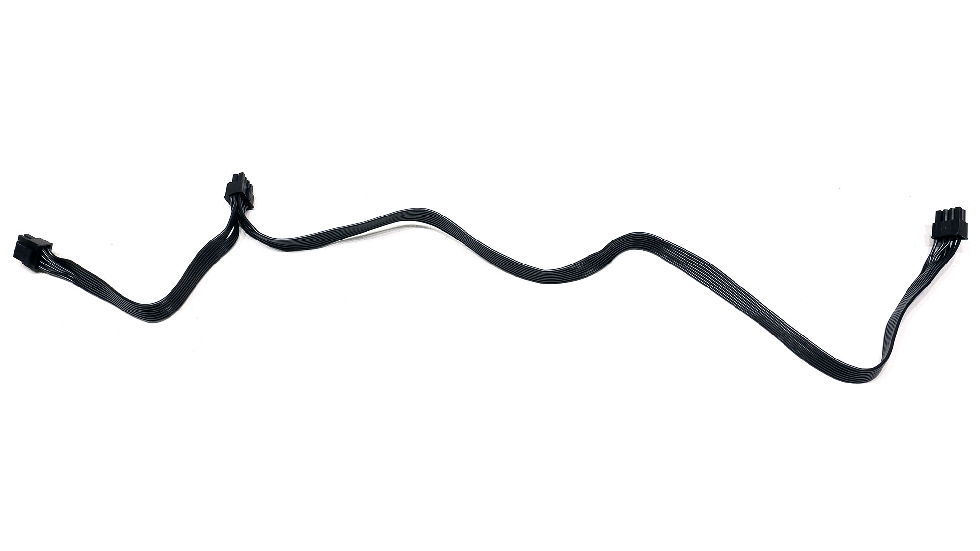

Both EPS connectors are on the same cable, so utilizing them fully won't be possible. Each EPS connector should be on its own dedicated cable. Moreover, it would be nice to see three PCIe cables instead of two.


There is no need for an FDD adapter, and the 4-pin Molex connectors should at least be 150 mm apart.

The AC power cord.
Apr 25th, 2024 17:24 EDT
change timezone
Latest GPU Drivers
New Forum Posts
- TPU's Nostalgic Hardware Club (18463)
- Ubuntu 24.04 LTS released (0)
- im new to throttelstop and i think i messed it up by copying others any hints would be very much aprreciated (2)
- Ryzen Owners Zen Garden (7243)
- What software are you using to monitor CPU temps during gaming session? (15)
- ROG Strix LC III 360 ARG AIO What should the pump speed be? (4)
- Ghetto Mods (4322)
- Legion Pro 7i, i9-13900HX. PL2 limit reason in log file (0)
- Alphacool CORE 1 CPU block - bulging with danger of splitting? (15)
- What are you playing? (20528)
Popular Reviews
- Fractal Design Terra Review
- Thermalright Phantom Spirit 120 EVO Review
- Corsair 2000D Airflow Review
- Minisforum EliteMini UM780 XTX (AMD Ryzen 7 7840HS) Review
- ASUS GeForce RTX 4090 STRIX OC Review
- NVIDIA GeForce RTX 4090 Founders Edition Review - Impressive Performance
- ASUS GeForce RTX 4090 Matrix Platinum Review - The RTX 4090 Ti
- MSI GeForce RTX 4090 Suprim X Review
- MSI GeForce RTX 4090 Gaming X Trio Review
- Gigabyte GeForce RTX 4090 Gaming OC Review
Controversial News Posts
- Sony PlayStation 5 Pro Specifications Confirmed, Console Arrives Before Holidays (116)
- Windows 11 Now Officially Adware as Microsoft Embeds Ads in the Start Menu (106)
- NVIDIA Points Intel Raptor Lake CPU Users to Get Help from Intel Amid System Instability Issues (106)
- AMD "Strix Halo" Zen 5 Mobile Processor Pictured: Chiplet-based, Uses 256-bit LPDDR5X (101)
- US Government Wants Nuclear Plants to Offload AI Data Center Expansion (98)
- AMD's RDNA 4 GPUs Could Stick with 18 Gbps GDDR6 Memory (87)
- Developers of Outpost Infinity Siege Recommend Underclocking i9-13900K and i9-14900K for Stability on Machines with RTX 4090 (85)
- Windows 10 Security Updates to Cost $61 After 2025, $427 by 2028 (84)