 15
15
Gigabyte UD750GM 750 W Review - No Lightning This Time
(15 Comments) »Introduction

After reviewing all other Gigabyte UD models, it's time for the UD750GM to get on the test bench. Bad memories from when I last reviewed a Gigabyte 750 W unit (P750GM) still haunt me, but a long time has passed since, and MEIC has improved the platform. For only ten dollars more, you can get a Corsair RM750x (2021 model) or Corsair RM750, so the UD750GM has to do a lot right to convince me it is a good choice for the money. Like the other UD PSUs, I plan to give it an extra-hard time to figure out whether it works correctly under all conditions, and I will compare its performance to the "legendary" P750GM.
Members of the UD line use improved P-GM platforms, with the 1000 W unit the first to boast ATX v3.0 compatibility primarily because of its 12+4 pin PCIe connector. However, in my new transient tests, it failed to meet all requirement of the specification. The UD750GM is not ATX v3.0 compatible, so it won't have to deal with those additional tests. At some point, however, Gigabyte will have to upgrade the 750 W and 850 W UD units to make them future-proof. We are in a transitory period right now. Most manufacturers are already working hard on upgraded PSUs with the 12VHPWR connector, which will be the standard for upcoming GPUs. Some board partners might insist on the 6+2 pin connectors for a bit longer, but everyone will eventually have to adopt 12VHPWR, so you better have a PSU that has one or you will have to rely on adapters, which is a bad idea for high-power applications.
Specifications
| Features & Specifications | |
|---|---|
| Max. DC Output | 750 W |
| PFC | Active PFC |
| Efficiency: 80 PLUS | Gold |
| Efficiency: Cybenetics | 115 V: Platinum (89–91%) 230 V: Platinum (91–93%) |
| Noise | Cybenetics Standard++ (30–35 dBA) |
| Modular | Yes (fully) |
| Intel C6/C7 Power State Support | Yes |
| Operating Temperature | 0–40 °C |
| Protections | Over Voltage Protection Under Voltage Protection Over Power Protection Over Temperature Protection Over Current Protection Short Circuit Protection |
| Cooling | 120 mm rifle bearing fan (D12SH-12) |
| Semi-Passive Operation | Yes |
| Dimensions (W x H x D) | 150 x 85 x 140 mm |
| Weight | 1.42 kg (3.13 lb) |
| Compliance | ATX12Vv2.31, EPS 2.92 |
| Warranty | 5 years |
| Price at Time of Review (excl. VAT) | US$130 |
| Power Specifications | |||||||
|---|---|---|---|---|---|---|---|
| Rail | 3.3 V | 5 V | 12 V | 5 VSB | -12 V | ||
| Max. Power | 20 A | 20 A | 61 A | 3 A | 0.3 A | ||
| 105 W | 732 W | 15 W | 3.6 W | ||||
| Total Max. Power | 750 W | ||||||
Photos

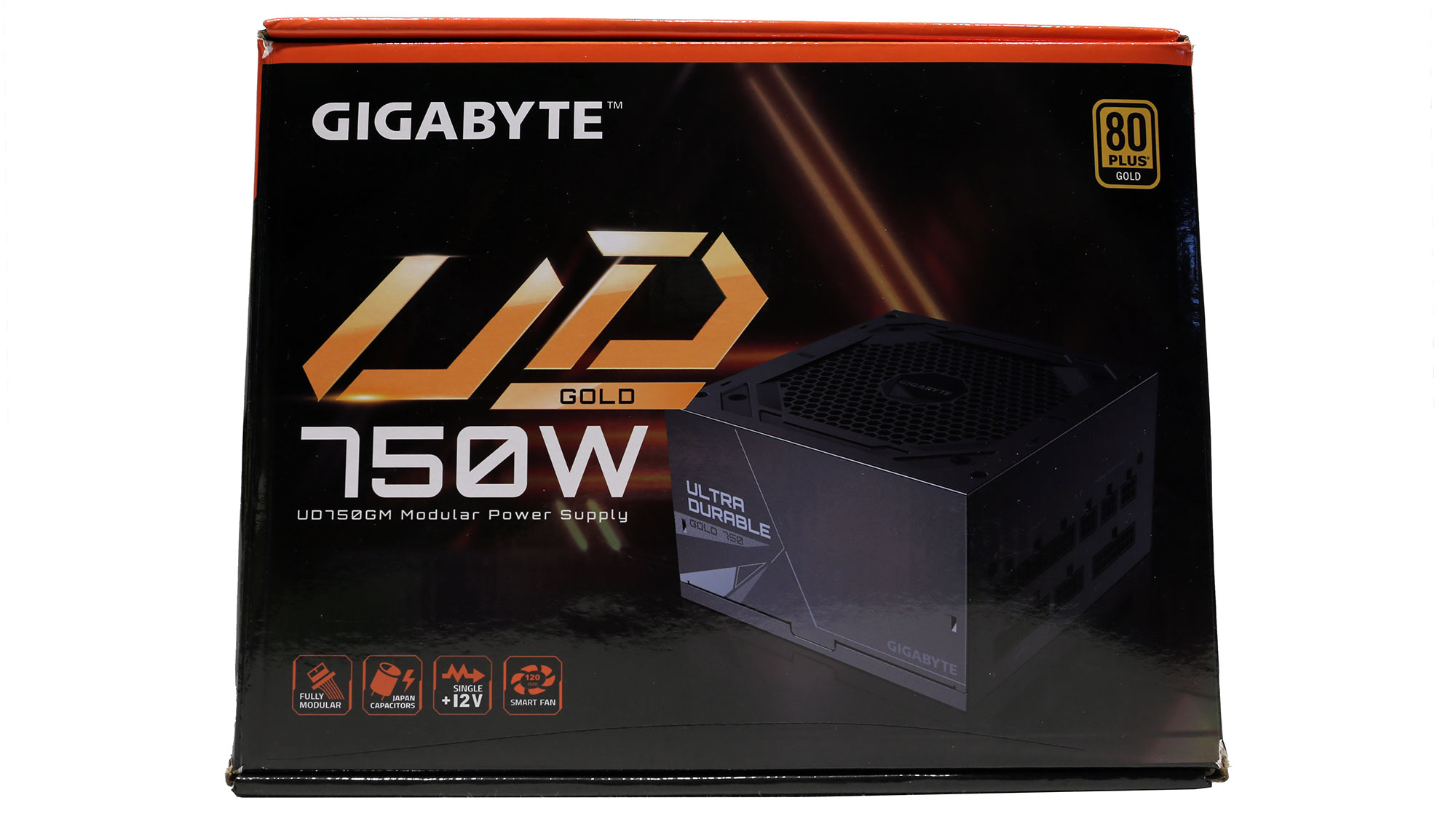
At the face of the small box is a photo of the PSU with the modular panel exposed. As per usual, more information is available on the back.
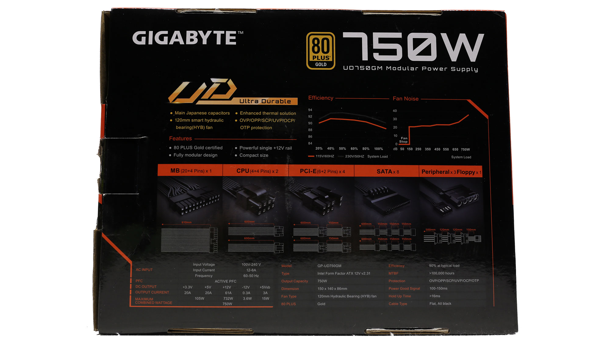
Protection inside the box is good, with packing foam surrounding the product. As a cost-saving measure, Gigabyte has excluded the pouch for the modular cables.


The bundle includes the modular cables and AC power cord, set of fixing bolts, and user manual.


The exterior design is identical to that of the 850 W unit.


The power specifications label covers the bottom almost entirely.
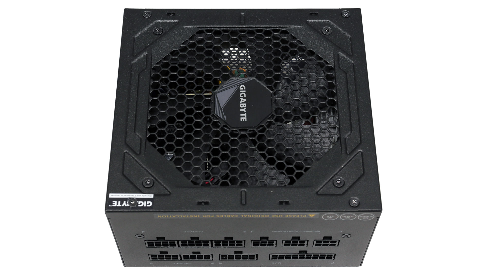

The modular board has ten sockets. A note here mentions that you should only use the original cables. Many people think that modular cables are electrically compatible with all PSUs, which is false. While connector sizes on the load side are standardized, those on the PSU are not, so make sure not to mix modular cables.

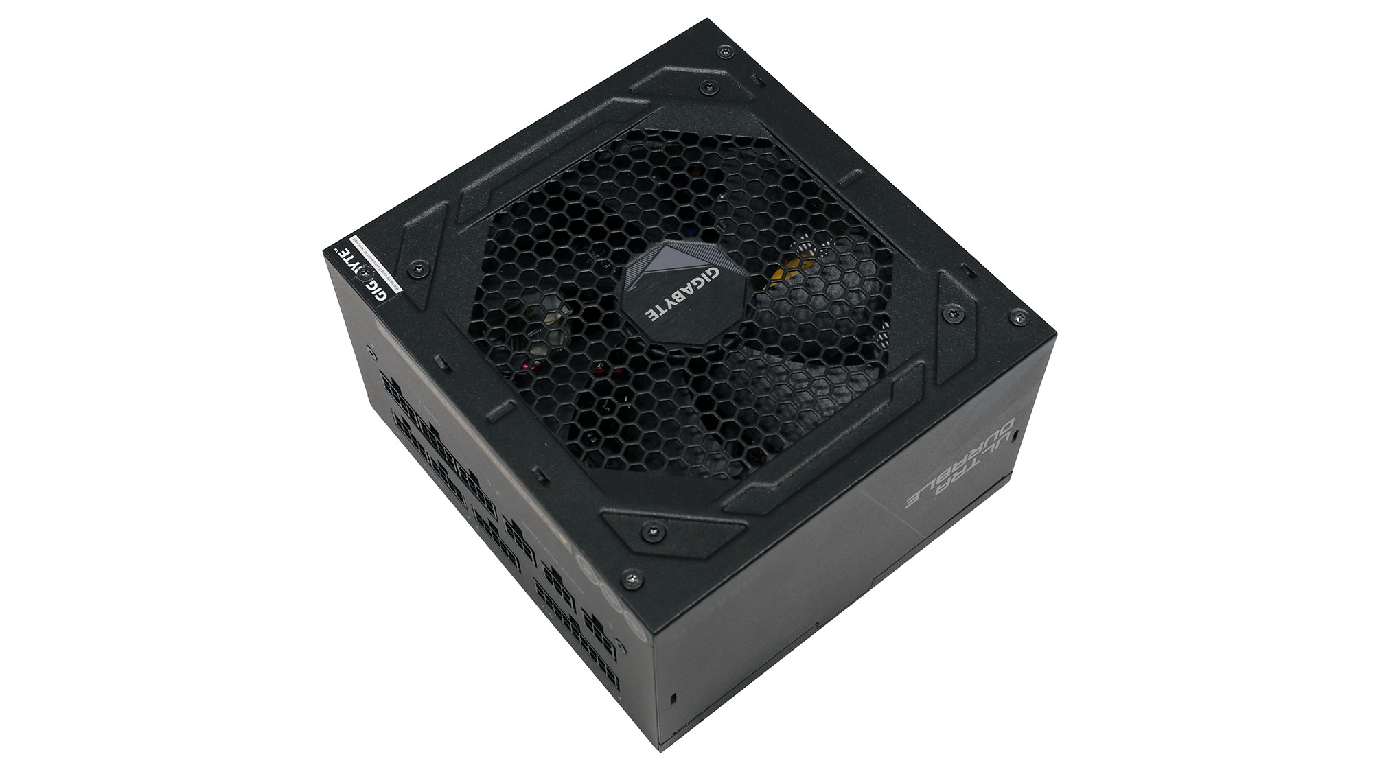
At only 140 mm long, this PSU is compact.
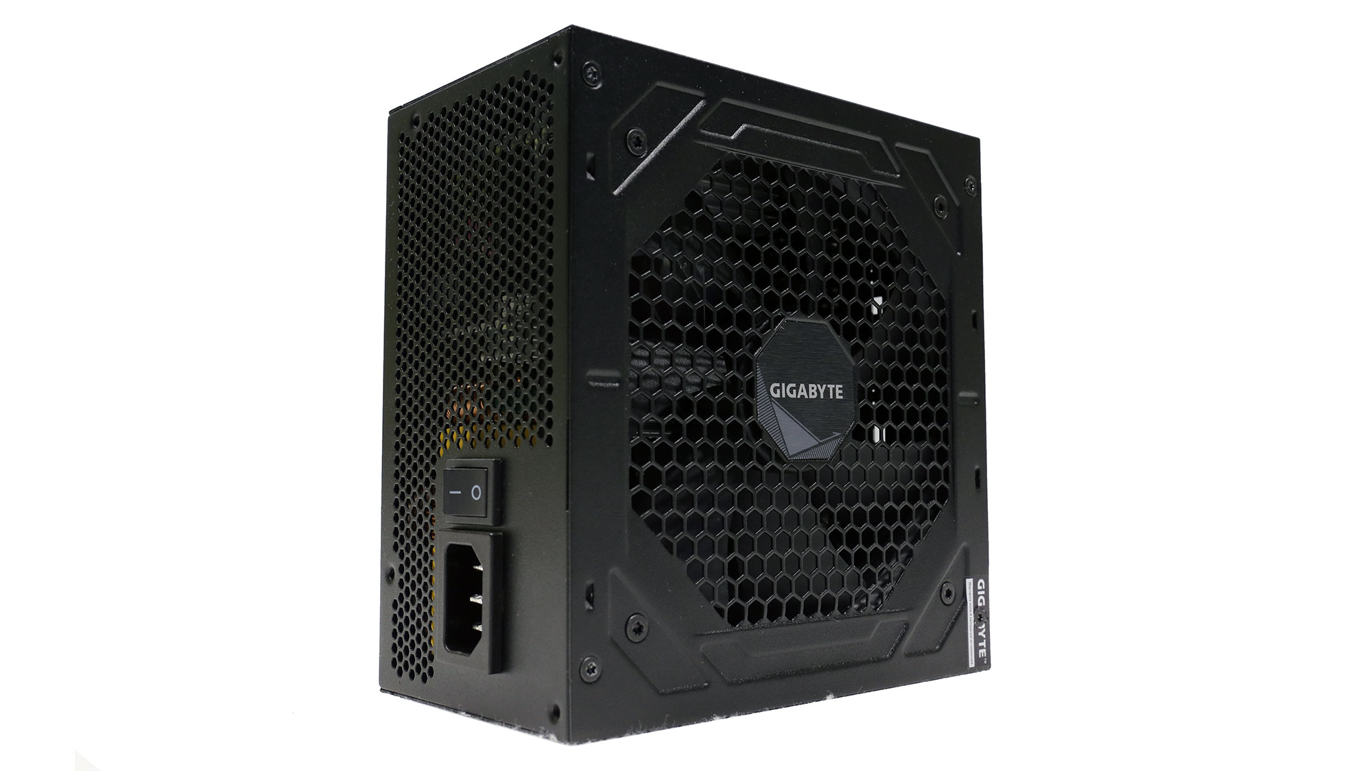
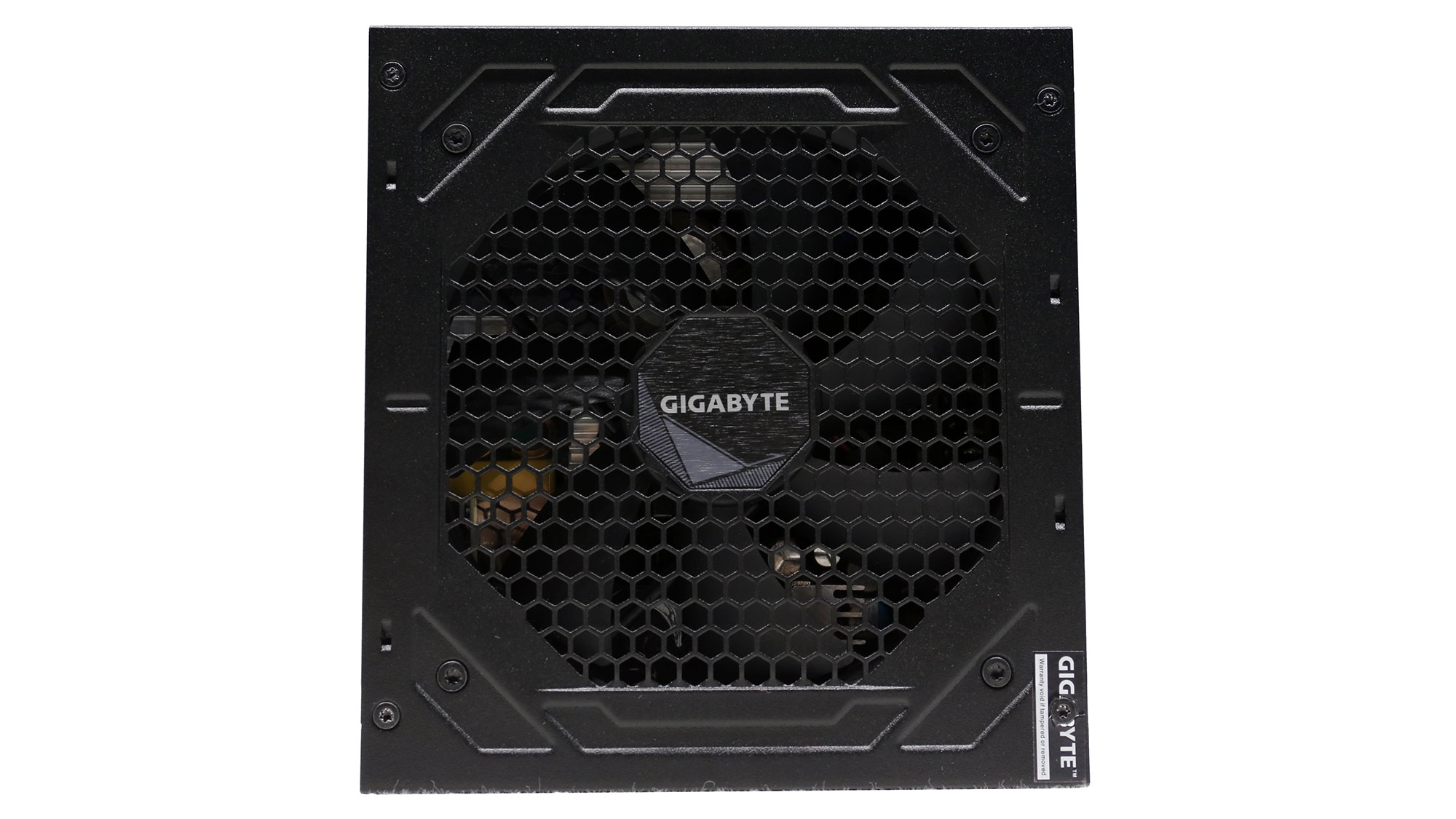

Here are some more photos of the PSU from various angles.
Cables and Connectors
| Modular Cables | ||||
|---|---|---|---|---|
| Description | Cable Count | Connector Count (Total) | Gauge | In-Cable Capacitors |
| ATX connector 20+4 pin (610 mm) | 1 | 1 | 18AWG | No |
| 4+4 pin EPS12V (600 mm) | 2 | 2 | 18AWG | No |
| 6+2 pin PCIe (600 mm+150 mm) | 2 | 4 | 18AWG | No |
| SATA (600 mm+150 mm+150 mm+150 mm) | 2 | 8 | 18AWG | No |
| 4-pin Molex (500 mm+115 mm+115 mm) / FDD (+150 mm) | 1 | 3 / 1 | 18AWG | No |
| AC Power Cord (1400 mm) - C13 coupler | 1 | 1 | 16AWG | No |
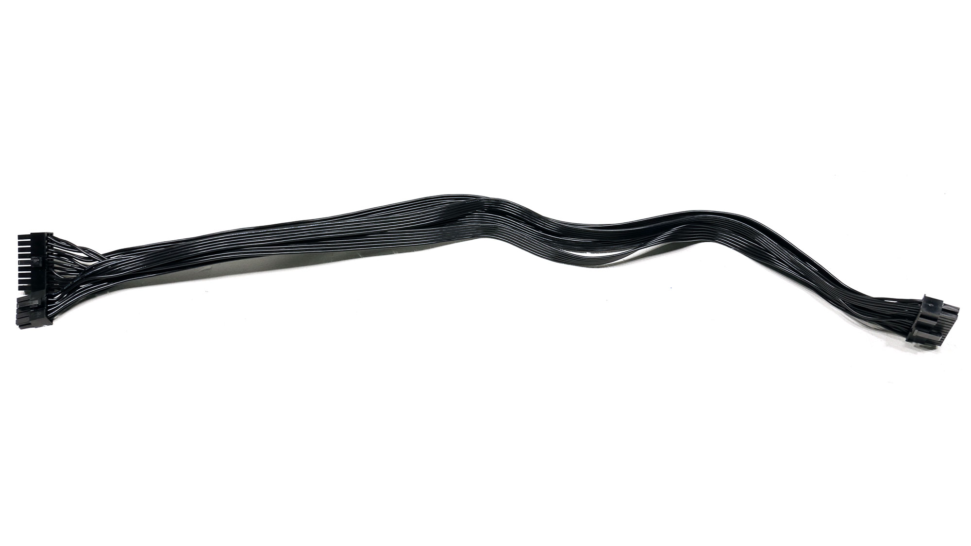


The ATX cable is longer than the EPS ones, which caught my attention in the review of the 850 W unit as well. I want both EPS cables to be 650 mm long. The number of available connectors is satisfactory, but the PSU lacks a 12+4 pin PCIe connector, which will replace the current PCIe connector in the future.
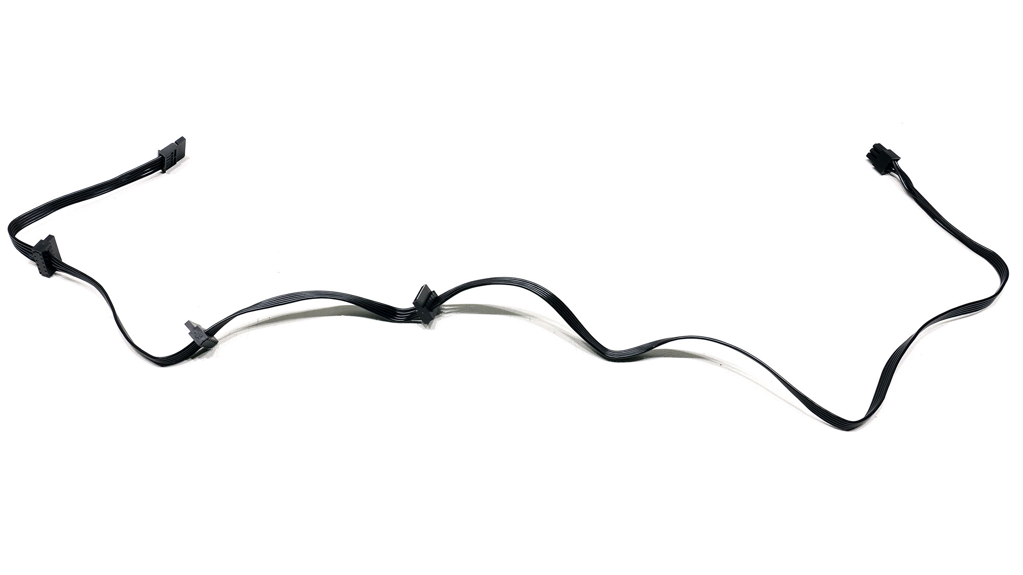

The number of peripheral connectors is adequate, but there is no need for a floppy connector. Moreover, the distance between peripheral connectors is only 115 mm.
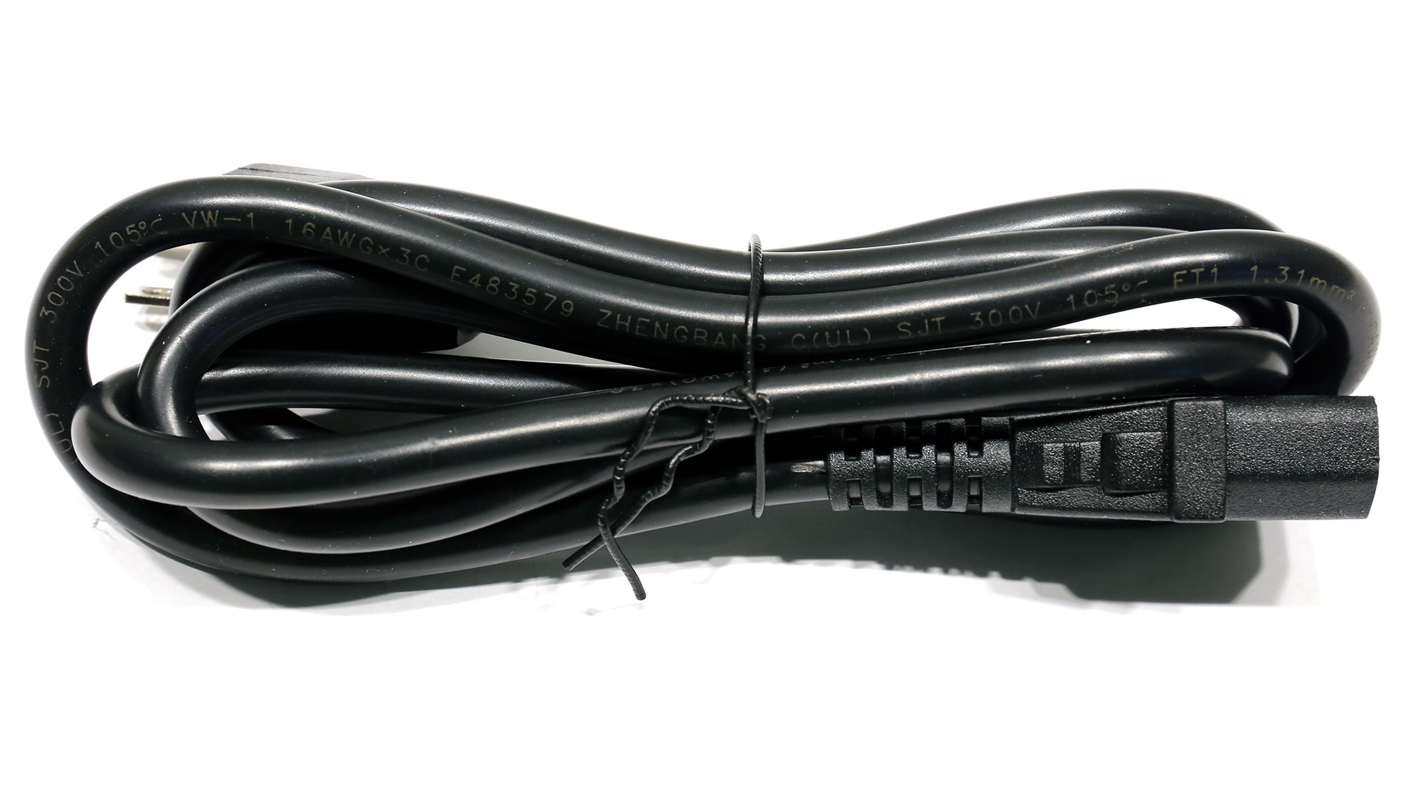
The PSU came with a US power cord.
Component Analysis
Before reading this page, we strongly suggest looking at this article, which will help you better understand the insides of a PSU.| Gigabyte UD750GM Parts Description | |
|---|---|
| General Data | |
| Manufacturer (OEM) | MEIC |
| PCB Type | Double-Sided |
| Primary Side | |
| Transient Filter | 4x Y caps, 2x X caps, 2x CM chokes, 1x MOV, 1x Chipown PN8200 (Discharge IC) |
| Bridge Rectifier(s) | 2x GBU1506 (800 V, 15 A @ 100°C) |
| Inrush Current Protection | NTC thermistor & relay |
| APFC MOSFETs | 2x NCE Power NCE65TF099F (650 V, 24 A @ 100°C, Rds (on): 0.109 ohm) |
| APFC Boost Diode | 1x JF SC0665 (650 V, 6 A @ 175°C) |
| Bulk Cap(s) | 1x Nippon Chemi-Con (400 V, 680 uF, 2,000 h @ 105°C, KMW) |
| Main Switchers | 2x NCE Power NCE65TF099F (650 V, 24 A @ 100°C, Rds (on): 0.109 ohm) |
| APFC Controller | Champion CM6500UNX |
| Switching Controller | Champion CM6901X |
| Topology | Primary Side: APFC, half-bridge & LLC converter Secondary Side: synchronous rectification & DC-DC converters |
| Secondary Side | |
| +12 V MOSFETs | no info |
| +5 V & +3.3 V | DC-DC Converters: 4x Alpha & Omega AON6354 (30 V, 52 A @ 100 °C, Rds (on): 4.4 mOhm) PWM Controller(s): 2x uPI-Semi uP9303B |
| Filtering Capacitors | Electrolytic: 10x Lelon (4–7,000 h @ 105 °C, RXW), 2x Lelon (4–10,000 h @ 105 °C, RZW), 4x Lelon (2–5,000 h @ 105 °C, RXK) Polymer: 8x Lelon |
| Supervisor IC | Weltrend WT7502R (OVP, UVP, SCP, and PG) |
| Fan Model | Yate Loon D12SH-12 (120 mm, 12 V, 0.30 A, rifle bearing fan) |
| 5VSB Circuit | |
| Rectifier(s) | 1x JF SemiconductorSP10U45L SBR (45 V, 10 A) |
| Standby PWM Controller | PR8109T |


The 850W unit has black heatsinks while this one has silver ones. Apart from that, the platform is the same but for a few different parts because of the lower capacity. We find a half-bridge topology and an LLC resonant converter on the primary side, and MEIC used a synchronous design and DC-DC converters for the minor rails on the secondary side.

The transient filter is complete. There is also an MOV for protection against power surges.

A discharge IC in the transient filter provides a small efficiency boost.

The NTC thermistor protects against large inrush currents and is supported by a bypass relay.

The two bridge rectifiers can handle up to 30 A combined.


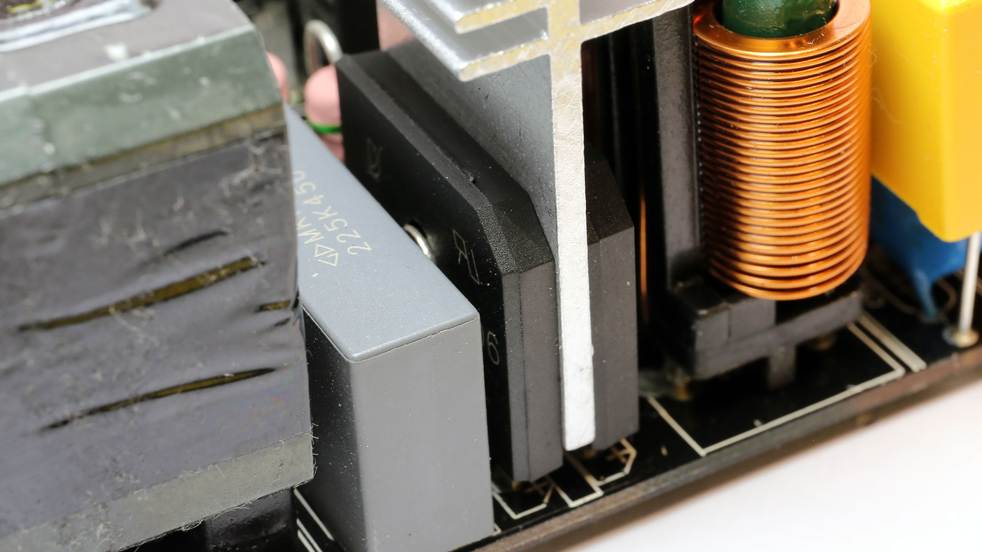
The APFC converter uses two NCE Power FETs and a single JF boost diode. The bulk cap is by Chemi-Con. A bulk cap with a 420 V rating would have been ideal.
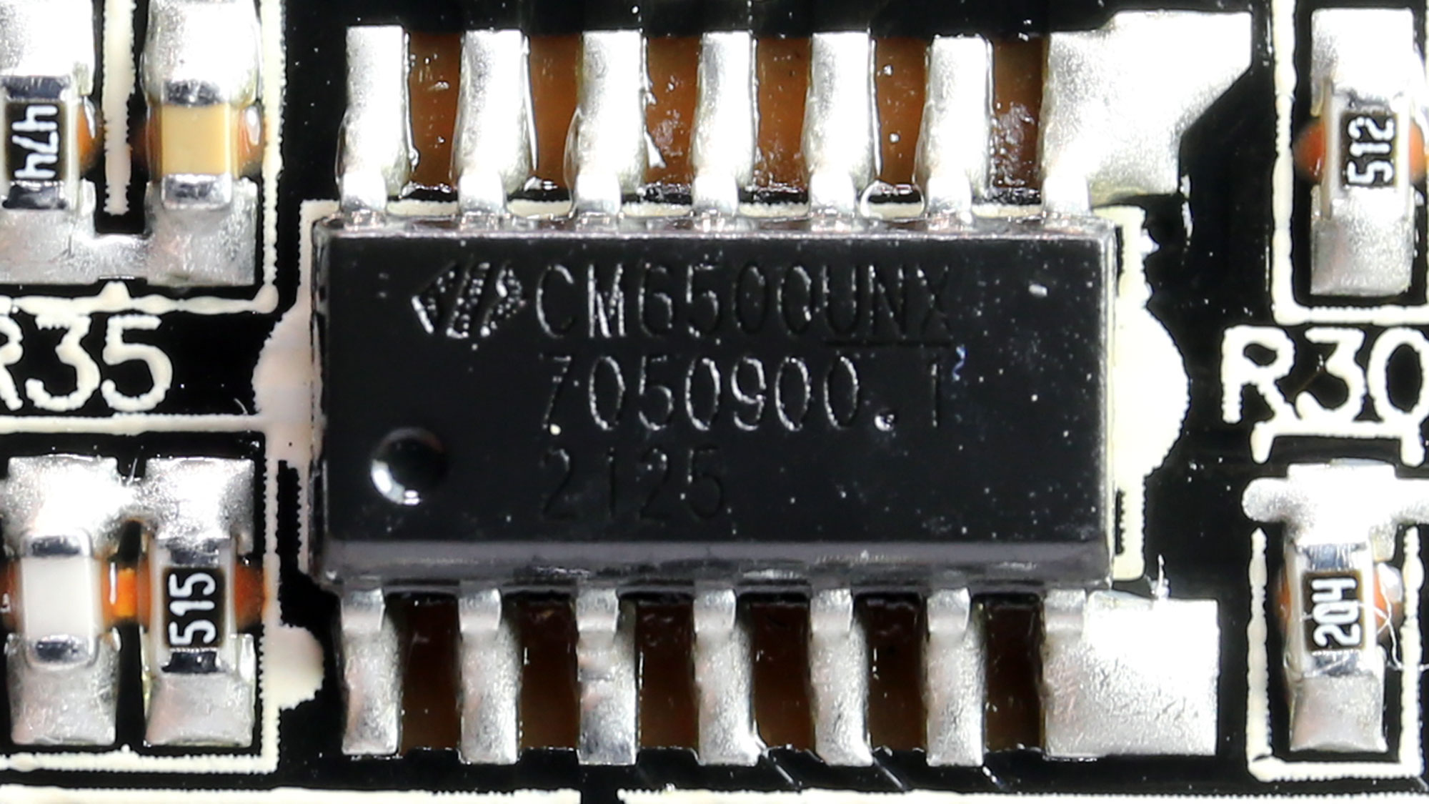
The APFC controller is a Champion CM6500UNX.

The two NCE Power primary switching FETs are installed in a half-bridge topology.

The resonant controller is a Champion CM6901T6X.

The main transformer is next to the parts for the LLC resonant controller.

Like the 850 W unit, the FETs regulating the +12 V rail are hidden by a pair of heat sinks attached to the main ones through screws. I didn't want to remove them because I might need the PSU for future measurements. As such, I couldn't identify the 12 V FETs at top of the PCB.
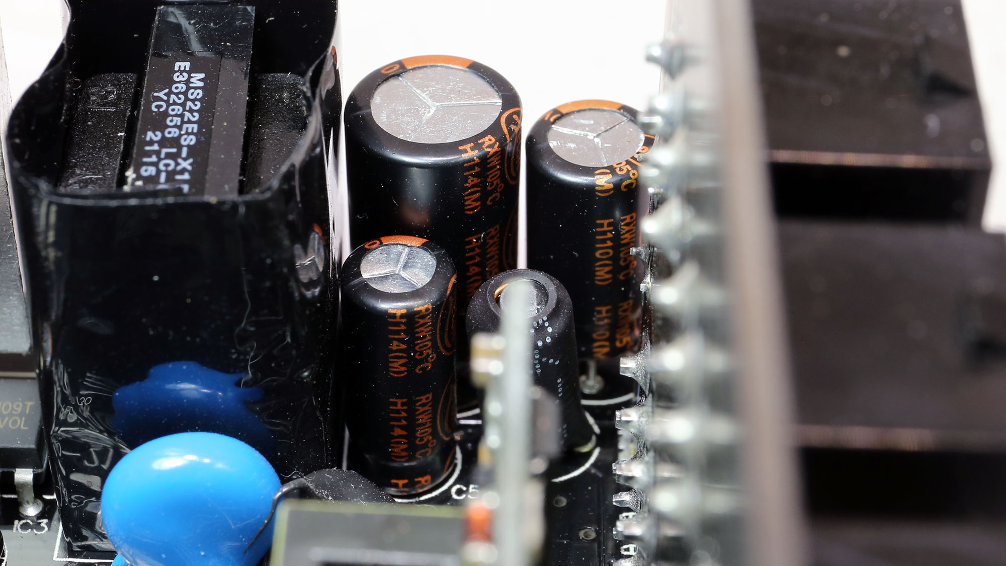


The electrolytic caps on the secondary side are by Lelon. There are also eight polymer caps from the same brand.
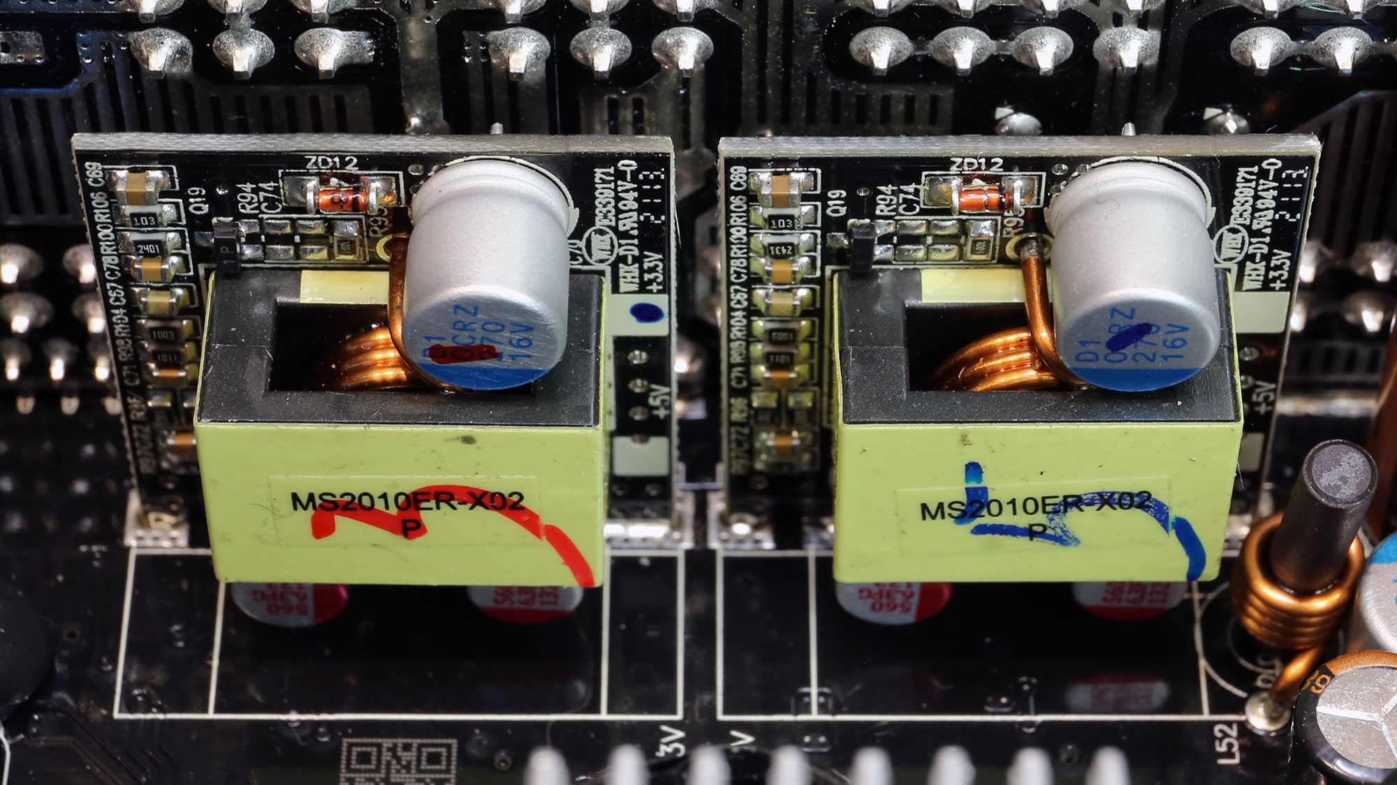
Two DC-DC converters generate the minor rails.
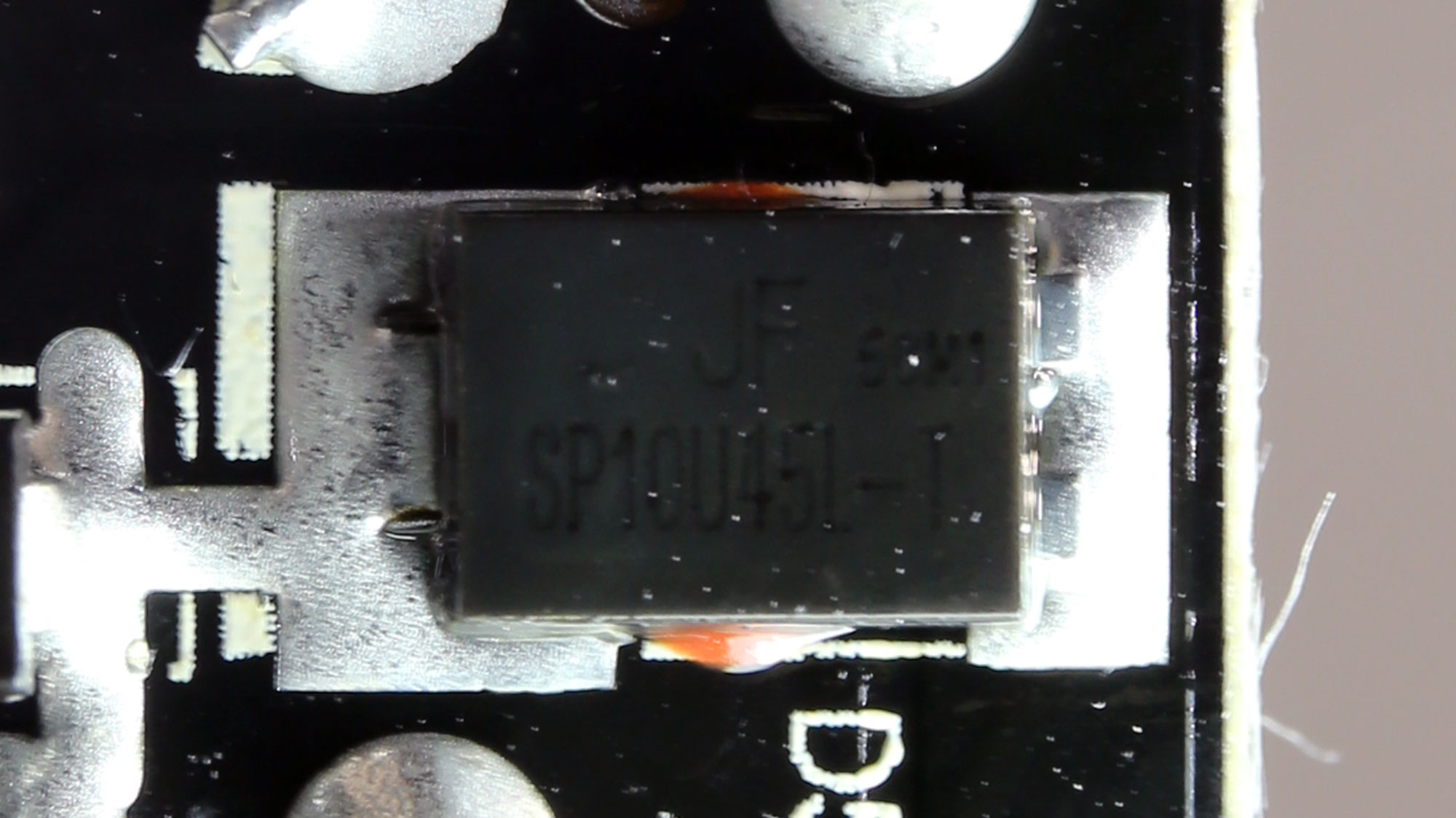

The standby PWM controller is a PR8109T IC, and the 5VSB secondary rectifier is an SP10U45L SBR.

The supervisor controller is a Weltrend WT7502R.


Two polymer and six electrolytic caps on the modular PCB further reduce ripple.
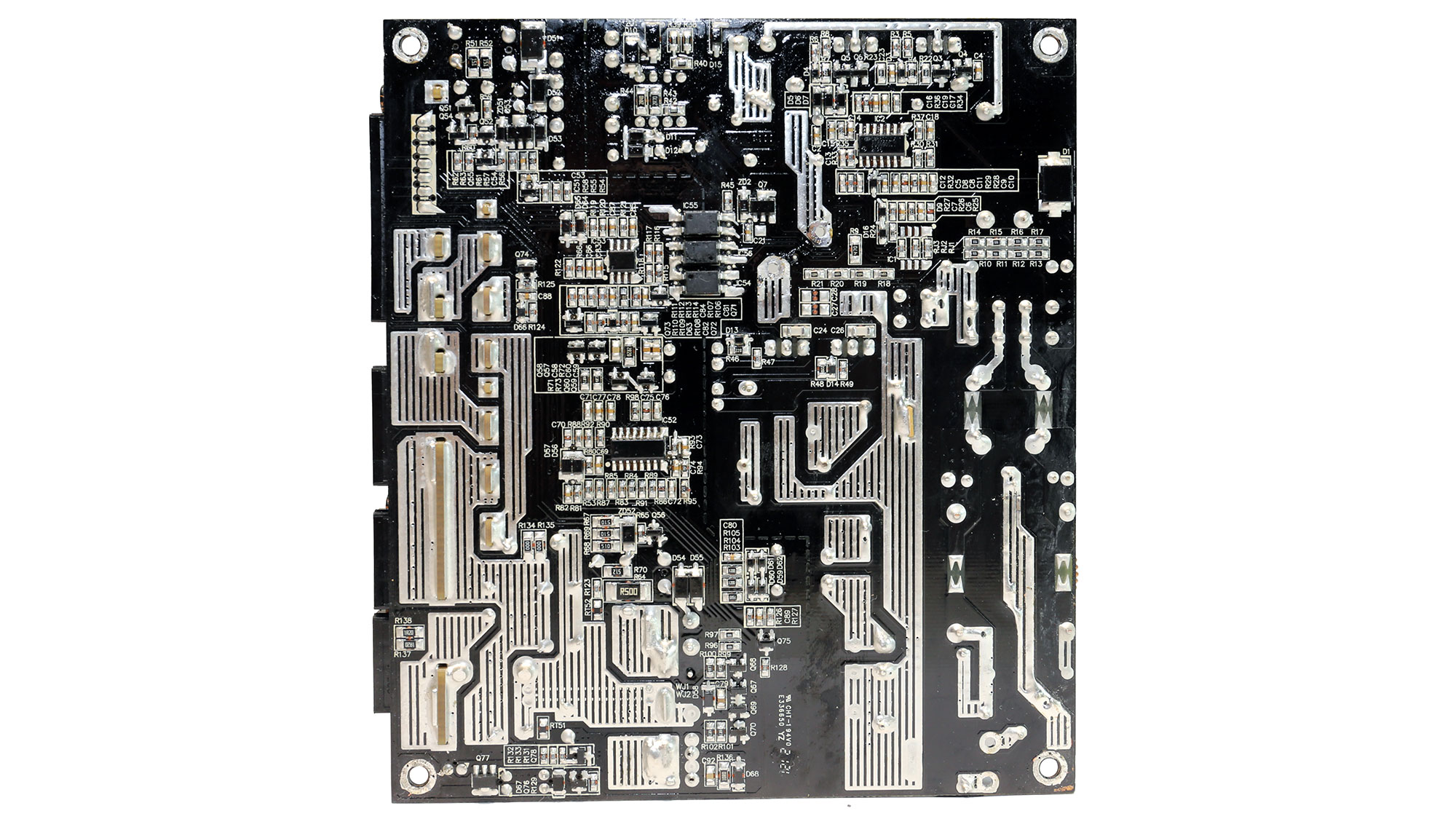


Soldering quality is great!


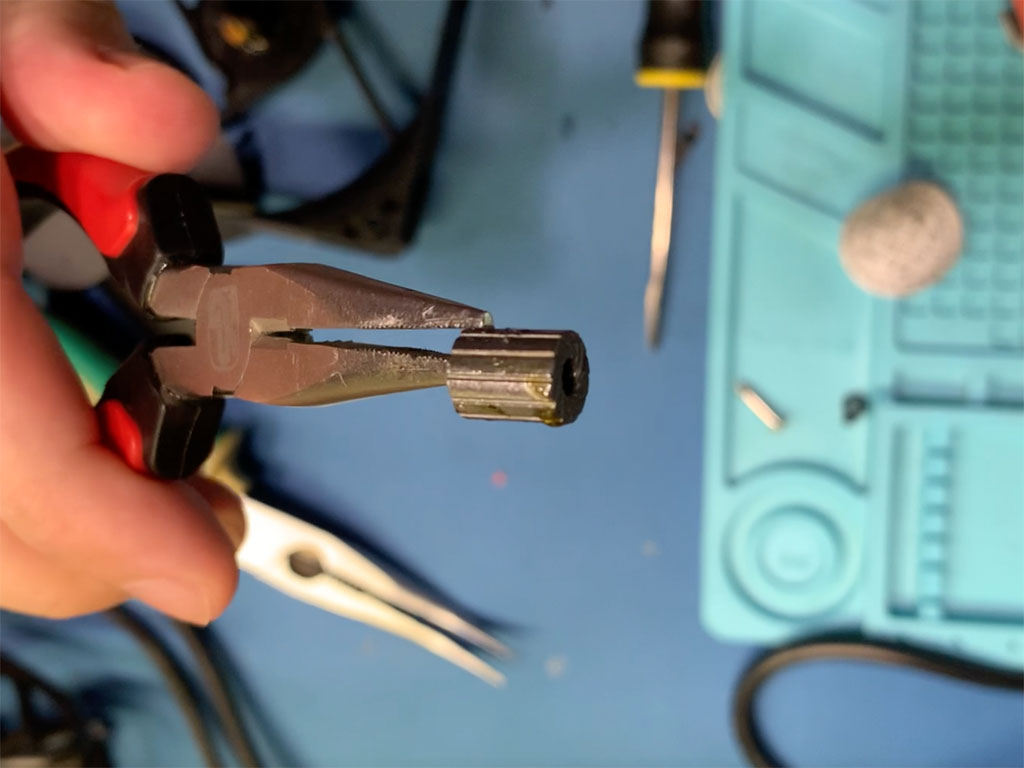
This is the same fan as in the lower-capacity PG-M units. It is supposed to have a high-quality hydraulic bearing. However, having taken it apart in the P750GM review, it uses a plain rifle bearing instead. Still, a rifle bearing is far better than a plain sleeve one.
Test Setup

Our Patreon Silver Supporters can read articles in single-page format.
Apr 26th, 2024 10:33 EDT
change timezone
Latest GPU Drivers
New Forum Posts
- Meta Horizon OS (21)
- Old high quality PSU, or semi-old mid-quality PSU? (3)
- Secure boot already open help (8)
- What are you playing? (20540)
- Horizontal black lines popping up on my screen? (13)
- Alphacool CORE 1 CPU block - bulging with danger of splitting? (26)
- What's your latest tech purchase? (20351)
- The Official Linux/Unix Desktop Screenshots Megathread (698)
- Which new games will you be buying? (321)
- GoDeal24 Windows 11 Pro 32-bit! (3)
Popular Reviews
- HYTE THICC Q60 240 mm AIO Review
- MOONDROP x Crinacle DUSK In-Ear Monitors Review - The Last 5%
- Alienware Pro Wireless Gaming Keyboard Review
- Upcoming Hardware Launches 2023 (Updated Feb 2024)
- Thermalright Phantom Spirit 120 EVO Review
- ASUS Radeon RX 7900 GRE TUF OC Review
- FiiO K19 Desktop DAC/Headphone Amplifier Review
- RTX 4090 & 53 Games: Ryzen 7 5800X vs Ryzen 7 5800X3D Review
- NVIDIA RTX 4090: 450 W vs 600 W 12VHPWR - Is there any notable performance difference?
- RTX 4090 & 53 Games: Core i9-13900K vs Ryzen 7 5800X3D Review
Controversial News Posts
- Windows 11 Now Officially Adware as Microsoft Embeds Ads in the Start Menu (123)
- Sony PlayStation 5 Pro Specifications Confirmed, Console Arrives Before Holidays (117)
- NVIDIA Points Intel Raptor Lake CPU Users to Get Help from Intel Amid System Instability Issues (106)
- AMD "Strix Halo" Zen 5 Mobile Processor Pictured: Chiplet-based, Uses 256-bit LPDDR5X (101)
- US Government Wants Nuclear Plants to Offload AI Data Center Expansion (98)
- AMD's RDNA 4 GPUs Could Stick with 18 Gbps GDDR6 Memory (90)
- Developers of Outpost Infinity Siege Recommend Underclocking i9-13900K and i9-14900K for Stability on Machines with RTX 4090 (85)
- Windows 10 Security Updates to Cost $61 After 2025, $427 by 2028 (84)