 3
3
i-Rocks K70E Capacitive Keyboard Review
Driver »Disassembly


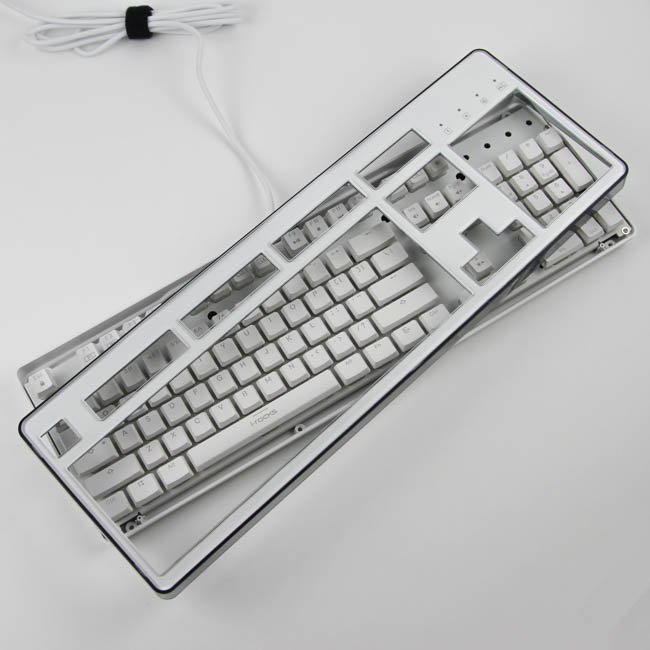
Disassembly of the i-Rocks K70E capacitive keyboard is complicated in that there are multiple stages involved, and towards the end, things can go wrong easily. I do not encourage this unless you absolutely must. The first stage involves the removal of the top plate cover from the rest of the keyboard, which is done by removing eight Phillips head screws on the back, which includes one under the warranty void sticker.


The top plate piece is actually comprised of three separate pieces - the transparent acrylic top cover, paper skin, and smoked acrylic side piece. Note the notches where the two acrylic pieces connect, and this is also how you can remove the top cover to access and change out the paper skin without removing any screws. Once done, insert the top plate at one end to then bend it inward at the other end so it slides into place. If it feels as though it won't go in despite a lot of force, attempt the whole thing again lest you break it instead.


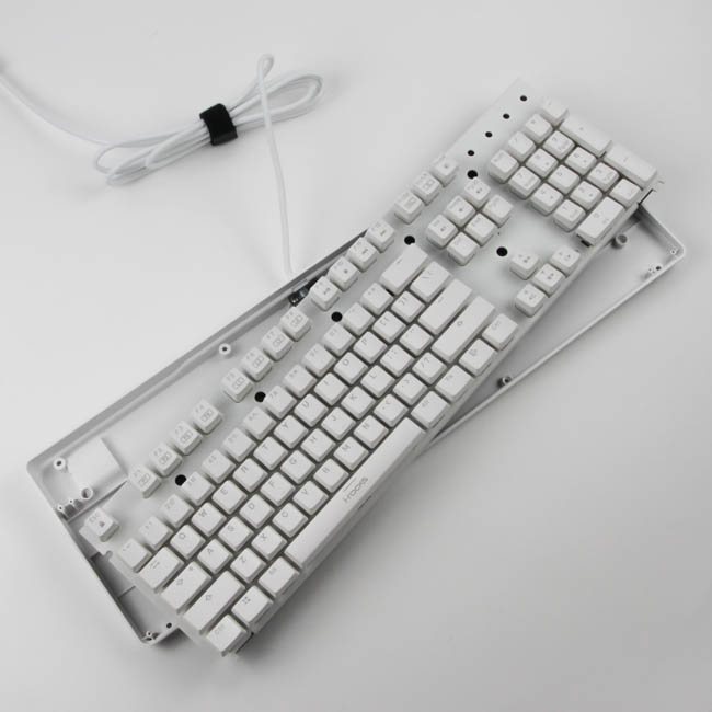
The next stage is the removal of the bottom plastic case panel from the rest of the keyboard, and this is where i-Rocks got extra sneaky by only having two screws hold it in place (with the others having been removed before). Both of these screws are under the certification label on the back, so there are telltale signs going to the left which show that the unit was opened up. Once done, the case comes loose, but is still connected to the PCB.


Carefully turn everything around to expose the internal USB connector, and dislodge the cable from it to free the plastic case. We can see here that there is cable management integrated into the case's internals as well. On to the other piece now, and it's different from that of most other keyboards. We do not really see anything of note here on the exposed side of the PCB aside from two screws and what appears to be a ribbon cable.


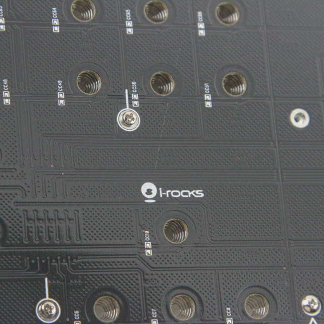
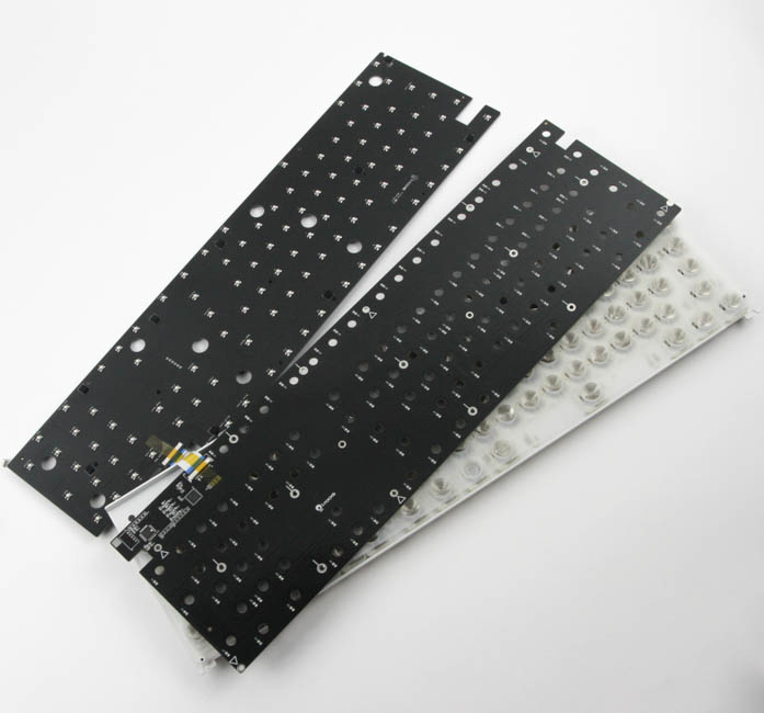
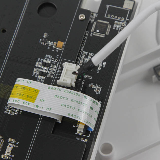
Removing those two screws shows that the i-Rocks K70E has a dual-PCB system - one for the lighting and the other for the switches. This is neat in that you are now no longer limited to a specific LED size, but this can be more expensive as well, and the LEDs are also further away from the top of the keyboard, which effectively reduces brightness. The ribbon cable connecting the two has a strong adhesive tape on this sample, but you do not need to separate the two to access the internals further. Indeed, a closer look at the second PCB reveals yet more screws which are of different lengths and staggered at different heights on the PCB, so it is quite easy to lose track of which screw goes where. The telltale conical spring associated with the capacitive switch design can also be seen through the holes in the PCB here.


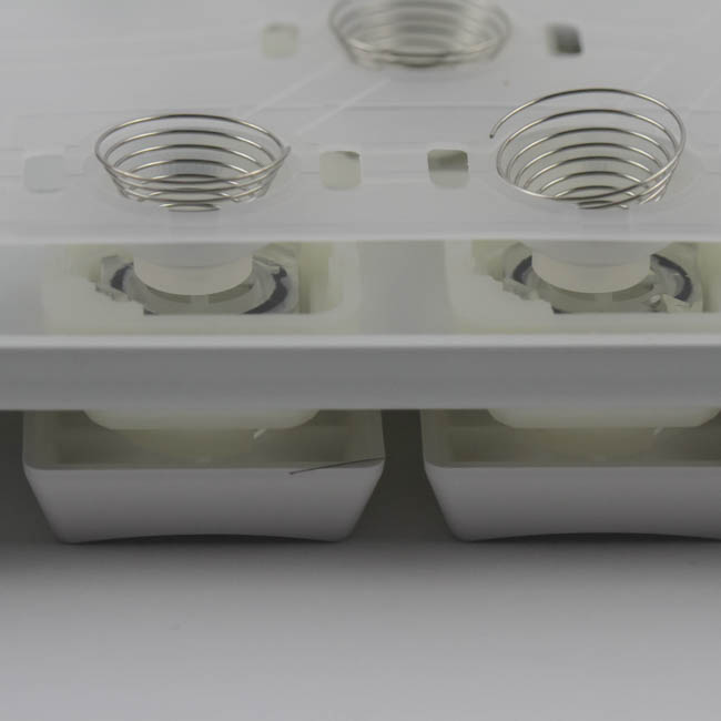

Having removed the final set of screws, both PCBs can be taken off, which reveals the underside of where the conical springs make contact. The remaining pieces are the springs, rubber dome membrane sheet, and the rest of the switches (housing, plunger/stem/slider, and O-ring), which are all kept in place on the stainless steel plate used to provide structural integrity as well. It is very easy to lose a spring here, so be careful and keep count of them all. Alongside the images is a cutout illustration of how the capacitive switch used here is formed.
For those who saw the rubber dome mentioned above and are curious about how, if at all, these switches are different from the standard membrane switches used, let me say right away that they are quite different. Membrane switches as we know them are contact switches with the keystroke actuation occurring when the conductor on the underside of the dome touches the contact point on the PCB. Thus, they need to be bottomed-out for actuation to occur, and the tactile feedback comes from the resistance of the dome itself. With capacitive switches, the PCB needs to have a mechanism to measure the capacitance as you actuate the switches. This comes via one or more capacitor pads per switch that are in turn covered with dielectrics. This change in capacitance with switch travel can be translated to the keystroke, so the switch maker can choose a specific actuation travel point/points depending on how precise the detection mechanism is. The spring also contributes to the tactile feedback here, in addition to the rubber dome, and the feeling of typing on such switches is similar and yet different to membrane switches regardless of whether you bottom out or not.


Knowing now that the capacitance detection is quite important, we see that the i-Rocks K70E keyboard handles this using a Azoteq IQS550 projected capacitive controller capable of handling touchscreens and trackpads, and keyboards are well within the limitations of this controller as well. The actual keyboard functionality, including the pre-programmed functions by i-Rocks, are handled by a MEGAWIN MG84F5161-T 80C51 CPU based off the Harvard microarchitecture using CISC (complex instruction set computer). It has 64 KB of onboard flash memory with up to 4 MB of additional RAM, and an integrated 8-16-bit PWM timer and controller that can potentially handle the lighting onboard since I did not see dedicated LED drivers elsewhere. Solder quality is exceptional on both PCBs, which are also both multi-layered for those who care.
Before we move on, be advised that disassembly will void the warranty and that TechPowerUp is not liable for any damages incurred if you decided to go ahead and do so anyway.
May 17th, 2024 08:40 EDT
change timezone
Latest GPU Drivers
New Forum Posts
- 20 Years? (37)
- What's your latest tech purchase? (20542)
- Finally a lithium starting battery (3)
- Hi, my GPU suddenly dropped in performance 2 days ago and i have been trying to fix it since then, my GPU clock is capped at 300 MHz (5)
- LOL ASUS says this is $200 in repair, Steve from gamers Nexus smokes ASUS, Steam Deck til I die boys!!!! (104)
- EULA in Games (28)
- Sapphire Rx 6700 XT (2)
- Would you pay more for hardware with AI capabilities? (28)
- Ryzen Owners Zen Garden (7371)
- What are you playing? (20658)
Popular Reviews
- Homeworld 3 Performance Benchmark Review - 35 GPUs Tested
- Enermax REVOLUTION D.F. X 1200 W Review
- Lofree Edge Ultra-Low Profile Wireless Mechanical Keyboard Review
- Silverstone Shark Force 120 mm Fan Review
- Upcoming Hardware Launches 2023 (Updated Feb 2024)
- AMD Ryzen 7 7800X3D Review - The Best Gaming CPU
- ZMF Caldera Closed Planar Magnetic Headphones Review
- Corsair MP700 Pro SE 4 TB Review
- Horizon Forbidden West Performance Benchmark Review - 30 GPUs Tested
- ASUS Radeon RX 7900 GRE TUF OC Review
Controversial News Posts
- Intel Statement on Stability Issues: "Motherboard Makers to Blame" (268)
- AMD to Redesign Ray Tracing Hardware on RDNA 4 (227)
- Windows 11 Now Officially Adware as Microsoft Embeds Ads in the Start Menu (172)
- NVIDIA to Only Launch the Flagship GeForce RTX 5090 in 2024, Rest of the Series in 2025 (154)
- AMD Hits Highest-Ever x86 CPU Market Share in Q1 2024 Across Desktop and Server (138)
- AMD RDNA 5 a "Clean Sheet" Graphics Architecture, RDNA 4 Merely Corrects a Bug Over RDNA 3 (130)
- AMD's RDNA 4 GPUs Could Stick with 18 Gbps GDDR6 Memory (114)
- AMD Ryzen 9 7900X3D Now at a Mouth-watering $329 (104)