 7
Lian Li Edge Platinum V2 1350 W Review
Test Methodology »Internals
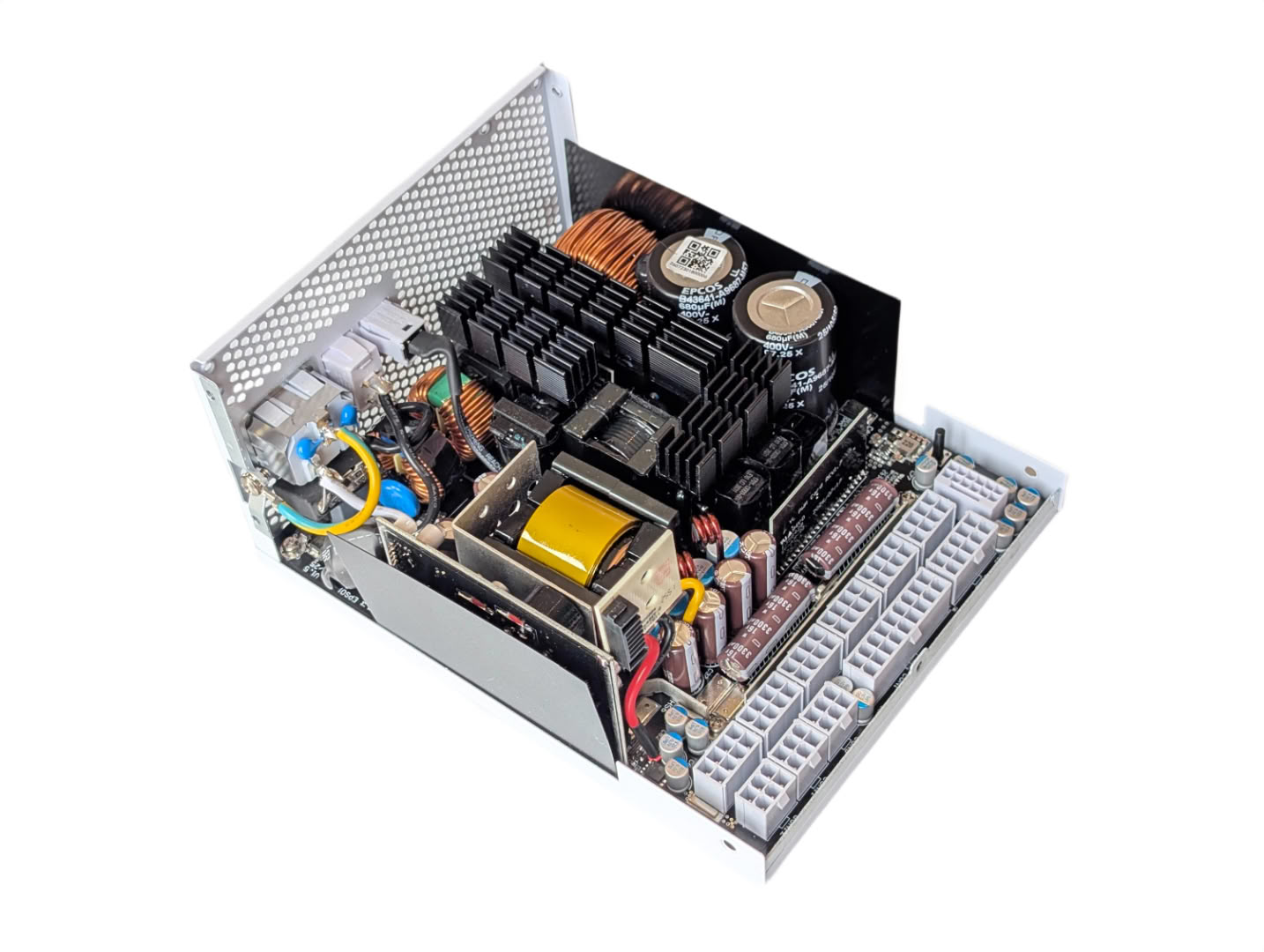
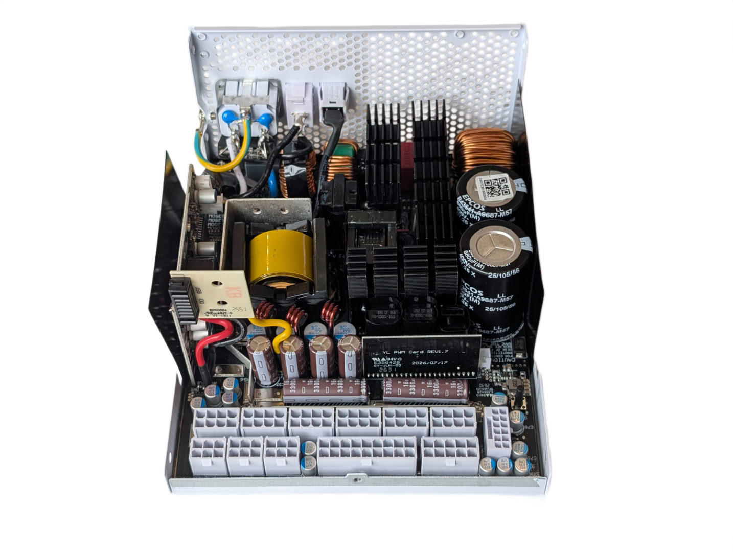
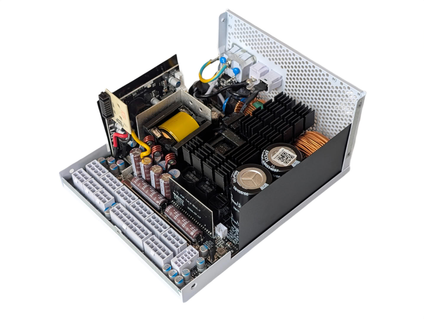
Taking the top and front panel off reveals tightly packed internals, with plenty of heatsinks and capacitors.
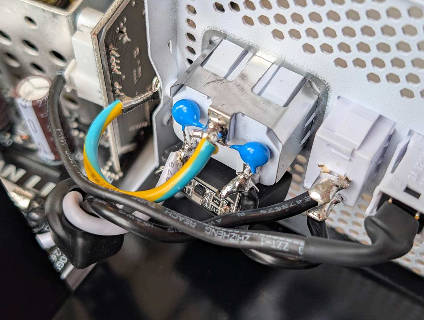
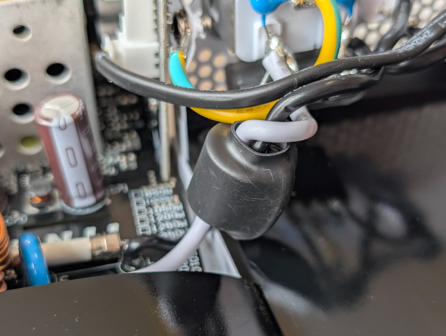
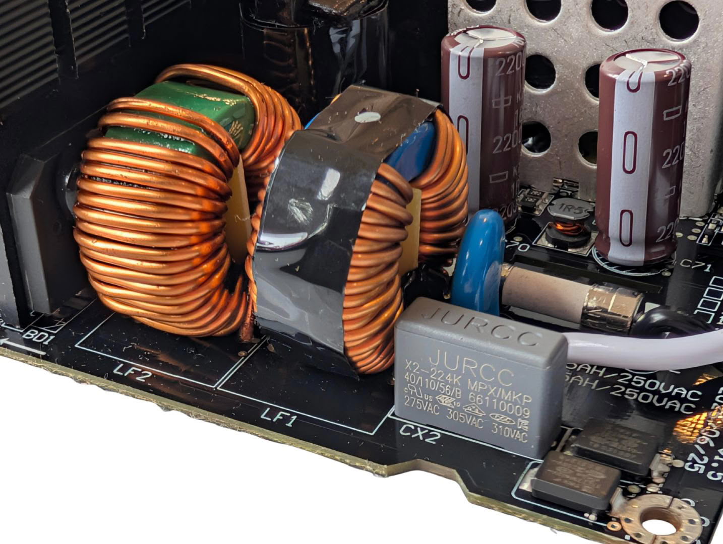
Directly soldered to the power terminals are a pair of Y caps, and an X cap with discharge circuitry. On the way to the main board is a ferrite core on the mains cables, and once we reach the board there is a second X cap, MOV, fuse and a pair of CM chokes. The only thing we sometimes see from other high-end units is a grounded copper sheet around all the mains filter components, which isn't present here.
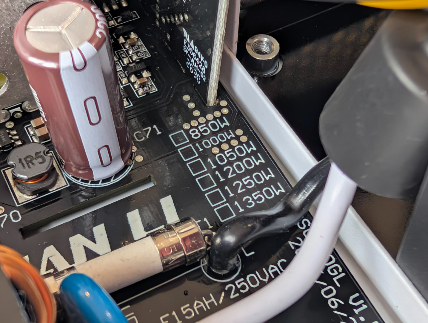
From the silkscreen we can see that this PCB is shared across a wide range of power levels, from 850 W to 1350 W.
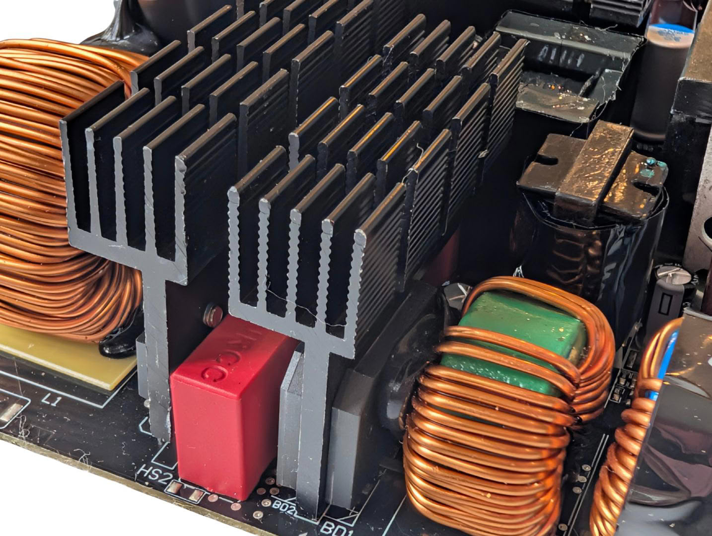
The pair of full bridge rectifiers are on their own heatsink which is a good size with plenty of fins. This alone helps improve efficiency since the hotter these run, the more internal resistance they have.
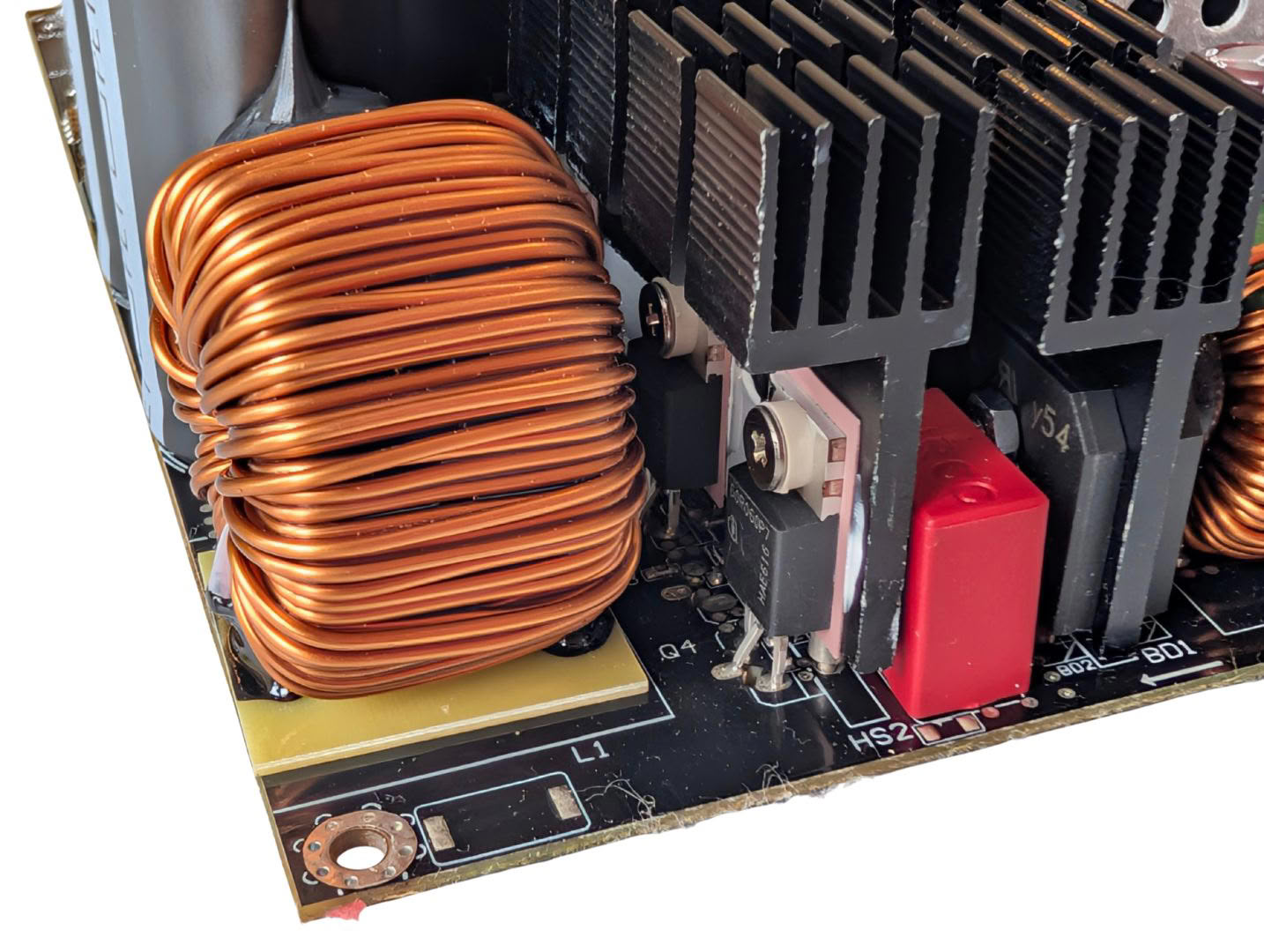
The APFC components are also on their own heatsink which has plenty of surface area.
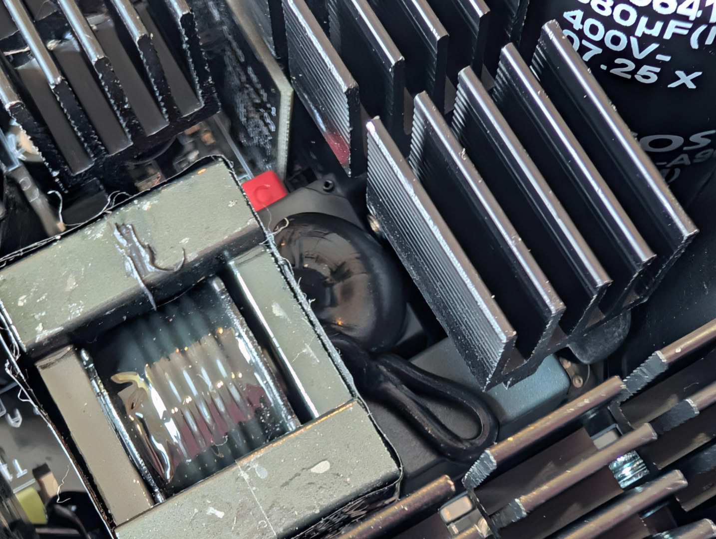
Inrush suppression components consisting of this thermistor and relay are squeezed in between heatsinks and transformers.
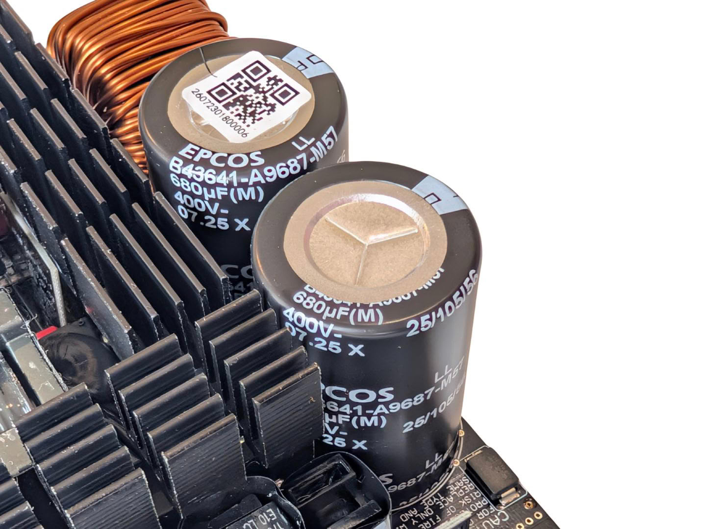
A pair of high quality 400 V German EPCOS caps make up the bulk storage, rated for 680 uF each and totaling 1360 uF at 105°C. This offers good headroom, as modern APFC controllers work well with much less bulk capacitance even at this power level.
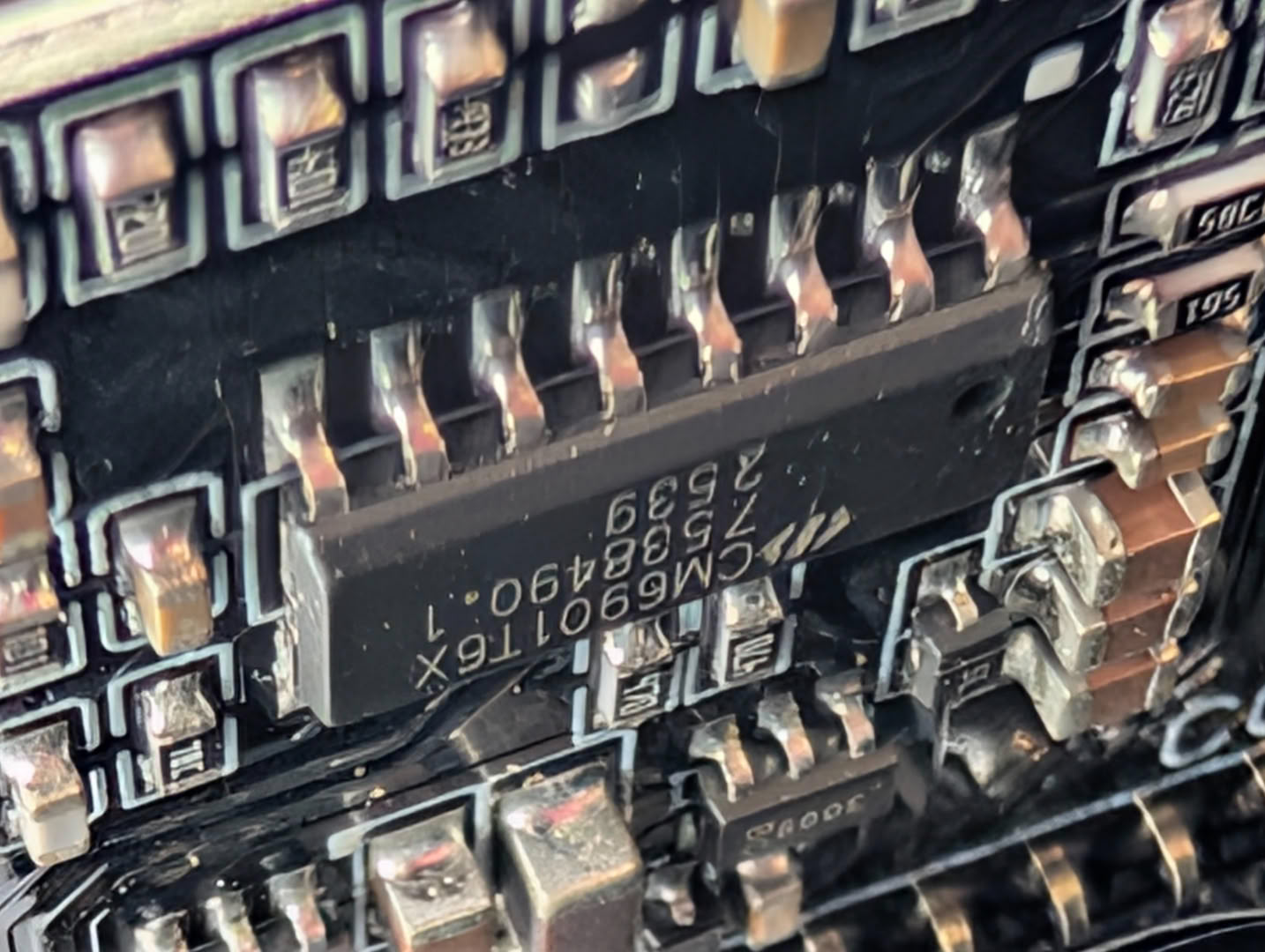
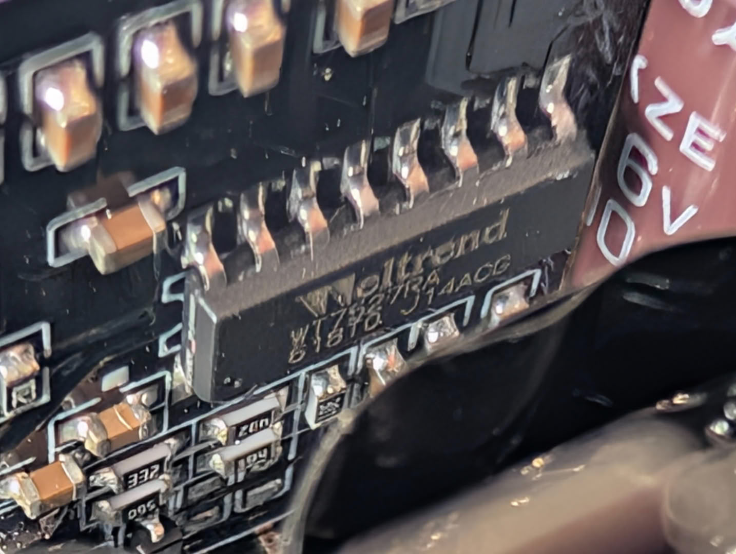
A dedicated PWM card houses the main PWM controller, the CM6901, which drives both the main switchers and the 12 V MOSFETs very efficiently, switching modes depending on current draw. The supply as a whole is managed and protected by the Weltrend WT7527, also mounted to the PWM card.
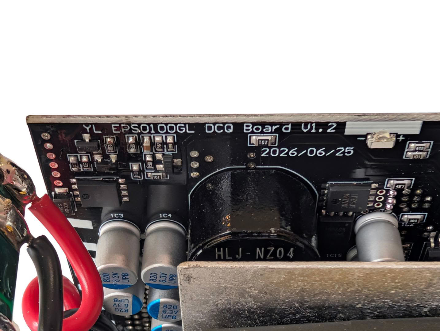
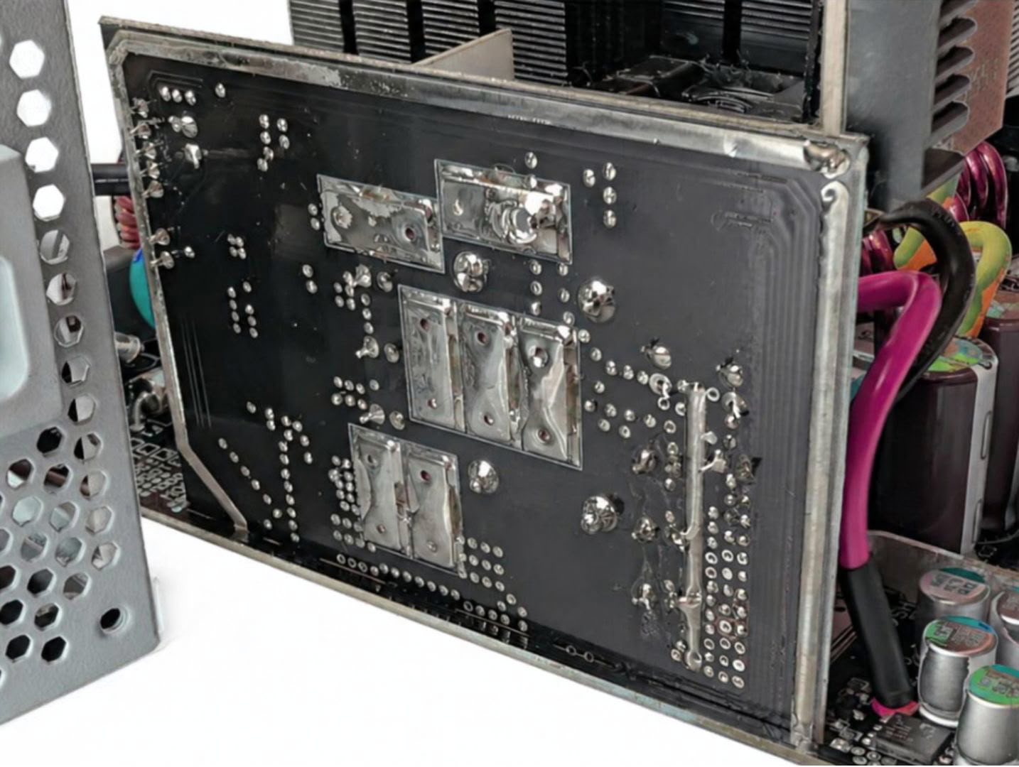
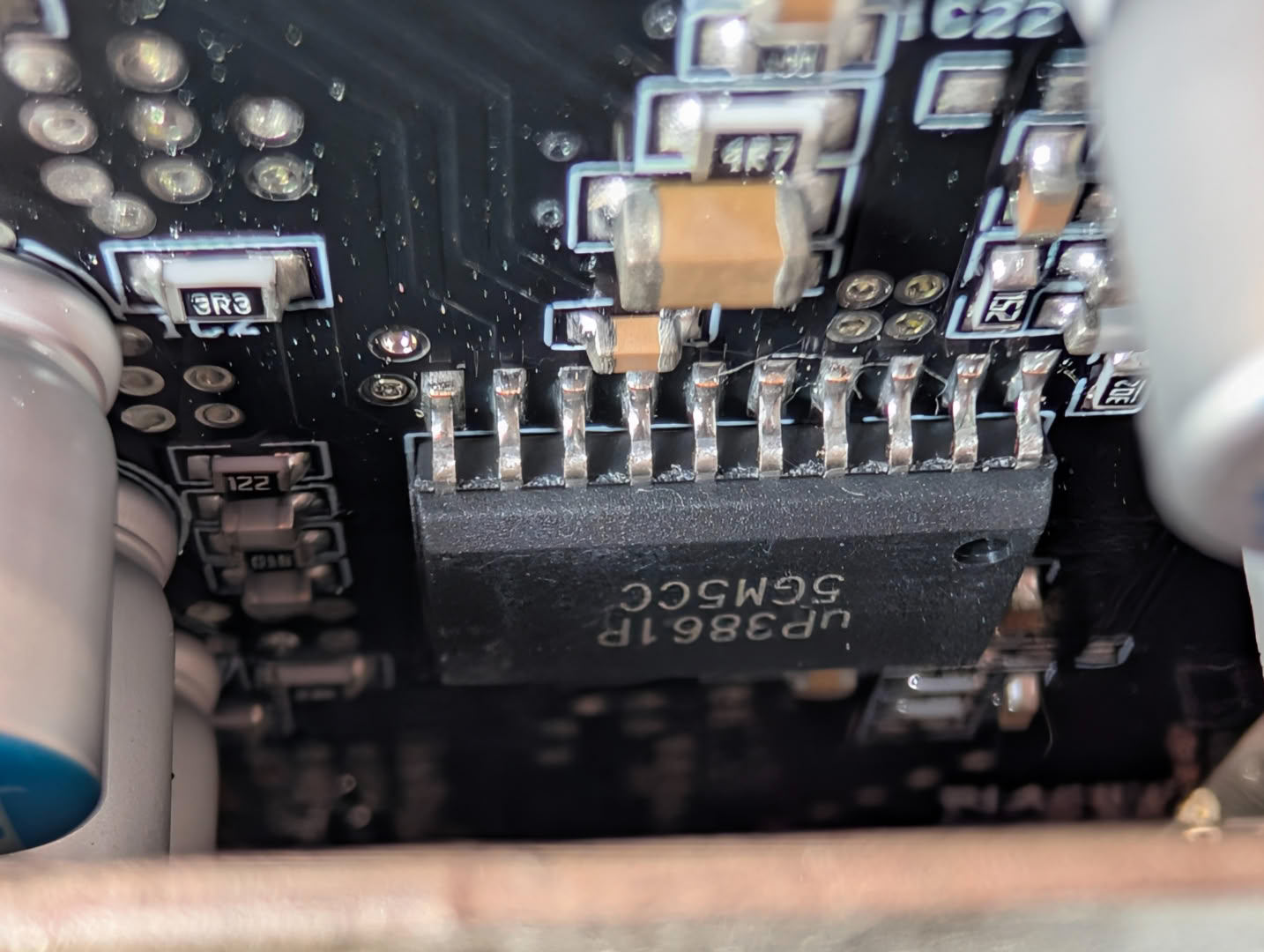
DC-DC conversion for the minor rails is handled by this upright PCB. The MOSFETs and inductors for both 3.3 V and 5 V are mounted here, driven by the UP3861 IC. There are some extra metal strips on the rear for added thermal mass and to lower trace resistance. The PCB itself acts as the heatsink for these MOSFETs.
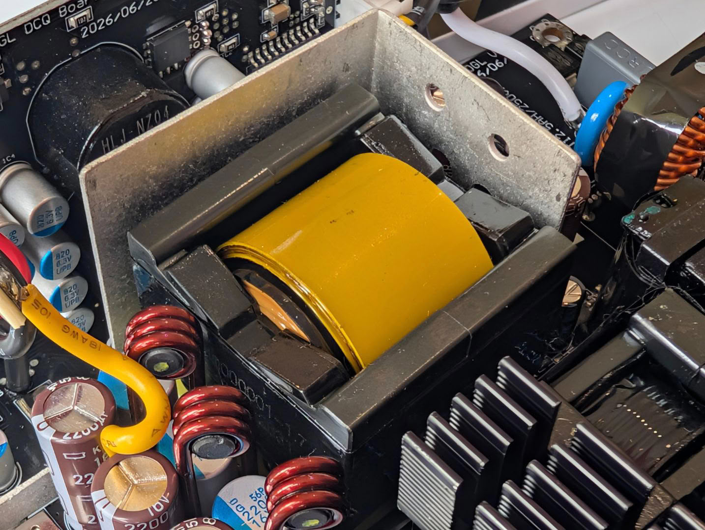
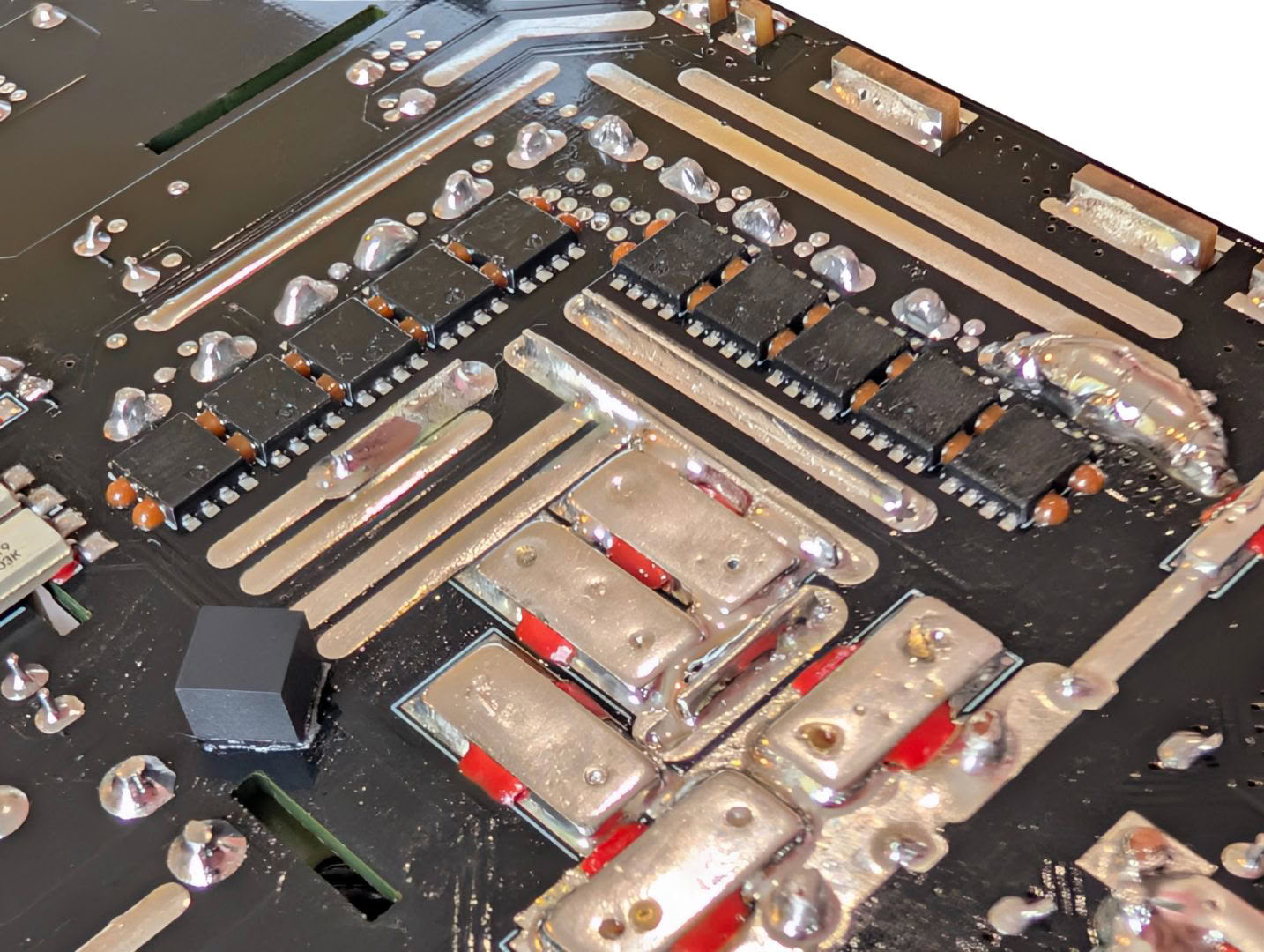
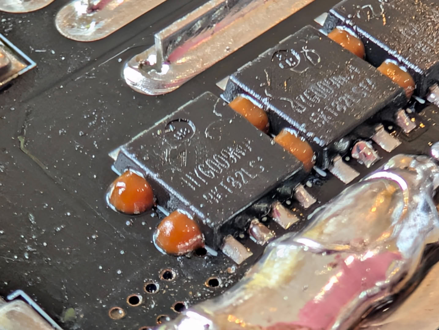
Creating the main 12 V rail are eight HYG009N04LS1C2 MOSFETs mounted to the underside of the PCB. These are 200 A monsters with an RDS(on) of just 0.75mΩ, crucial for minimal heat generation and high efficiency. There is plenty of mass around them for current transfer and to wick away heat, in addition to a large metal plate bent around the main transformer to bring what little heat is generated up into the airflow from the fan.
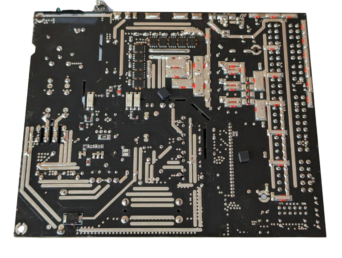
There are minimal components on the underside of the PCB, mainly the 12 V MOSFETs, a few resistors and SMD capacitors, and optocouplers.
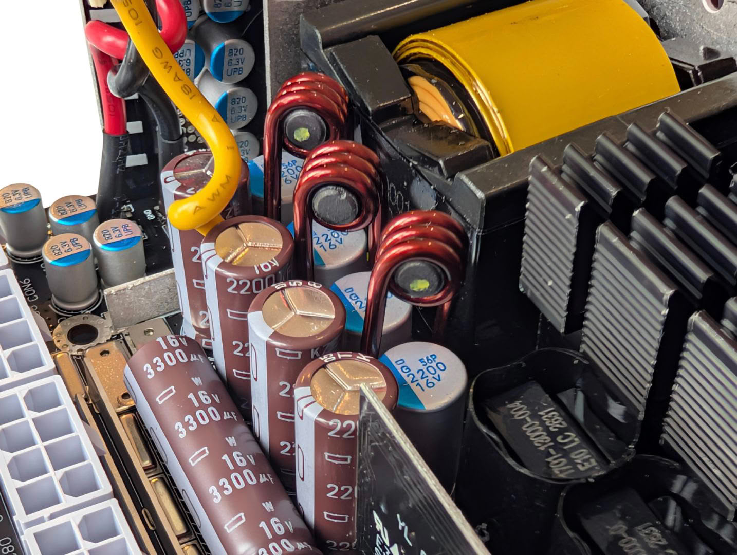
There has been plenty of care taken to reduce ripple and noise on the 12 V rail, with a decent quantity of quality capacitors, and these little filter inductors raised above the board that otherwise wouldn't fit.
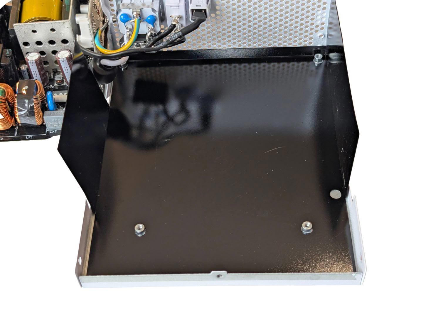
Some PSUs use the main case to wick heat away from the 12 V MOSFETs by using thermal pads between the back of the PCB and the case. Lian Li have opted against this, suggesting the thermal mass and fan are adequate.
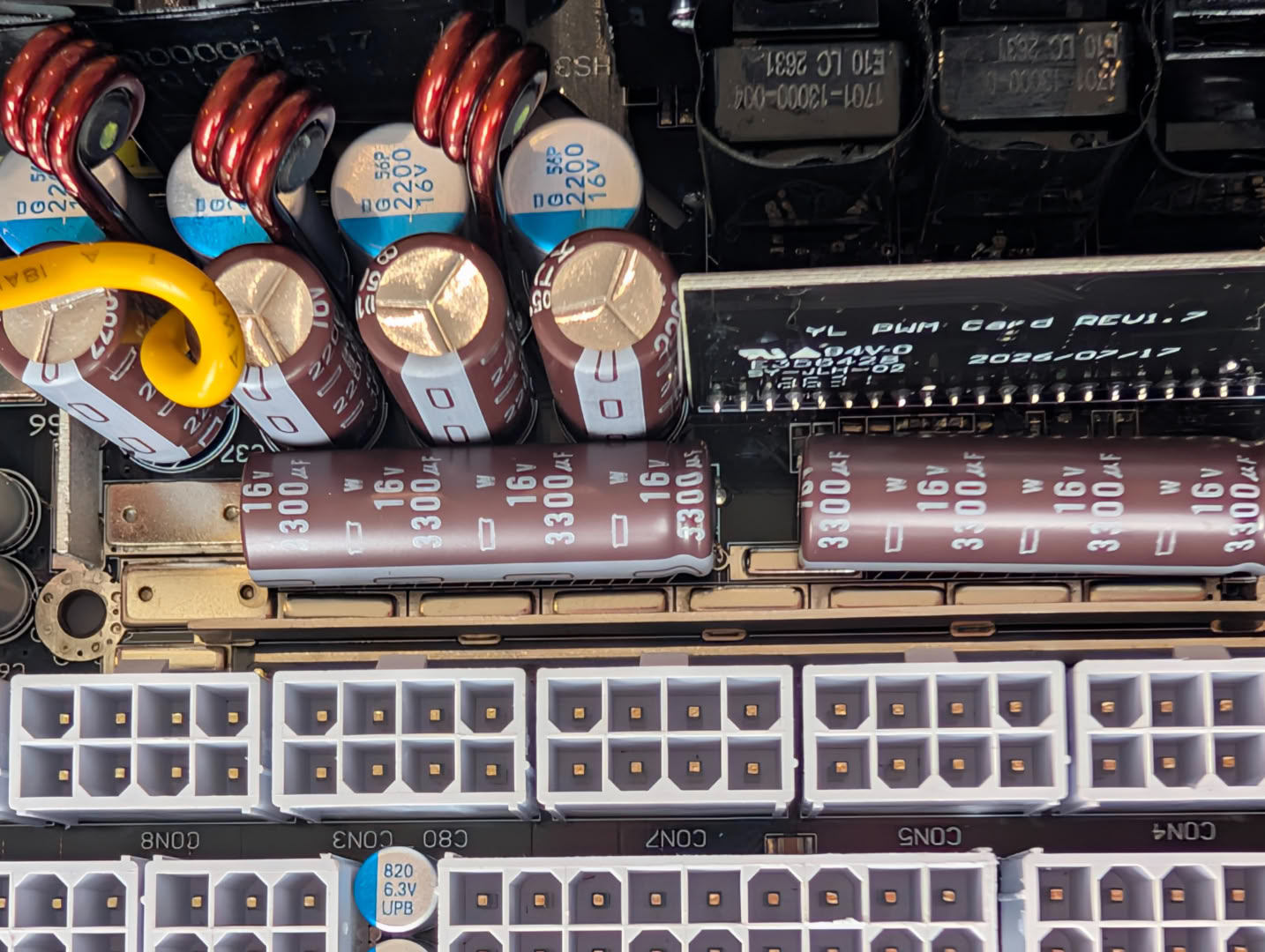
Small metal bars or strips are soldered on the traces for the main 12 V rail to lower the overall trace resistance, reducing losses and improving efficiency.
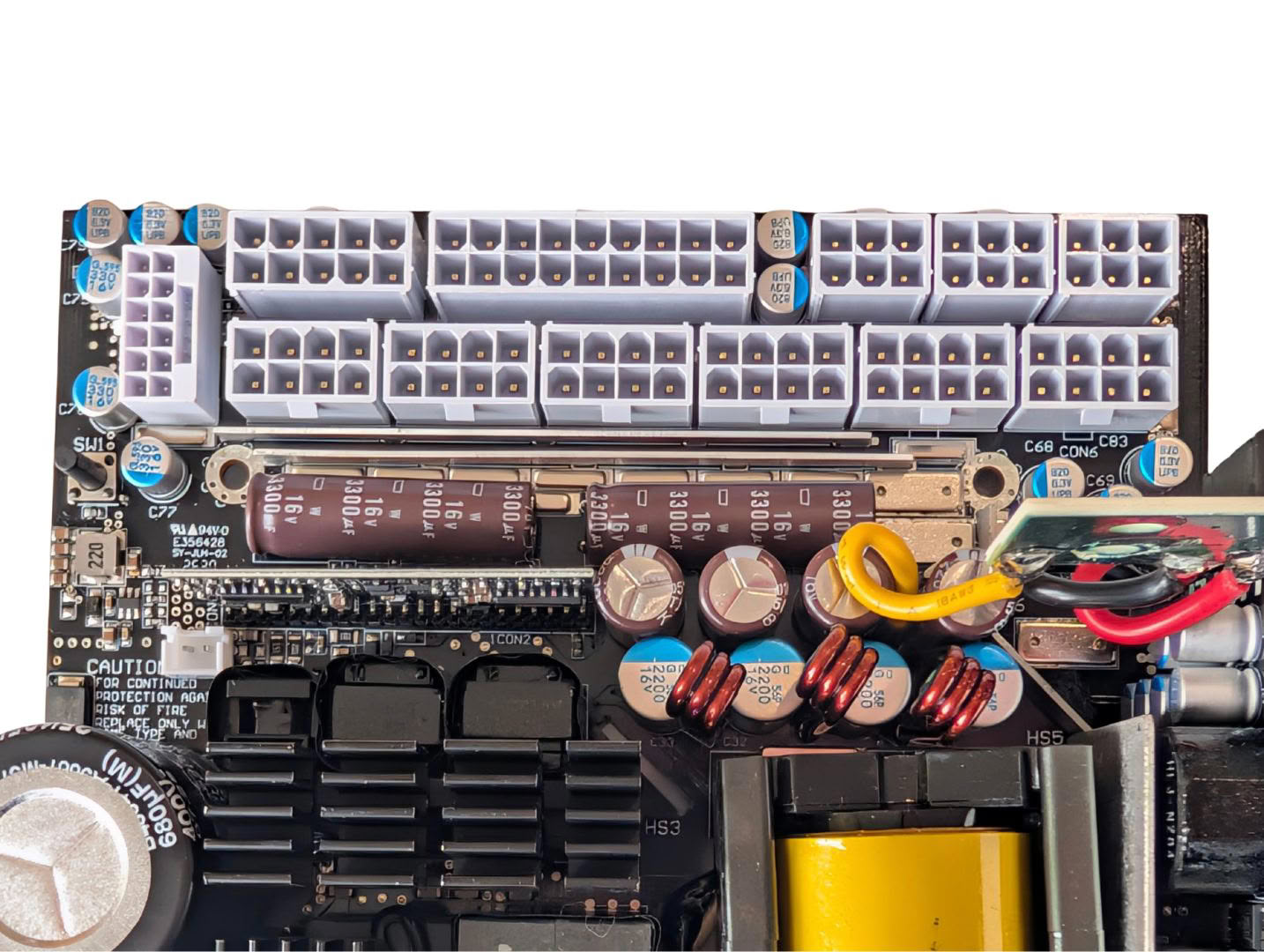
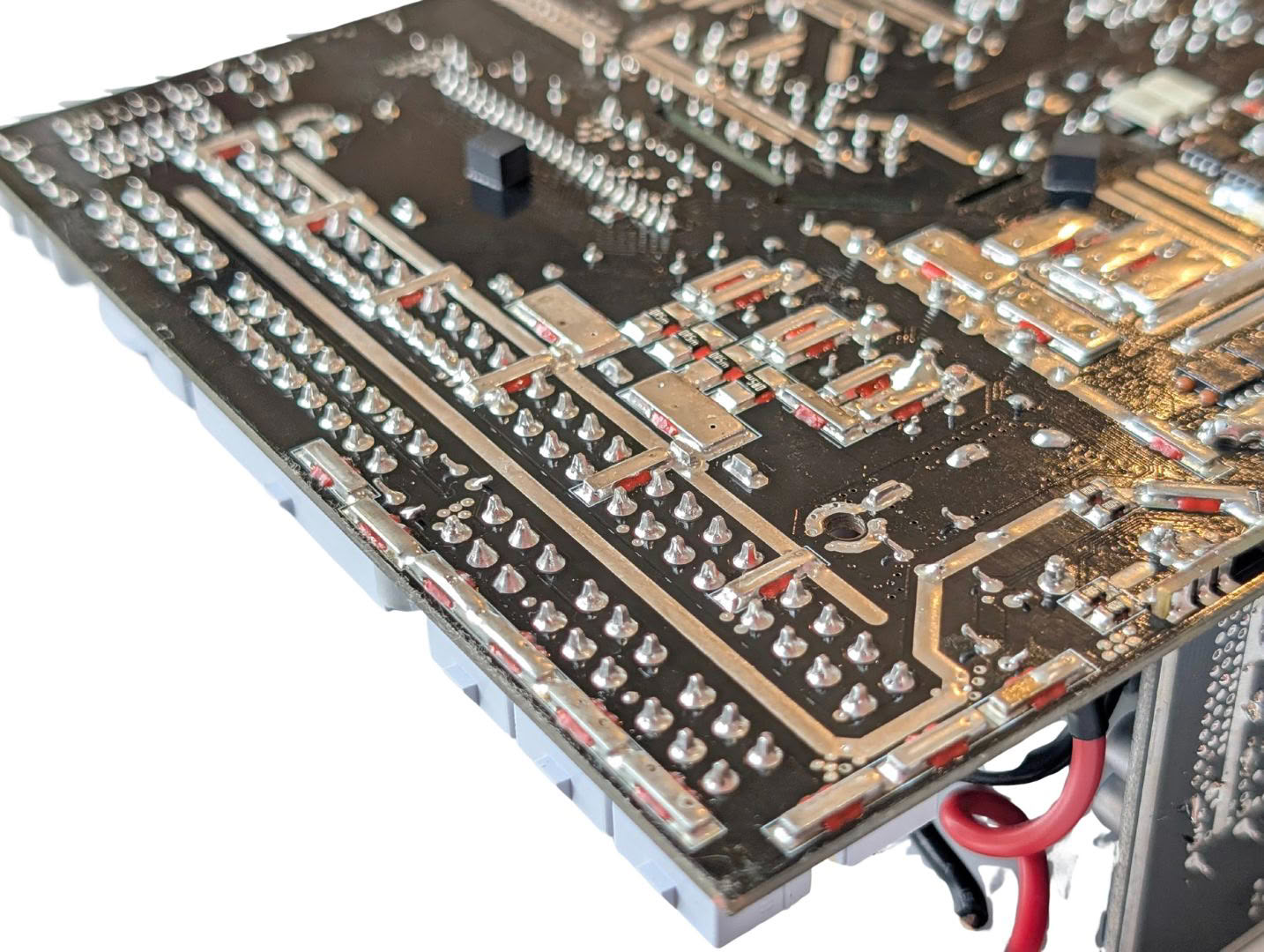
An unintentional benefit of this form factor is that there are no physical connections between the main board and the connectors, since here they are on the same PCB. There is very little space among the connectors, but any space available has been filled with further smoothing caps right by the connectors themselves.
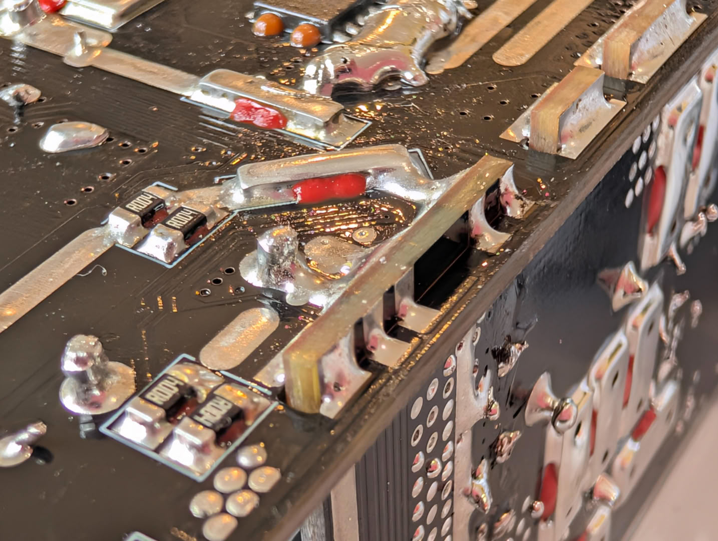
As you will know from previous reviews, I am not a fan of this connection style for upright daughter boards. There is too much leverage on the small delicate 90 degree solder connection, which is prone to cracks when the upright board moves or vibrates. Generally a PC isn't an environment that moves or vibrates much, but with time and certain circumstances this could be an unnecessary failure point.
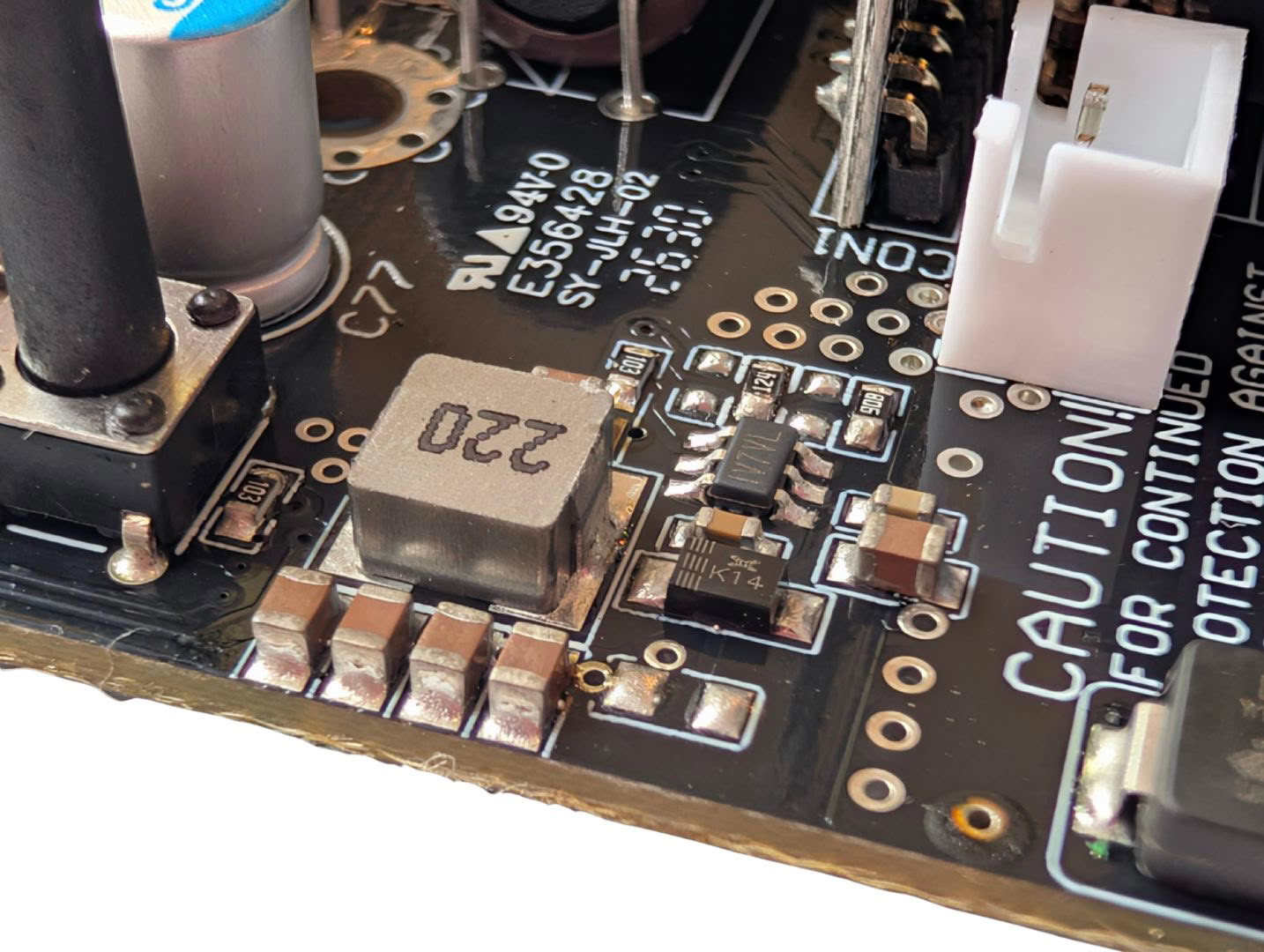
The soldering quality throughout the board is excellent with good consistency and finish. The SMD components are secured with adhesive before the soldering stage during manufacturing, which prevents component shifting and forming undesirable connections.
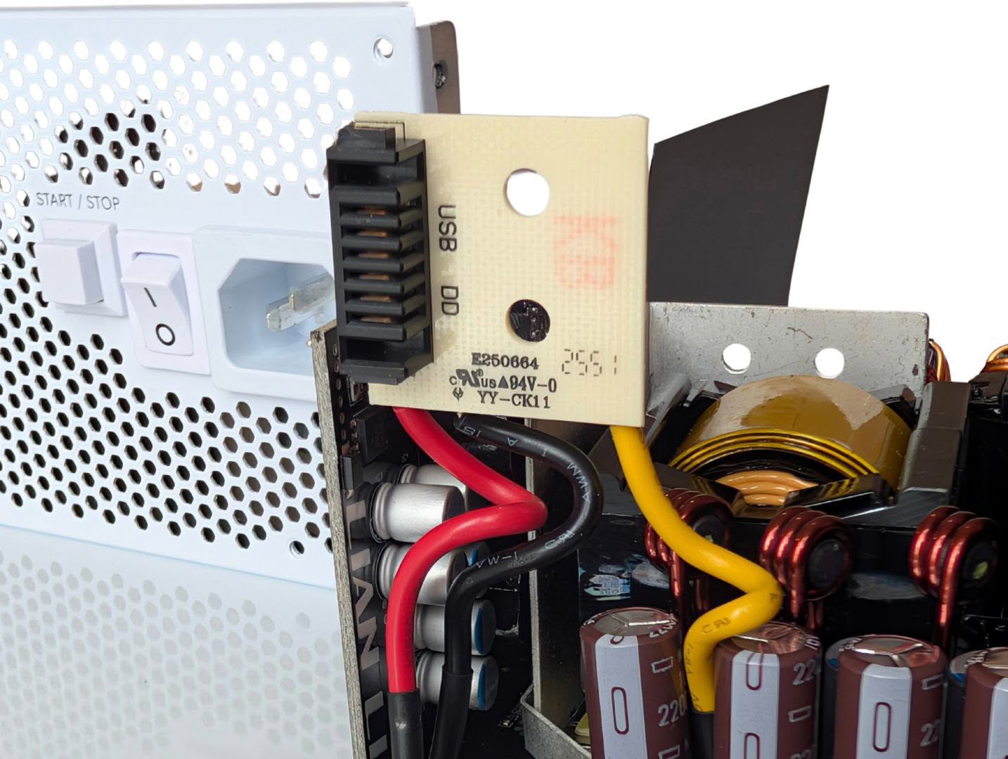
There is a little connector board for the Hub ADV, which takes 12 V and 5 V rails and a ground from the main board.
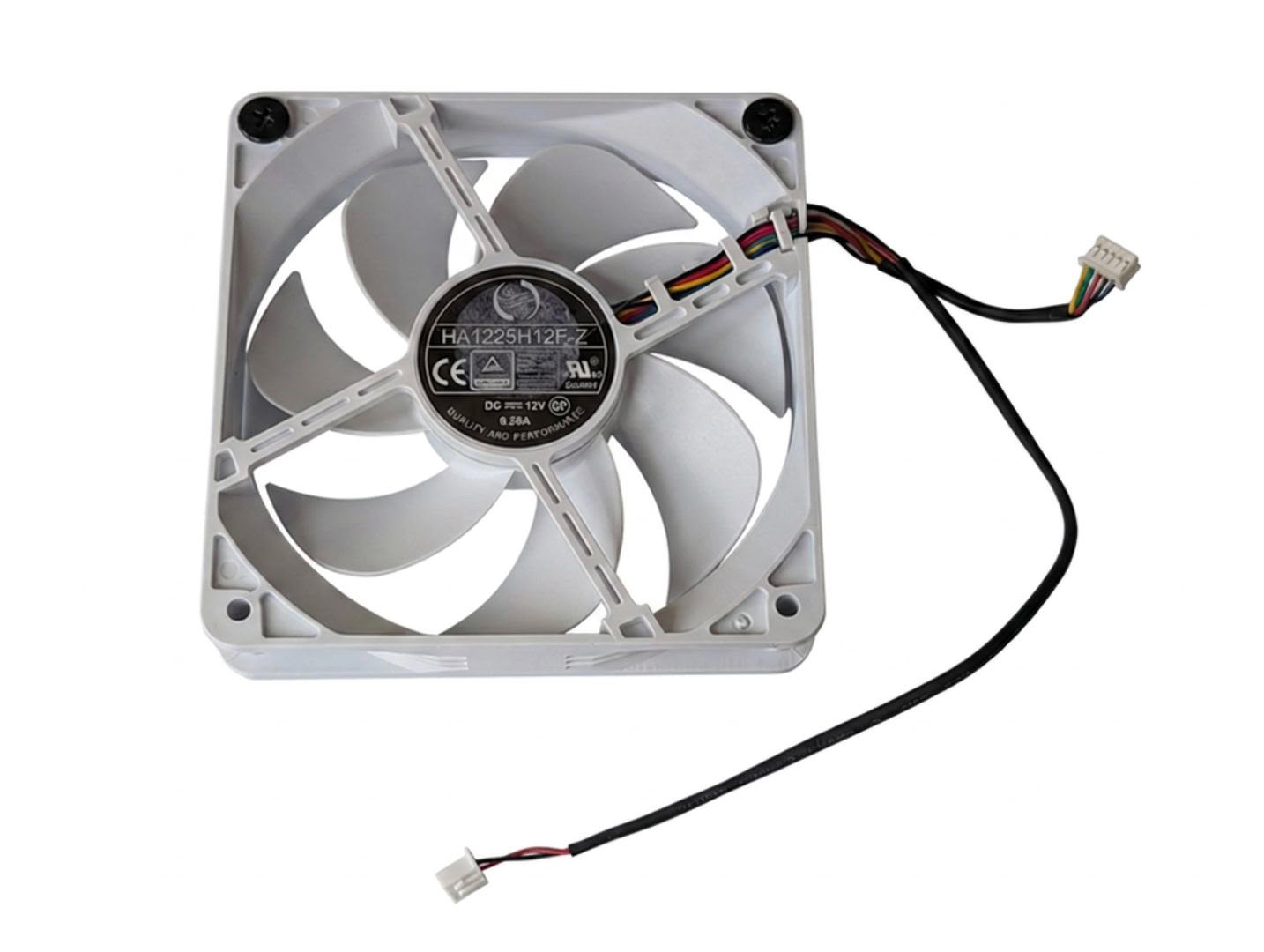
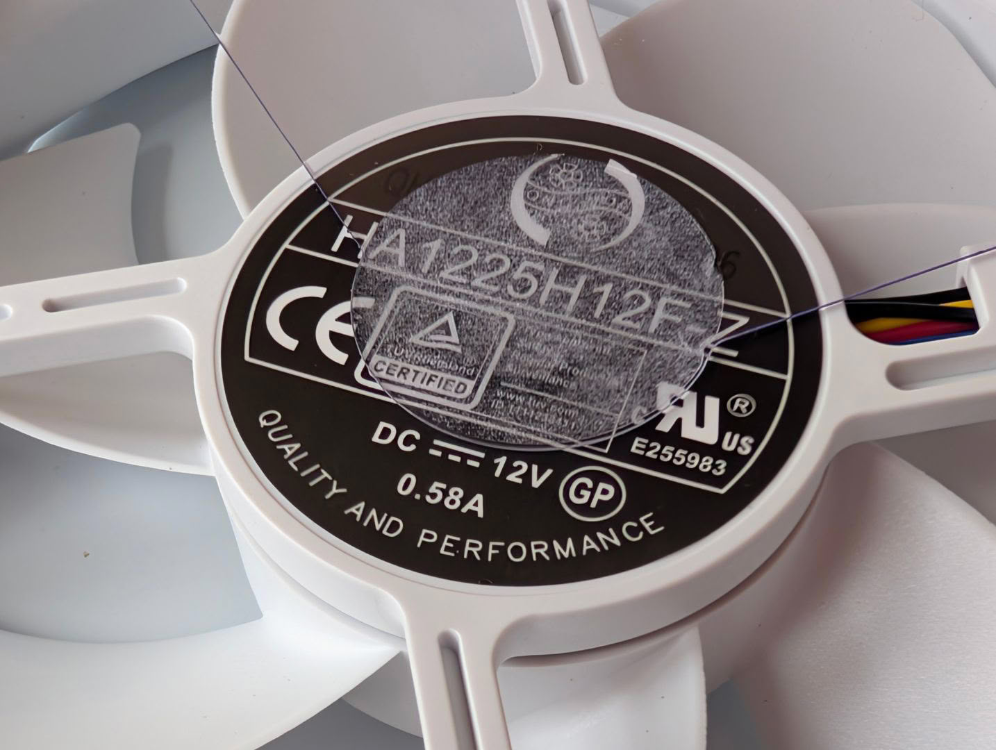
The selected fan is a well-known model by Hong Hua, often selected for mid- to high-end PSU models from a range of OEMs. It has a True Hydro Dynamic bearing and can spin up to 2200 RPM, although many brands will impose a lower max limit in the fan curve. The blade design is specifically tailored for static pressure, which is crucial for high density power supplies. This model has proven to be a reliable workhorse.
Nov 16th, 2026 04:14 CST
change timezone
Latest GPU Drivers
New Forum Posts
- What can the FX 8320 do today? Here is the answer. (61)
- GPU Temperatures Rise Very Quickly in FurMark – Is This Normal? (13)
- I pushed the limits with an AMD Ryzen 7 5700G Apu (1)
- a note from zachary85's son (10)
- Is a C6K 2026 or a400m worth coming from a samsung bu8000 ? (0)
- [Community Benchmark] MrH OpenCL Benchmark 2.0e (Windows Only – CPU & GPU) (4)
- Your PC ATM (36443)
- Asus Rog Maximus Z890 Extreme. (Various questions). (27)
- GIGABYTE - H55N-USB3 ITX Upgrade experience (0)
- Advice for my PC upgrade (0)
Popular Reviews
- ASUS ROG Strix B850-I Gaming Wi-Fi7 W Review
- Corsair HX1000i Shift Crystal Review
- AMD Zen 6 Technical Deep Dive
- Upcoming Hardware Launches 2027 (Updated Nov 2026)
- Montech King 95 3D PRO Review
- NZXT C1200 Platinum Review
- Phantom Blade Zero Performance Benchmark Review - 35 GPUs Tested
- AMD Ryzen 7 9800X3D Review - The Best Gaming Processor
- NZXT H7 RGB+ Review
- NZXT H5 Review
TPU on YouTube
Controversial News Posts
- NVIDIA Co-Founder and CEO Jensen Huang Officially Resigns (430)
- Open Letter Asking NVIDIA to Reinstate Jensen Huang Passes 115,000 Signatures (184)
- OpenAI CEO Argues Home PCs Waste the World's Limited DRAM Supply (152)
- NVIDIA Launches Investigation Into Jensen Huang's Relationship With Suspected Chinese Spy (136)
- Intel "Raptor Lake Next" 16-Core and 20-Core CPUs Surface (130)
- Legendary Game Studio BioWare Shuts Down Following EA Layoffs (104)
- Dell CEO Says the Memory Shortage Will Get Worse in 2027 (95)
- NVIDIA GeForce RTX 50-Series Scheduled for up to $500 Price Hike This Week (89)