 2
Ocypus lota P1000 Review
Value & Conclusion »Result Summary
| Full-Range Load Testing (230 V) | |||||||||
|---|---|---|---|---|---|---|---|---|---|
| All-rail Load | 12 V | 5 V | 3.3 V | Power (DC/AC) | Efficiency | Fan Speed | Noise Level | Power Factor | |
| 0 % | 0 A | 4.00 A | 6.06 A | 0.00 W | 0.00 % | Fan Stop | 0.11 | ||
| 12.11 V | 5.04 V | 3.37 V | 3.00 W | ||||||
| 5 % | 0.83 A | 4.00 A | 6.06 A | 50.00 W | 80.65 % | Fan Stop | 0.72 | ||
| 12.22 V | 5.14 V | 3.55 V | 62.00 W | ||||||
| 10 % | 5.00 A | 4.00 A | 6.06 A | 100.00 W | 83.58 % | Fan Stop | 0.87 | ||
| 12.22 V | 5.14 V | 3.55 V | 119.65 W | ||||||
| 20 % | 13.33 A | 4.00 A | 6.06 A | 200.00 W | 89.09 % | Fan Stop | 0.94 | ||
| 12.19 V | 5.14 V | 3.55 V | 224.50 W | ||||||
| 30 % | 21.67 A | 4.00 A | 6.06 A | 300.00 W | 90.73 % | Fan Stop | 0.96 | ||
| 12.16 V | 5.14 V | 3.55 V | 330.65 W | ||||||
| 40 % | 30.00 A | 4.00 A | 6.06 A | 400.00 W | 90.98 % | Fan Stop | 0.96 | ||
| 12.13 V | 5.14 V | 3.55 V | 439.65 W | ||||||
| 50 % | 38.33 A | 4.00 A | 6.06 A | 500.00 W | 90.73 % | 591 RPM | 26.1 dBA | 0.97 | |
| 12.11 V | 5.14 V | 3.55 V | 551.10 W | ||||||
| 60 % | 46.67 A | 4.00 A | 6.06 A | 600.00 W | 90.62 % | 591 RPM | 26.1 dBA | 0.97 | |
| 12.08 V | 5.14 V | 3.54 V | 662.10 W | ||||||
| 70 % | 55.00 A | 4.00 A | 6.06 A | 700.00 W | 90.46 % | 591 RPM | 26.1 dBA | 0.97 | |
| 12.06 V | 5.14 V | 3.54 V | 773.85 W | ||||||
| 80 % | 63.33 A | 4.00 A | 6.06 A | 800.00 W | 90.28 % | 1182 RPM | 28.9 dBA | 0.98 | |
| 12.05 V | 5.14 V | 3.54 V | 886.10 W | ||||||
| 90 % | 71.67 A | 4.00 A | 6.06 A | 900.00 W | 89.91 % | 1182 RPM | 28.9 dBA | 0.98 | |
| 12.03 V | 5.14 V | 3.54 V | 1001.00 W | ||||||
| 100 % | 80.00 A | 4.00 A | 6.06 A | 1000.00 W | 89.61 % | 1182 RPM | 28.9 dBA | 0.98 | |
| 12.02 V | 5.14 V | 3.54 V | 1116.00 W | ||||||
| 110 % | 88.33 A | 4.00 A | 6.06 A | 1100.00 W | 89.65 % | 1182 RPM | 28.9 dBA | 0.98 | |
| 11.99 V | 5.14 V | 3.54 V | 1227.00 W | ||||||
Efficiency
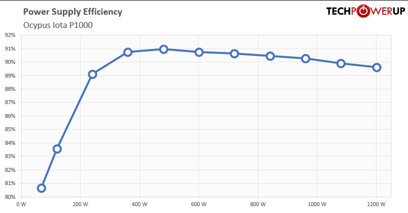
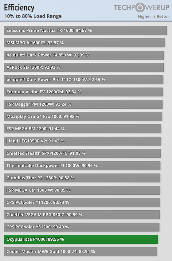
This supply is rated as 80 Plus Gold; however, this will be based on the 115 V measurements. Ocypus do not provide an 80 Plus rating at 230 V, so we will compare the measurements to the 80 Plus Gold (230 V) standard.
| Rated Efficiency Validation (230 V) | ||||
|---|---|---|---|---|
| Certification: 80 Plus Gold | ||||
| Test Load | Required | Measured | Margin | Status |
| 20% | 90.00 % | 89.09 % | -0.91 % | |
| 50% | 92.00 % | 90.73 % | -1.27 % | |
| 100% | 89.00 % | 89.61 % | +0.61 % | Pass |
The requirements for a Gold rating at 230 V are higher than at 115 V, and this PSU comes close in testing, but does not quite pass. There is a likely reason for this, which we will see shortly.
Fan Noise
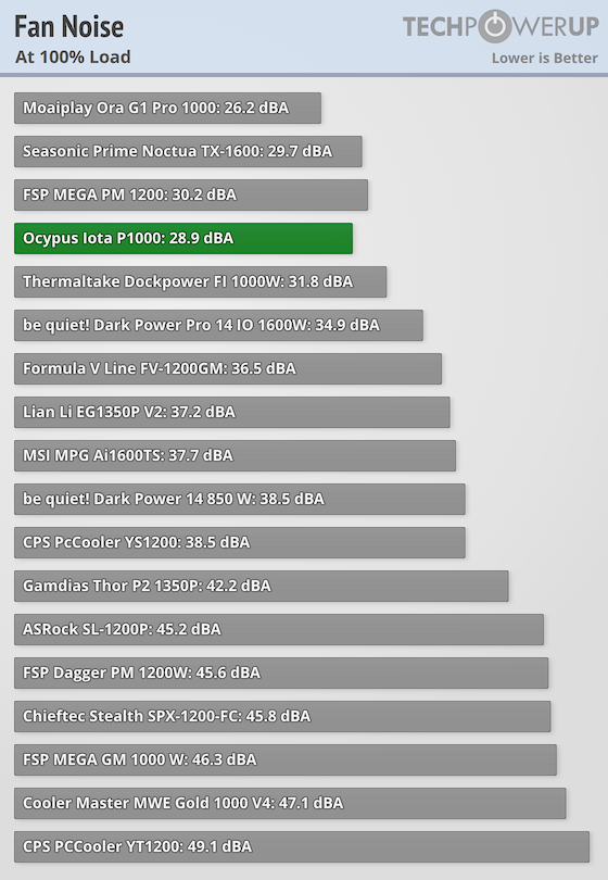
This fan model is known to be lovely and quiet, and Ocypus have gone even further by applying a very relaxed fan curve, resulting in low speeds at full load and practically silent operation in any normal environment. This will be thanks to good heatsink design and placement, and low RDS MOSFETs, meaning less waste heat is generated, and the thermals are able to dissipate without the need for excessive airflow.
Voltage Regulation
All ATX PSUs have a voltage regulation feedback loop, which increases the PWM duty cycle for each rail to account for voltage drop when current is drawn. However, most PSUs only measure voltage at the PSU output, rather than at the end of the cable going to the load. This means any voltage drop across the cable is not automatically adjusted for. The ATX 3.1 specification outlines a maximum allowed voltage drop at the load itself to ensure system stability.| Voltage Regulation & ATX 3.1 Compliance | |||||
|---|---|---|---|---|---|
| Test Load | Rail | Measured | ATX 3.1 Spec Limit | Margin | Status |
| Idle (0%) | +12V | 12.11 V | +5 %/-7 % (11.16 V to 12.60 V) | +0.92 % | Pass |
| +5V | 5.04 V | ±5 % (4.75 V to 5.25 V) | +0.80 % | Pass | |
| +3.3V | 3.37 V | ±5 % (3.14 V to 3.47 V) | +2.12 % | Pass | |
| 100% Load | +12V | 12.02 V | +5 %/-7 % (11.16 V to 12.60 V) | +0.17 % | Pass |
| +5V | 5.14 V | ±5 % (4.75 V to 5.25 V) | +2.80 % | Pass | |
| +3.3V | 3.54 V | ±5 % (3.14 V to 3.47 V) | +7.27 % | Fail | |
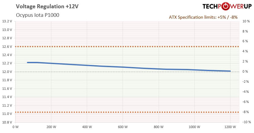
The 12 V and 5 V rails are looking very good; however, under load the 3.3 V rail steps up too high. At idle with no load it is almost dead on target, but as soon as a load is applied the switching behavior inside changes and all rails rise a bit, taking the 3.3 V rail to 3.54 V, above the 3.14–3.47 V range required to fall within ATX specification. With the 12 V rail, the internal regulated voltage is a little over 12 V so that after cable losses it still doesn't sag under 12 V even under full load.
Cable Quality
Although voltage regulation inside modern PSUs is extremely stable, voltage drop and thus power losses will occur across the cables as current is drawn through them. This results in a lower voltage available to the system components than what is actually measured at the PSU outputs. Thicker cables will generally cause less voltage drop—assuming the same grade of cable material—and more power to the components. Any power lost across the cables is wasted as heat in the wire itself. By measuring the voltage drop at a known load, we can calculate the resistance of the cables.| Cable Losses at Full Load | |
|---|---|
| Applied 12 V Load | 88.33 A |
| Measured @ Supply | 12.20 V |
| Measured @ Load | 11.99 V |
| Power Lost in Cable | 18.55 W |
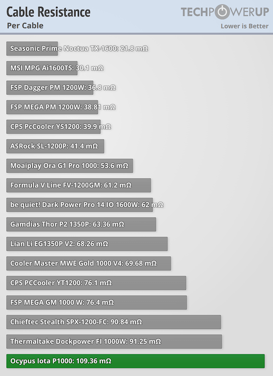
| Per-Cable Resistance | 109.36 mΩ |
| Cable Temperature | 42.0 °C |
This is where we start to see some drawbacks of this model. Initially, the cable resistance is calculated to be very high, but looking at the thermal images, it appears that the current isn't shared very evenly between cables. This will inflate the cable resistance result, as some wires will see more load than others.
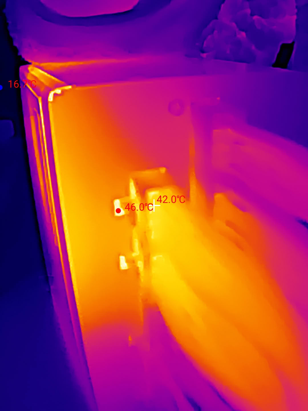
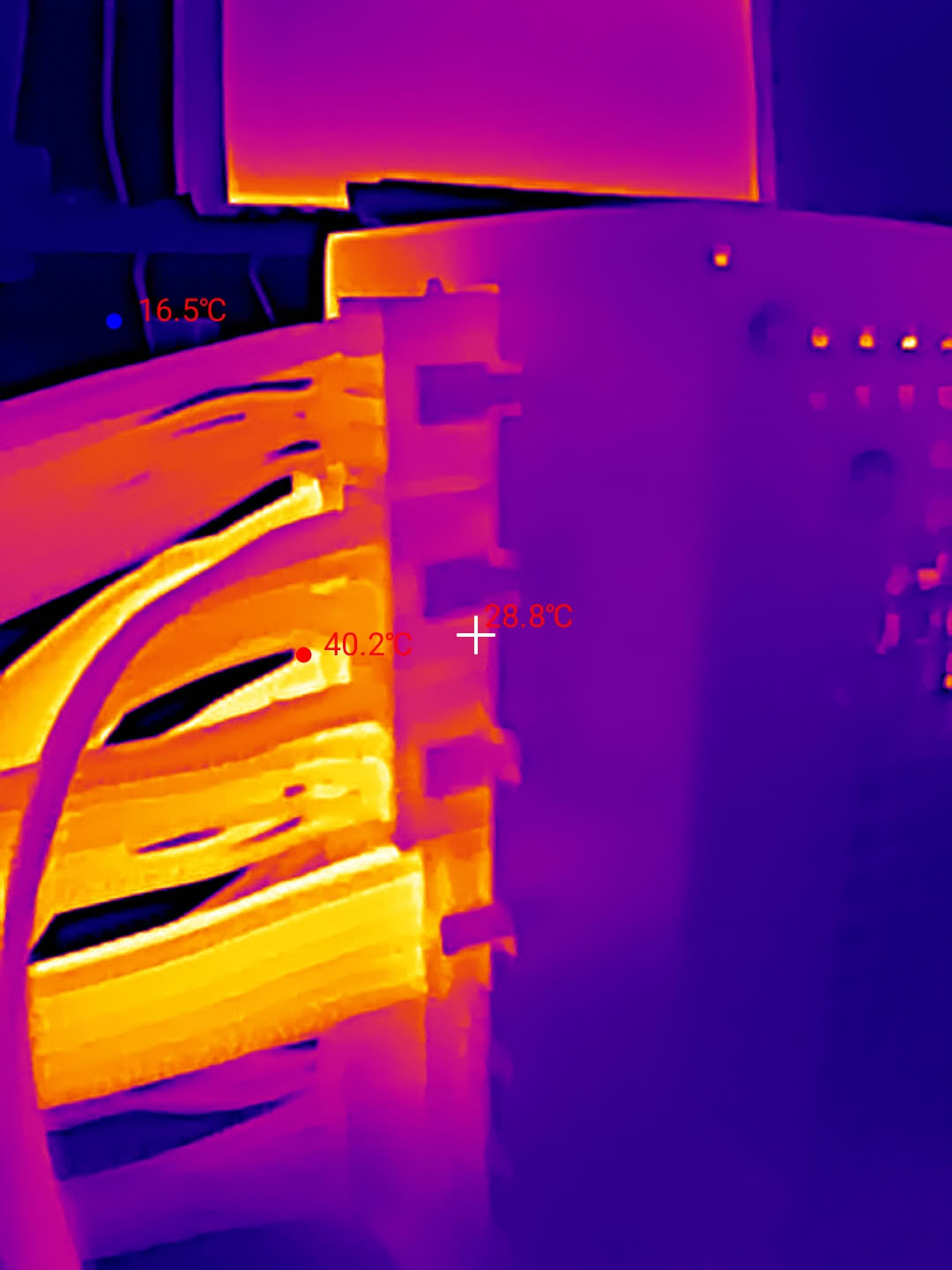
We have quite high relative temperatures at the PSU side. This can be due to trace routing on the connector board, or the connector pins not making a particularly strong connection to the cables. This pin-to-cable connection also forms part of the calculation, so if this is poor then it will increase the resistance result.
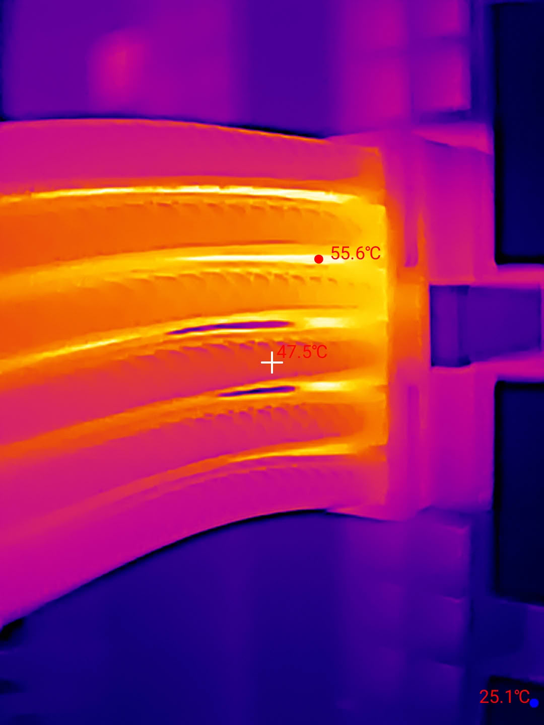
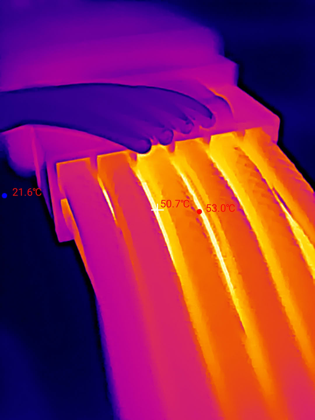
Testing the 12V-2x6 cable alone under a 600 W load, we calculate the individual wire resistance as a much lower 79.2 mΩ. This is likely to be the true cable resistance, and the value earlier was inflated due to uneven current sharing or poor connection quality. This will result in worse overall efficiency as more power is lost here rather than being fed to the load. That being said, the temperature at the 12V-2x6 connector and cables is a bit higher than we are used to seeing; nothing unsafe, but this is an area that could be improved.
Ripple
Ideally you want the DC voltage delivered by your power supply to be a completely flat line when looking through an oscilloscope. However, due to the switching nature of the ATX power supply and the less than ideal real world behavior of all the components involved, we get very small fluctuations in the voltage output, known as ripple and noise. The ATX spec allows a ripple of up to 120 mV for the +12 V rail and 50 mV for the minor rails.| Ripple (mV) | ||||
|---|---|---|---|---|
| Test Load | 12 V | 5 V | 3.3 V | Status |
| 5% | 16 mV | 14 mV | 15 mV | Pass |
| 10% | 15 mV | 16 mV | 14 mV | Pass |
| 20% | 18 mV | 15 mV | 18 mV | Pass |
| 30% | 17 mV | 19 mV | 17 mV | Pass |
| 40% | 21 mV | 18 mV | 21 mV | Pass |
| 50% | 24 mV | 22 mV | 23 mV | Pass |
| 60% | 23 mV | 21 mV | 22 mV | Pass |
| 70% | 27 mV | 25 mV | 26 mV | Pass |
| 80% | 29 mV | 24 mV | 29 mV | Pass |
| 90% | 28 mV | 27 mV | 28 mV | Pass |
| 100% | 34 mV | 29 mV | 32 mV | Pass |
| 110% | 38 mV | 32 mV | 36 mV | Pass |
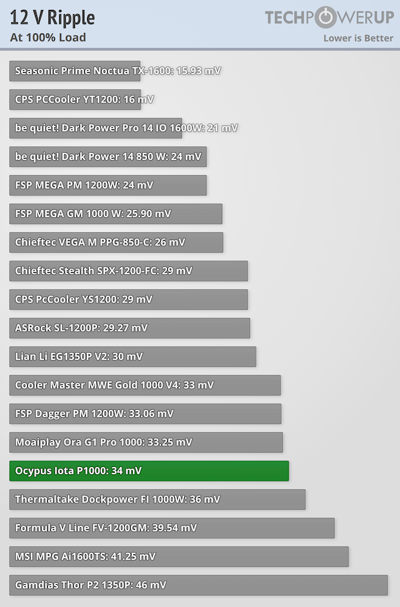
Ripple is handled just fine, with all rails kept well within ATX specifications. The 3.3 V and 5 V rails are a touch higher than other similar models but nothing of concern.
Short Circuit Protection
Short circuit protection is one of the most fundamental and important protections for a power supply. If a short circuit is detected on any rails, the PSU should turn off and prevent damage to itself and other components.| Short Circuit Protection | |
|---|---|
| +12 V rail | Operational |
| +5 V rail | Operational |
| +3.3 V rail | Operational |
SCP worked as expected with the unit.
Nov 19th, 2026 18:04 CST
change timezone
Latest GPU Drivers
New Forum Posts
- Building a hardware monitor, diagnostics and benchmark tool – would you use it? (29)
- Dual B70 or Dual R9700 Pro on Linux (11)
- How to prevent OLED burn damage due to PC freezes or power outtages? (30)
- TPU's Nostalgic Hardware Club (22170)
- Security Apps (3)
- Got the EOL 32GB TridentZ 6000 CL26 1.4V (12)
- Honestly, do you care about GTA VI? (167)
- Dell Workstation Owners Club (3517)
- Making a game in Godot engine (6)
- Introducing DST Bench : one of the most advanced disk benchmark and storage analyzer real-time software (6)
Popular Reviews
- Acemagic Retro X3 Review
- Ugreen NASync DXP4800 GT Review
- Upcoming Hardware Launches 2027 (Updated Nov 2026)
- Pulsar Office Tour & First Look at P1 Dual-Sensor Mouse
- AMD Zen 6 Technical Deep Dive
- Biwin Black Opal NV7400 2 TB Review
- Corsair RM1200e (Second Generation) Review
- Sapphire Radeon RX 7700 XT Pure Review
- Sapphire Radeon RX 7700 XT Pulse Review
- AMD Ryzen 7 9800X3D Review - The Best Gaming Processor
TPU on YouTube
Controversial News Posts
- NVIDIA Co-Founder and CEO Jensen Huang Officially Resigns (489)
- Report: Jensen Huang Eyes NVIDIA Comeback (223)
- Open Letter Asking NVIDIA to Reinstate Jensen Huang Passes 115,000 Signatures (184)
- OpenAI CEO Argues Home PCs Waste the World's Limited DRAM Supply (152)
- NVIDIA Launches Investigation Into Jensen Huang's Relationship With Suspected Chinese Spy (136)
- Intel "Raptor Lake Next" 16-Core and 20-Core CPUs Surface (130)
- Legendary Game Studio BioWare Shuts Down Following EA Layoffs (104)
- Dell CEO Says the Memory Shortage Will Get Worse in 2027 (95)