 0
0
Super Flower Leadex III ARGB Gold 750 W Review
Protection Features, Power Sequencing & EMC »Advanced Transient Response Tests
In these tests, we monitor the response of the PSU in two different scenarios. First, a transient load (15 A at +12V, 6 A at +5V, 6 A at +3.3V, and 0.5 A at 5VSB) is applied to the PSU for 20 ms while it is working at 20% load. In the second scenario, the PSU, while working at 50% load, is hit by the same transient load. In both tests, our oscilloscope measures the voltage drops caused by the transient load. All voltages should remain within the regulation limits defined by the ATX specification.During real-world usage, a PSU always operates under changing loads, depending on whether the CPU or graphics card is busy. It is of immense importance that the PSU is able to keep its rails within the limits defined by the ATX specification. Smaller deviations reduce stress being applied to system components.
We should note that the ATX specification requires for capacitive loading during the transient tests, but in our methodology, we chose to apply the worst-case scenario with no extra capacitance on the rails. Although the ATX specification asks for this capacitance, your system—the mainboard and its other parts—may not provide it, which we have to keep in mind as well.
| Advanced Transient Response 20% - 50 Hz | ||||
|---|---|---|---|---|
| Voltage | Before | After | Change | Pass/Fail |
| 12 V | 12.113V | 11.988V | 1.03% | Pass |
| 5 V | 5.016V | 4.902V | 2.27% | Pass |
| 3.3 V | 3.306V | 3.171V | 4.08% | Pass |
| 5VSB | 5.067V | 5.027V | 0.79% | Pass |
| Advanced Transient Response 50% - 50 Hz | ||||
|---|---|---|---|---|
| Voltage | Before | After | Change | Pass/Fail |
| 12 V | 12.096V | 11.970V | 1.04% | Pass |
| 5 V | 5.006V | 4.889V | 2.34% | Pass |
| 3.3 V | 3.295V | 3.155V | 4.25% | Pass |
| 5VSB | 5.027V | 4.970V | 1.13% | Pass |
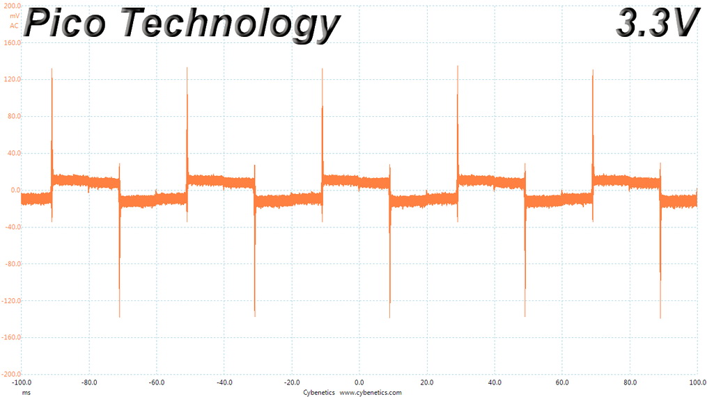
Super Flower platforms usually have good transient response at +12 V, and this one does as well. With only a deviation of close to 1% on this rail in both tests, I am fully satisfied as far as this rail is concerned. Deviations remain low on the 5 V and 5VSB rails as well, but the 3.3 V rail deviates by more than 4%, which has its voltage drop below 3.2 V in all these tests.
Below are the oscilloscope screenshots we took during Advanced Transient Response testing.
Transient Response at 20% Load
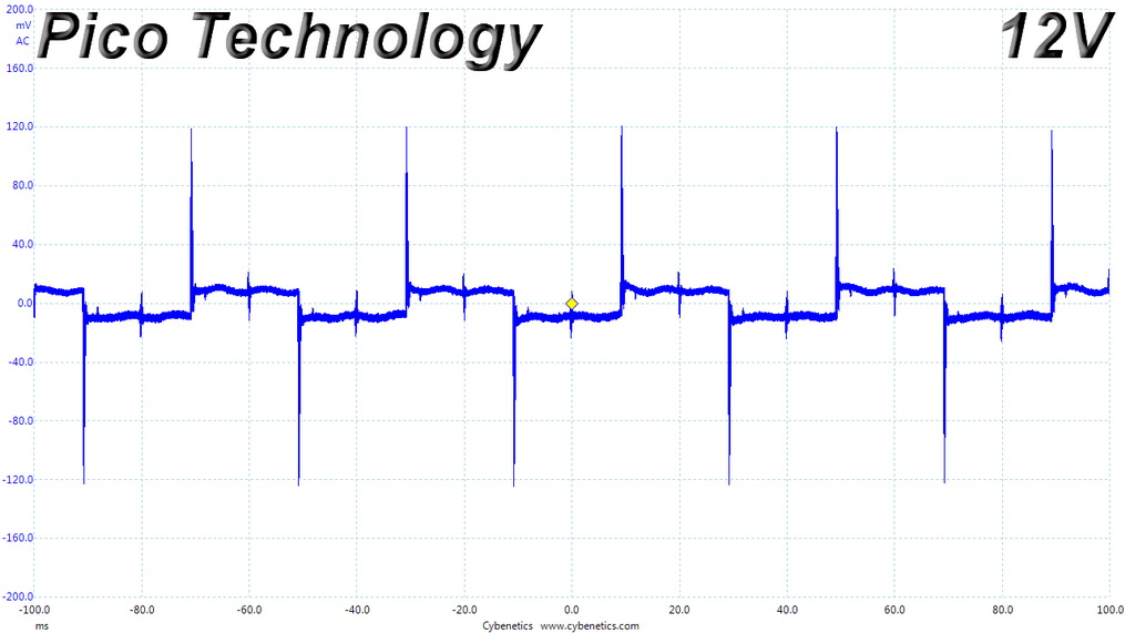

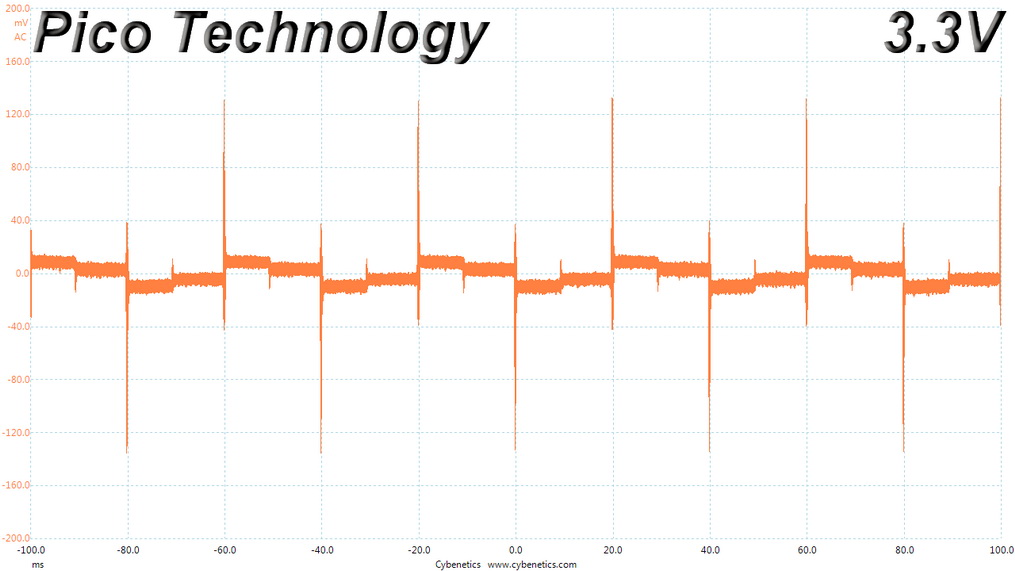
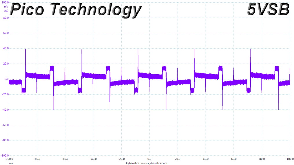
Transient Response at 50% Load


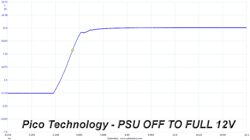
Turn-on Transient Tests
We measure the response of the PSU in more straightforward scenarios of transient load—during the power-on phase of the PSU—in the next set of tests. In the first test, we turn the PSU off, dial the maximum current the 5VSB can output, and then switch on the PSU. In the second test, we dial the maximum load +12V can handle and start the PSU while the PSU is in standby mode. In the last test, while the PSU is completely switched off (we cut off power or switch the PSU off by flipping its on/off switch), we dial the maximum load the +12V rail can handle before switching the PSU on from the loader and restoring power. The ATX specification states that recorded spikes on all rails should not exceed 10% of their nominal values (e.g., +10% for +12V is 13.2 V and 5.5 V for +5V).

Inrush Current
Inrush current, or switch-on surge, refers to the maximum, instantaneous input current drawn by an electrical device when it is first turned on. Large enough inrush current can cause the tripping of circuit breakers and fuses and may also damage switches, relays, and bridge rectifiers. As a result, the lower the inrush current of a PSU right as it is turned on, the better.
Inrush current levels are normal for the capacity of the bulk caps.
Apr 27th, 2024 18:43 EDT
change timezone
Latest GPU Drivers
New Forum Posts
- Best SSD for system drive (107)
- On ACER V3-772G GDDR5 laptop no display (1)
- Schede video/ grafiche rtx 3080 e rx 6800xt (3)
- Anyone know if Rufus gets around the SSE4.2 issue with Windows 11 24H2? (7)
- Core PL1 + GPU PL1 + Ring EDP OTHER (11)
- Which air cooler for a ryzen 9 5900x (168)
- Black screens leading to restarts (Event ID 18) on AMD platform since changing graphics card (45)
- Usb 3.2 and usbc speeds became very slow (6)
- Looking for recommendations to upgrade the GPU (16)
- Should I install Windows 10 or 11 for my new device (56)
Popular Reviews
- Ugreen NASync DXP4800 Plus Review
- HYTE THICC Q60 240 mm AIO Review
- Upcoming Hardware Launches 2023 (Updated Feb 2024)
- MOONDROP x Crinacle DUSK In-Ear Monitors Review - The Last 5%
- Thermalright Phantom Spirit 120 EVO Review
- FiiO K19 Desktop DAC/Headphone Amplifier Review
- AMD Ryzen 7 7800X3D Review - The Best Gaming CPU
- Alienware Pro Wireless Gaming Keyboard Review
- ASUS Radeon RX 7900 GRE TUF OC Review
- Gigabyte GeForce RTX 4070 Ti Super Gaming OC Review
Controversial News Posts
- Windows 11 Now Officially Adware as Microsoft Embeds Ads in the Start Menu (139)
- Sony PlayStation 5 Pro Specifications Confirmed, Console Arrives Before Holidays (117)
- NVIDIA Points Intel Raptor Lake CPU Users to Get Help from Intel Amid System Instability Issues (106)
- AMD "Strix Halo" Zen 5 Mobile Processor Pictured: Chiplet-based, Uses 256-bit LPDDR5X (103)
- US Government Wants Nuclear Plants to Offload AI Data Center Expansion (98)
- AMD's RDNA 4 GPUs Could Stick with 18 Gbps GDDR6 Memory (95)
- Developers of Outpost Infinity Siege Recommend Underclocking i9-13900K and i9-14900K for Stability on Machines with RTX 4090 (85)
- Windows 10 Security Updates to Cost $61 After 2025, $427 by 2028 (84)