 1
XMG Focus 17 (M25) Review - Proves that the 17.3-inchers Are Still a Thing
Display Testing »Disassembly and Teardown
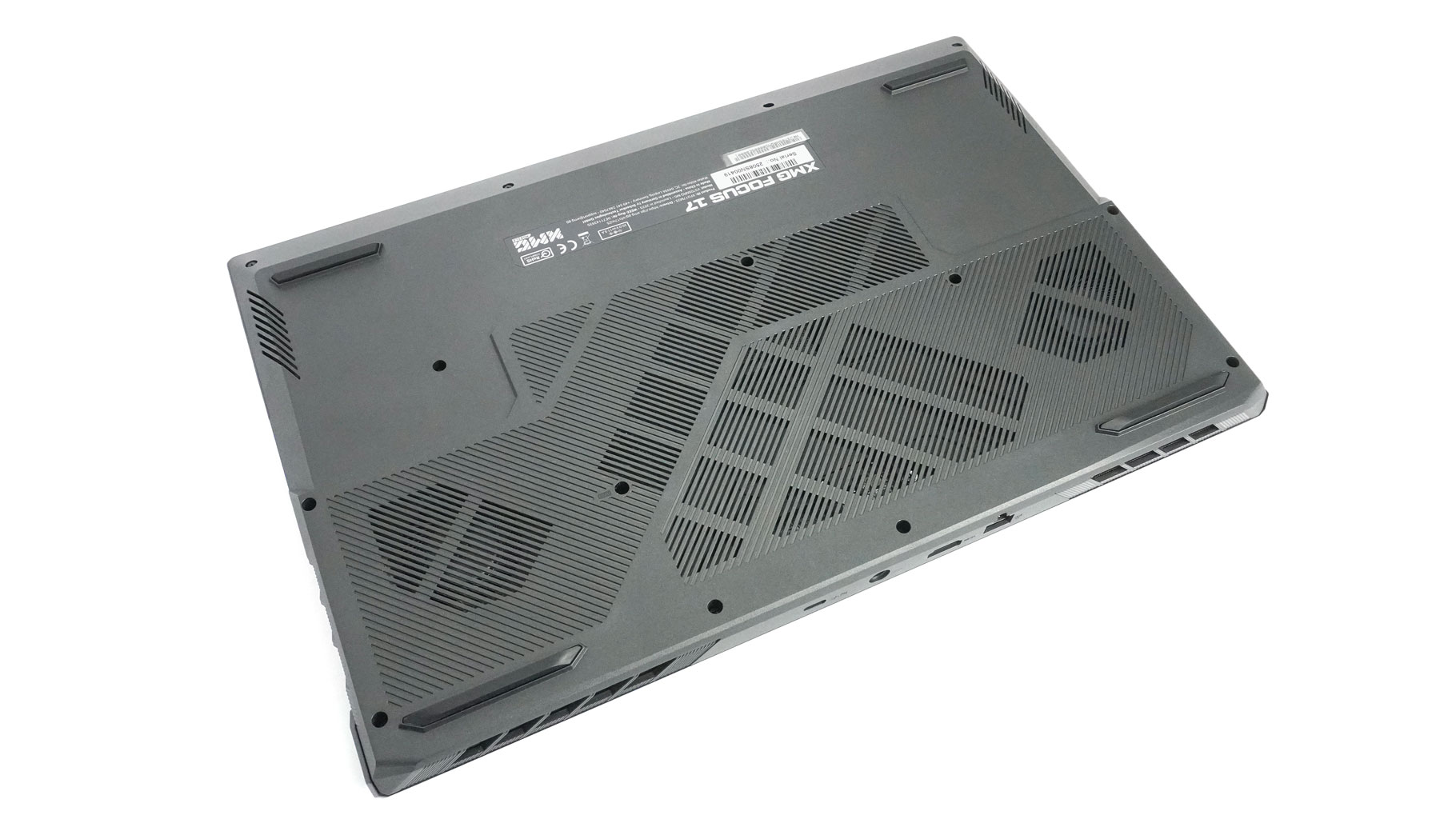
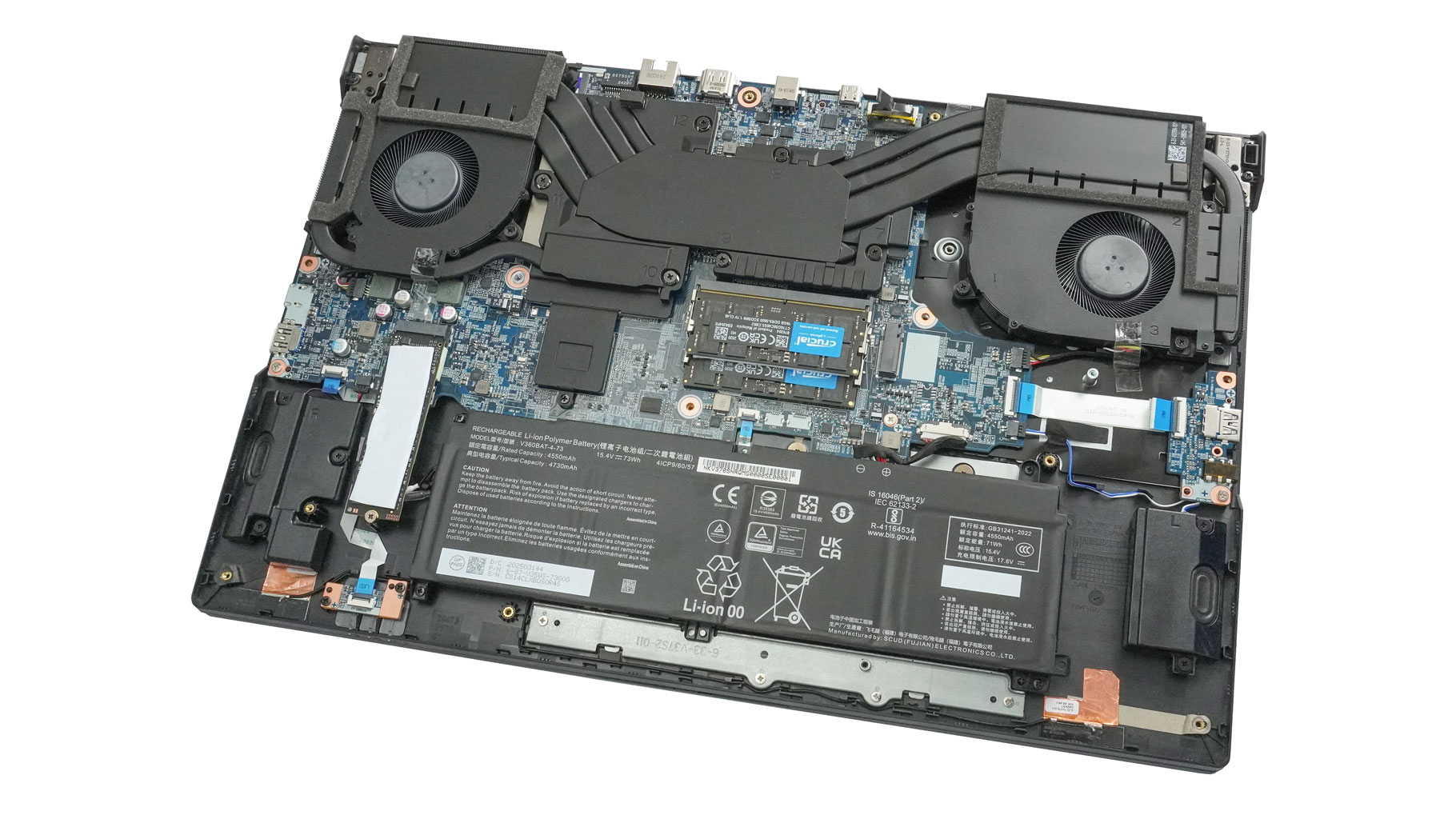
Let's see how to open the XMG Focus 17 M25 for upgrading the internals or just simple cleaning. Removing the bottom plate is business as usual—14 Philips-head screws hold it to the chassis. Next, hold the rear exhaust vents firmly and pop them off, either one by one or all at once. Gently raise the plate, wiggle it a bit, and this should be enough. If that doesn't work, gently pry the spots where the internal clips are still connected using a thin plastic tool.
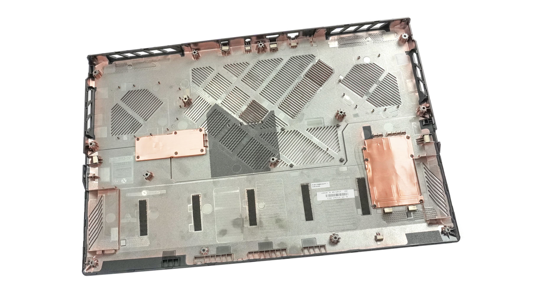
The bottom plate houses two cooling plates on the inside that are meant to make contact with the SSD thermal pads. Five small soft paddings are positioned above the battery. There is also a dust filter in the middle.
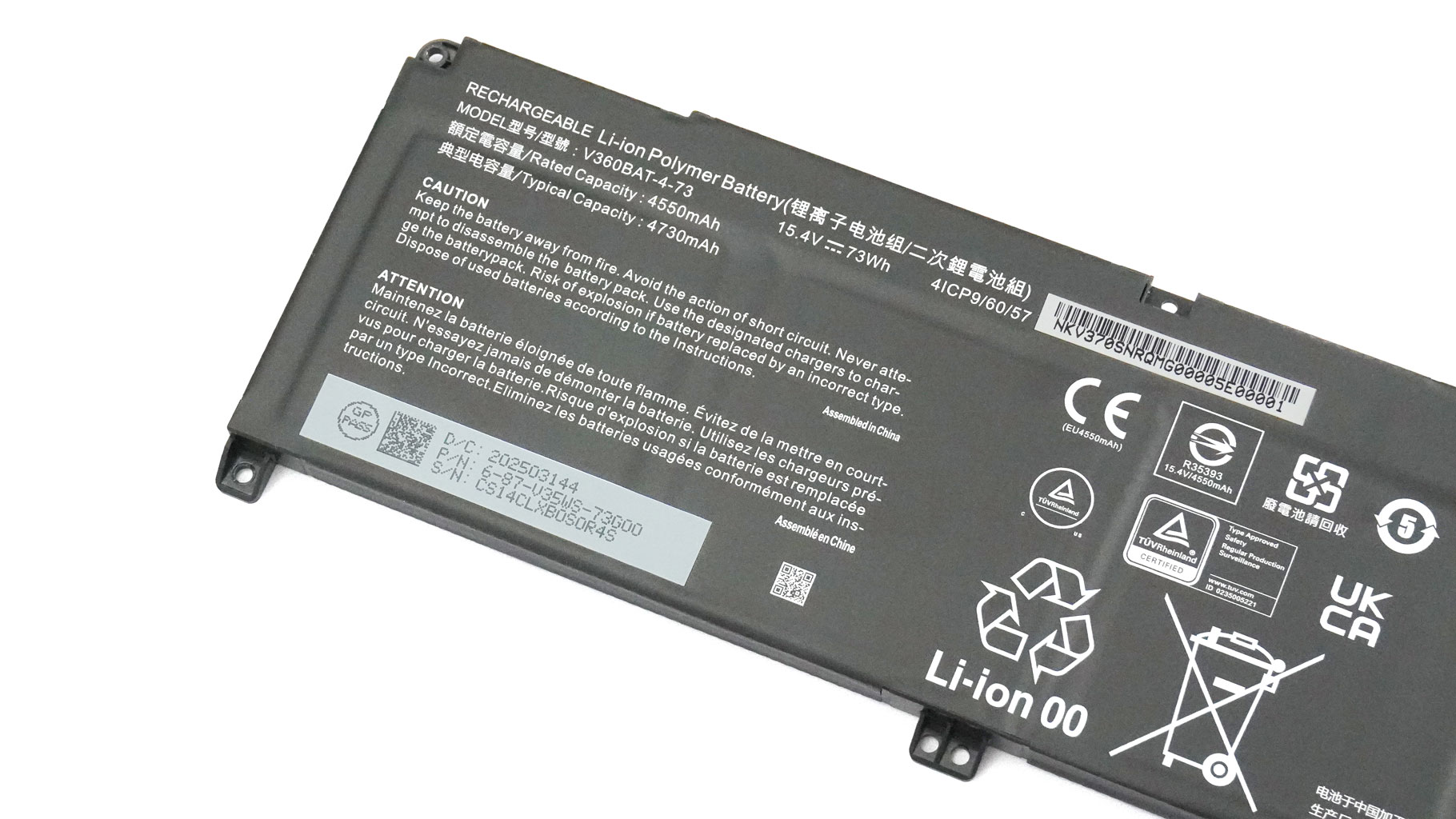
The battery here is a 73 Wh unit.
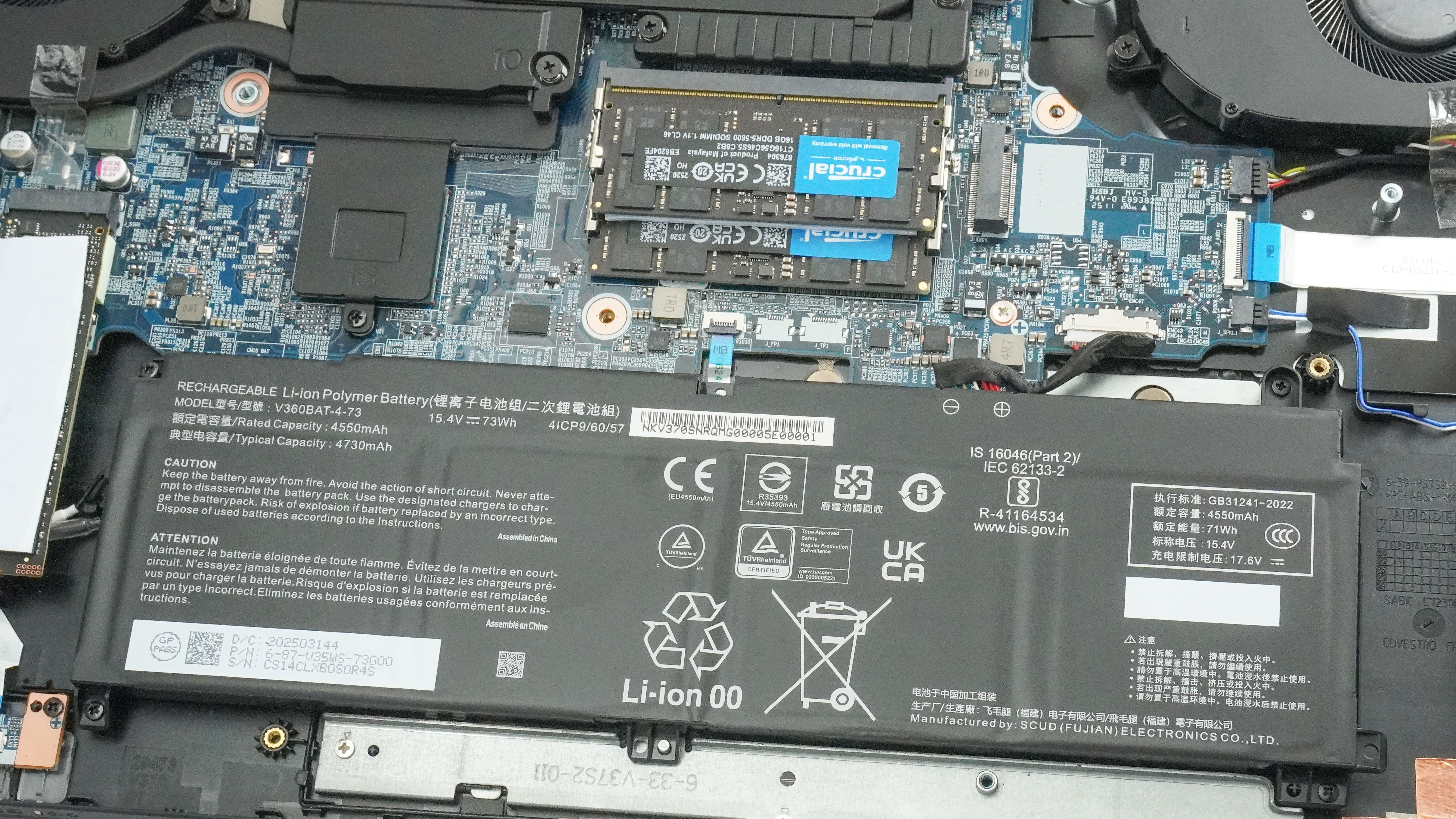
To take it out, pull down the connector and undo the four Philips head screws that fix the unit to the base.
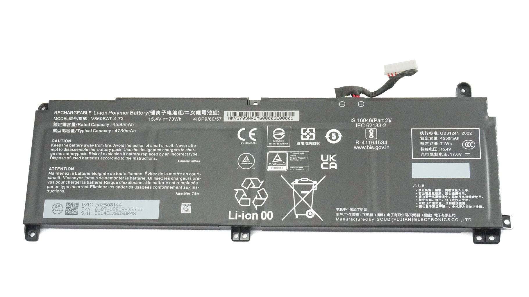
The autonomous life on a single charge isn't long - just 3 hours and 42 minutes of 4K YouTube video playback.
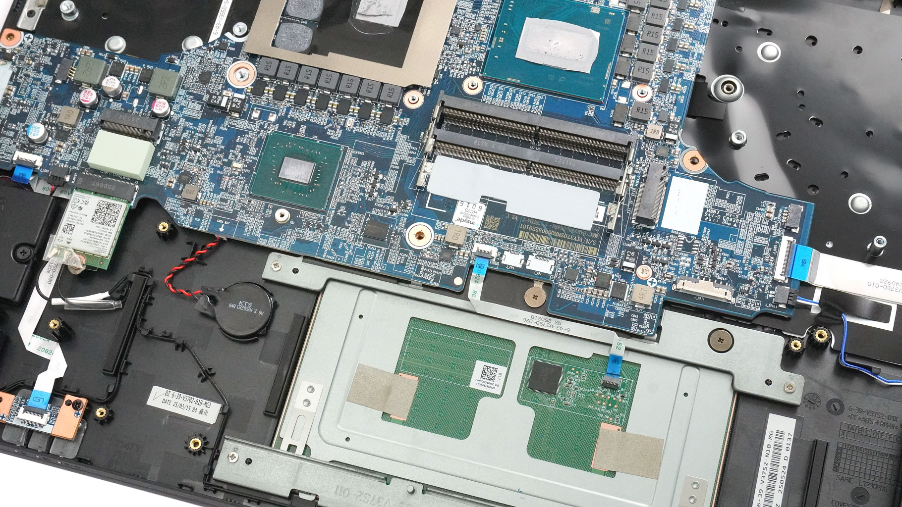
Here are all the upgrade options in one picture.
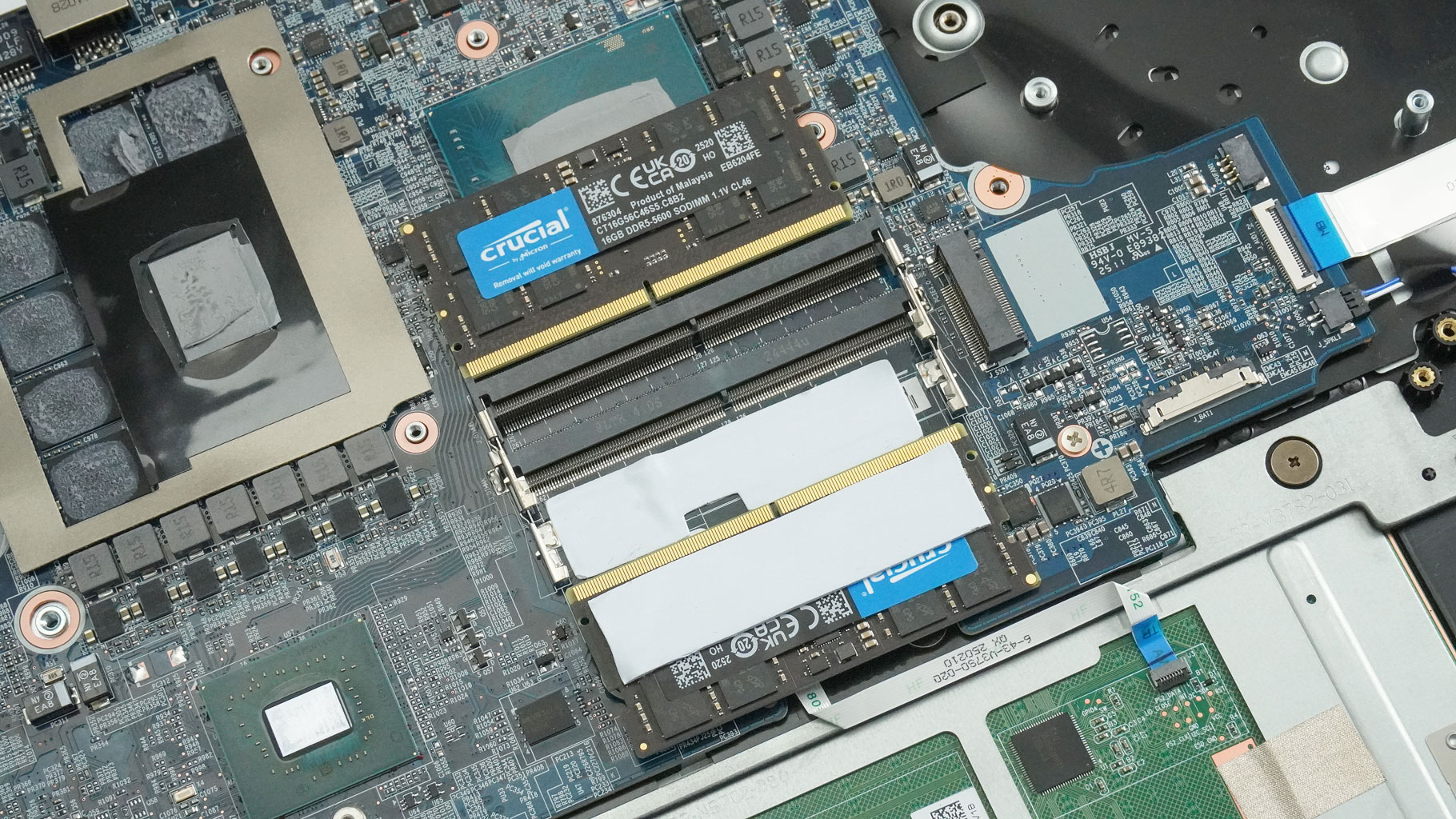
The two SODIMM slots can take up to a combined total 96 GB of DDR5-5600 memory, using two 48 GB modules.
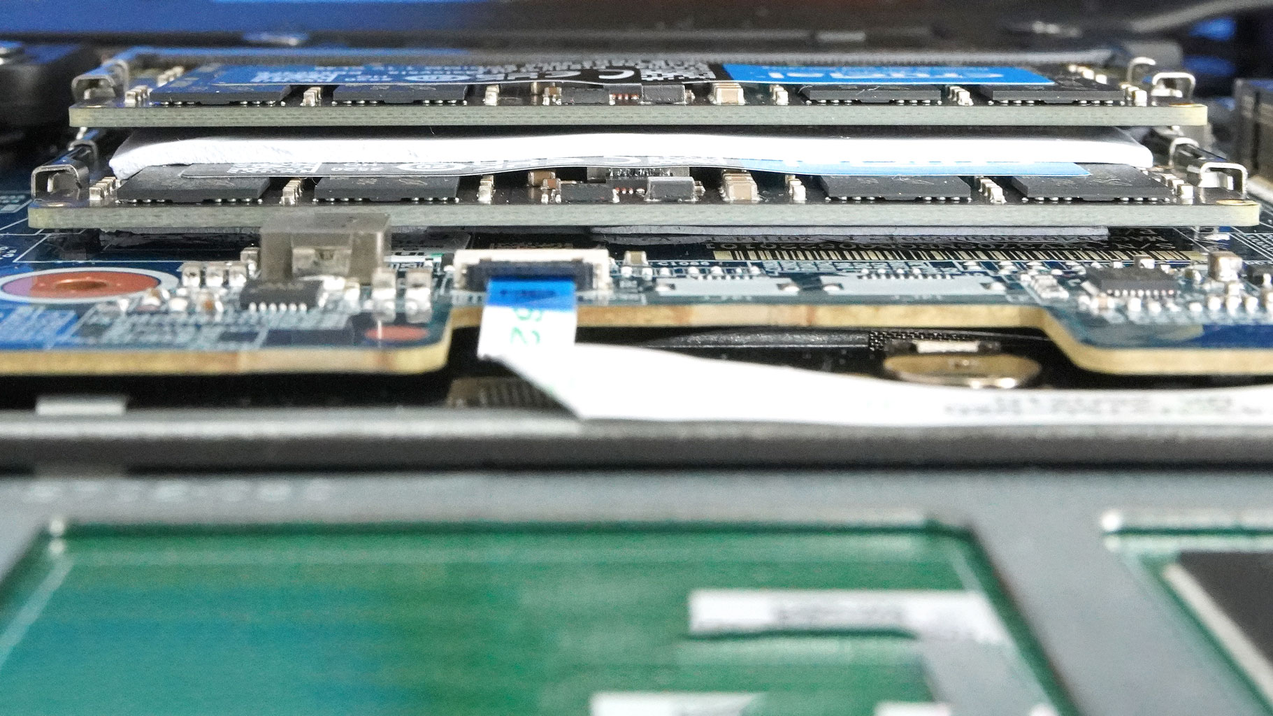
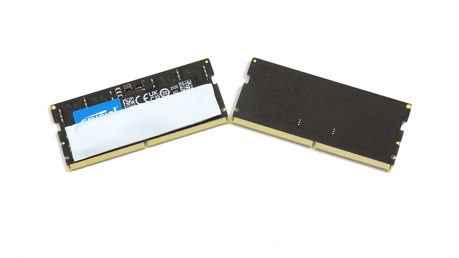
The bottom stick is cooled on both sides, while the top one relies on fresh air coming in from the top ventilation grille.
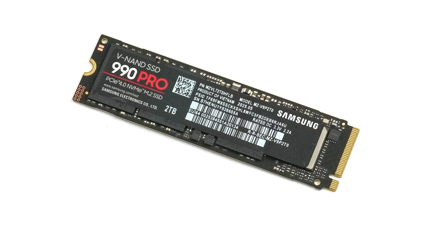
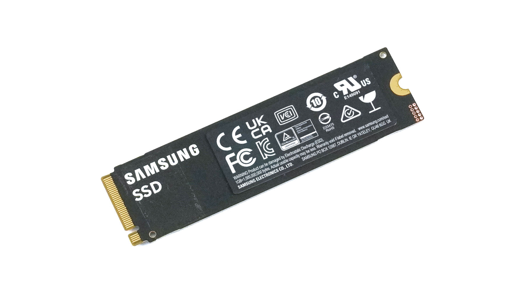
You get two 2280 M.2 slots compatible with Gen 4 drives. The system NVMe has a long thermal pad on top. Another smaller pad is placed underneath.
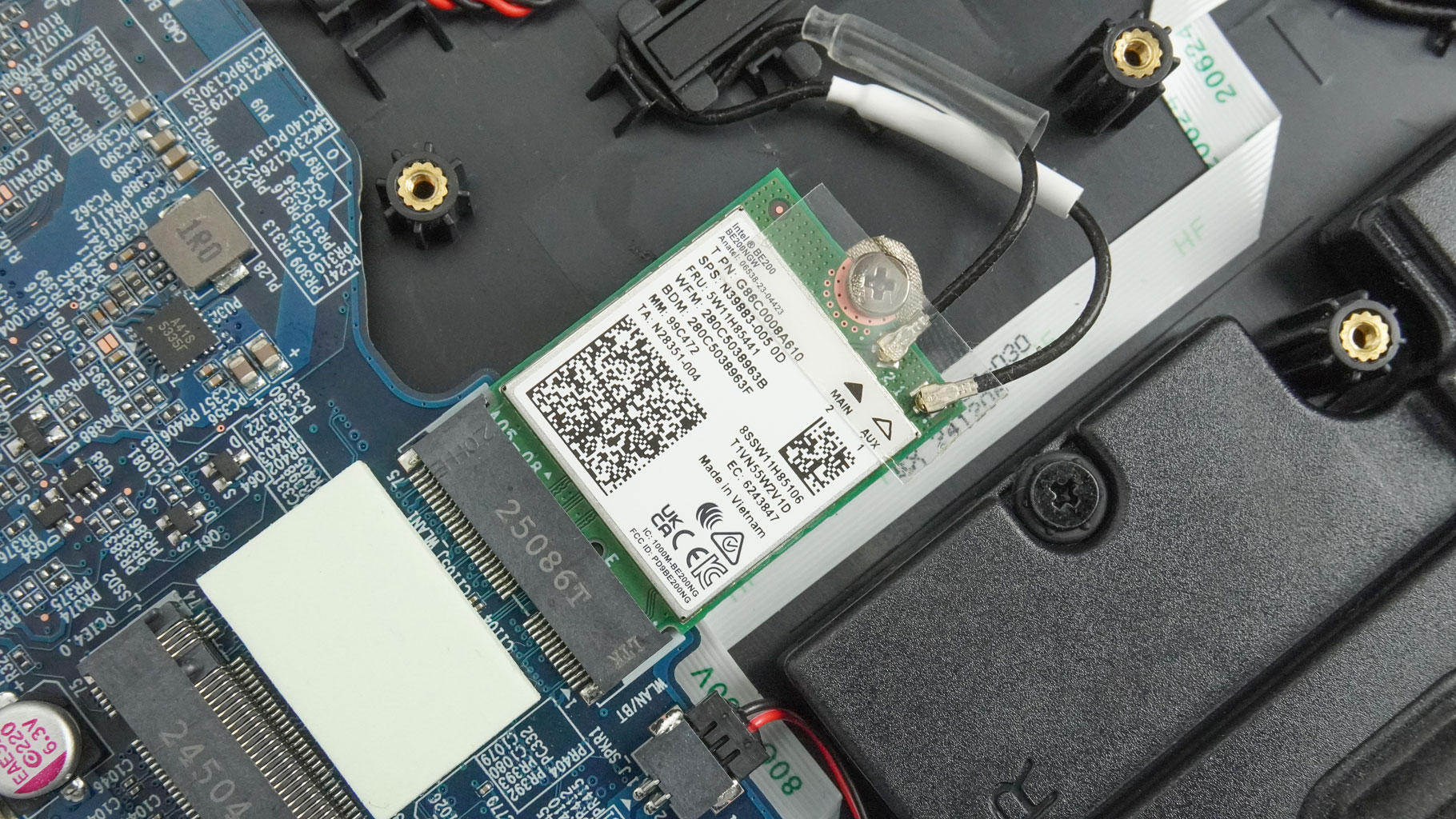
This also reveals that the user-replaceable Wi-Fi 7 card is positioned in front of the slot, and the NVMe drive almost completely covers it. This may lead to connection issues, though I personally didn't experience any.
The cooling looks pretty substantial. It comprises two 60 mm fans, four heatsinks, one extra-thick heat pipe shared between the CPU and the GPU, two solely dedicated to the graphics card, and two more for the processor that also extend over the GPU. The chipset is also cooled. Two huge metal plates are positioned above the processor and the video card chips. A long heat spreader connects them to the top.
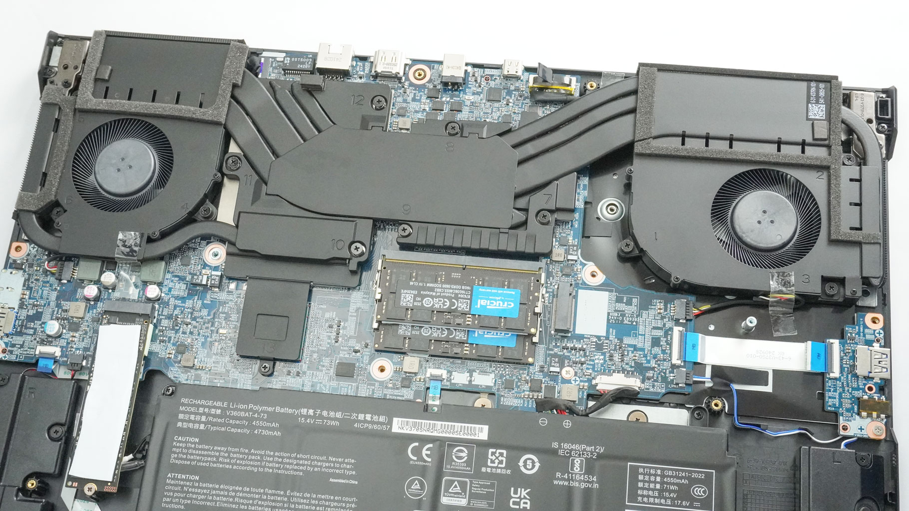
Now, let's remove the thermal system. Pull out the fan connectors and unglue the surrounding tape. Undo three Philips heads for each fan. Next, there are two trios of screws around each chip and one below the chipset. Pry the back of the cooling with a lever tool and lift it away from the chassis.
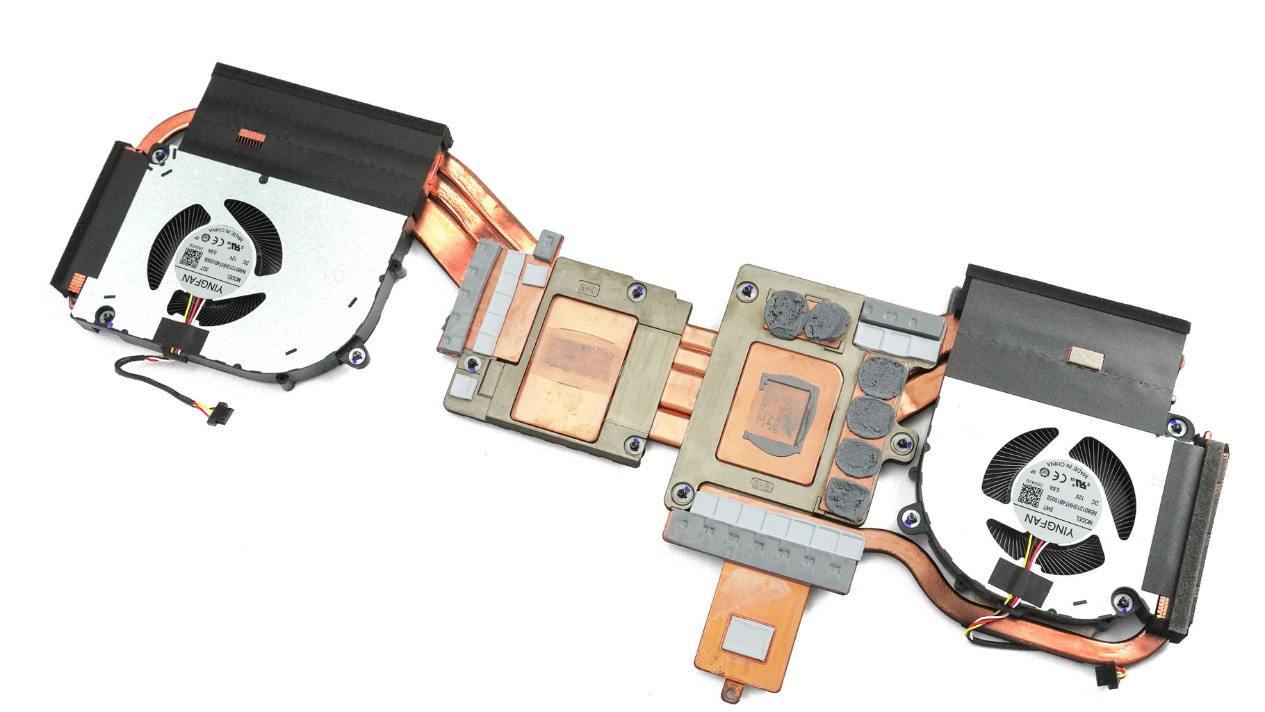
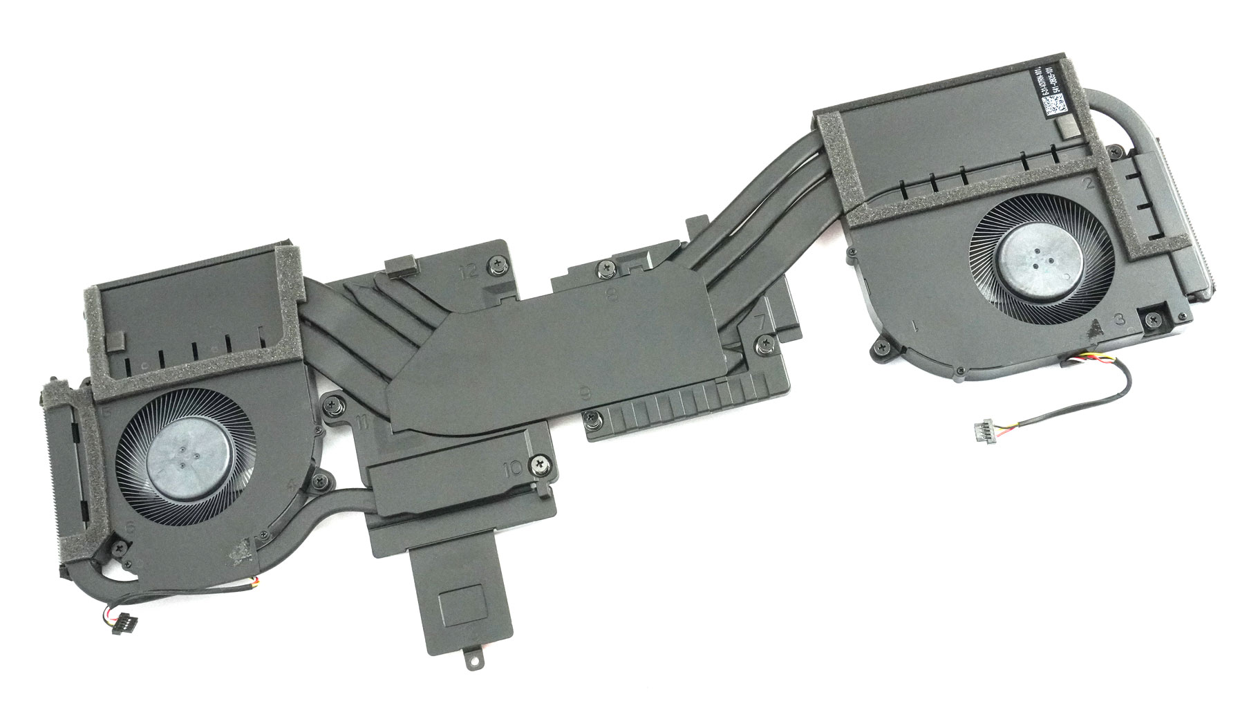
That's the bottom view of the thermal system. The heat pipes and the heat sinks are made of copper.
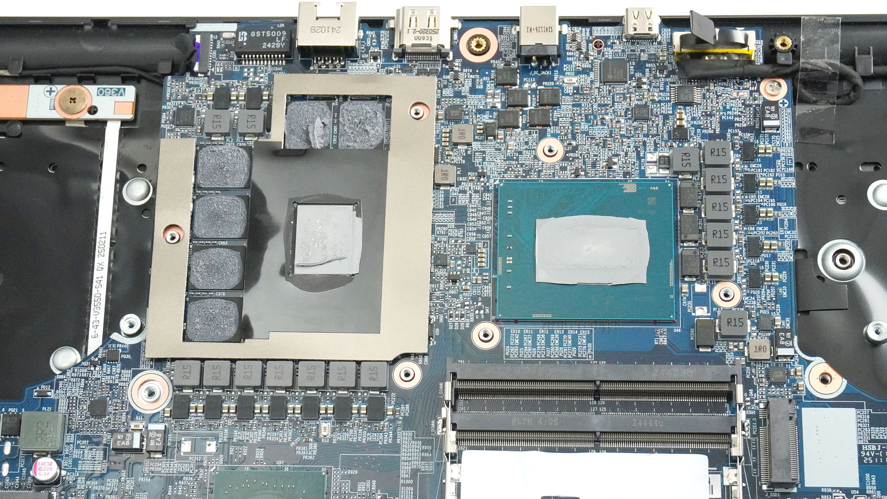
PTM7950 thermal compound is applied to the CPU and the GPU.
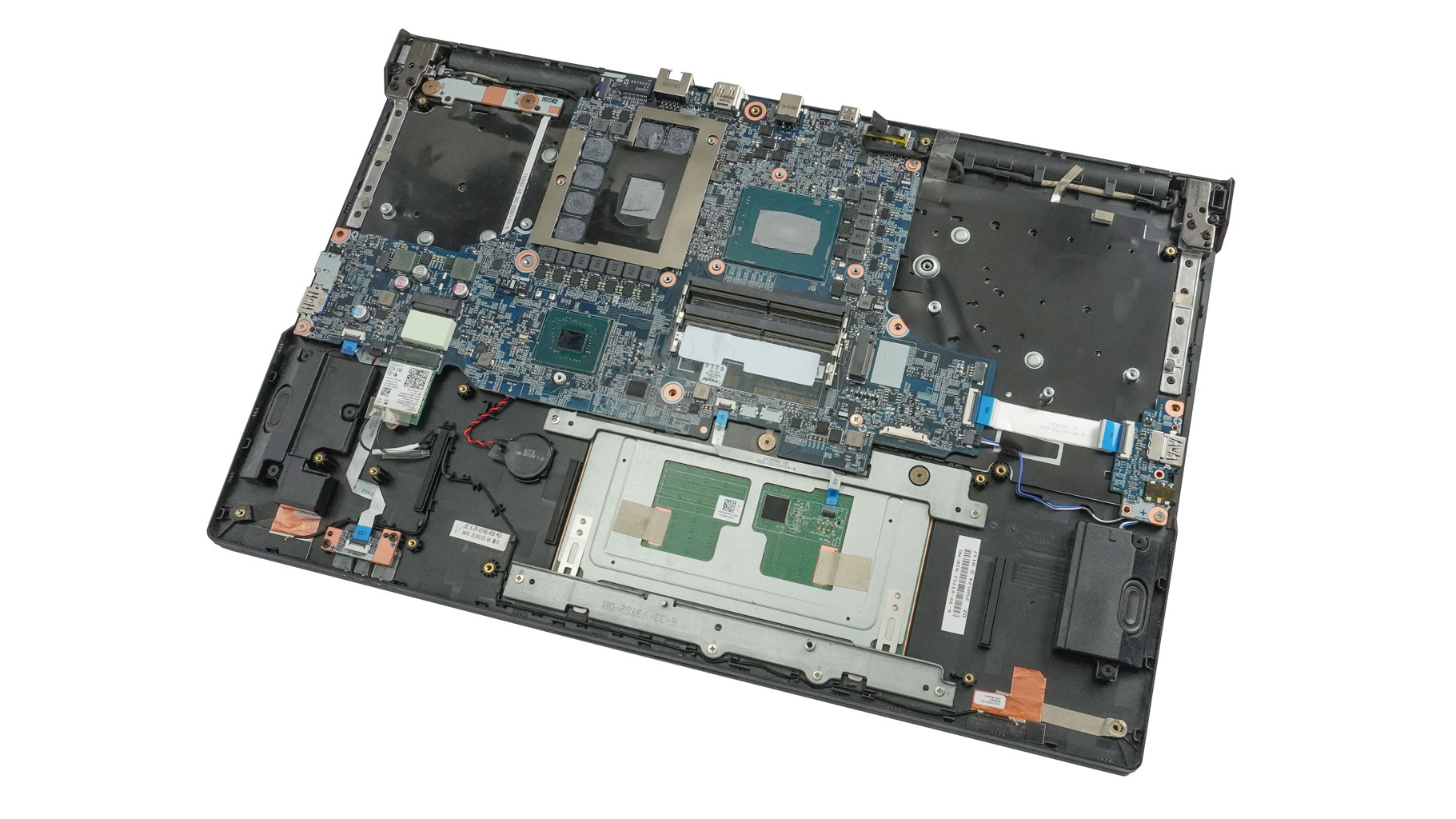
The holes on the fan sockets hint that fresh air is also drawn through the keycaps.
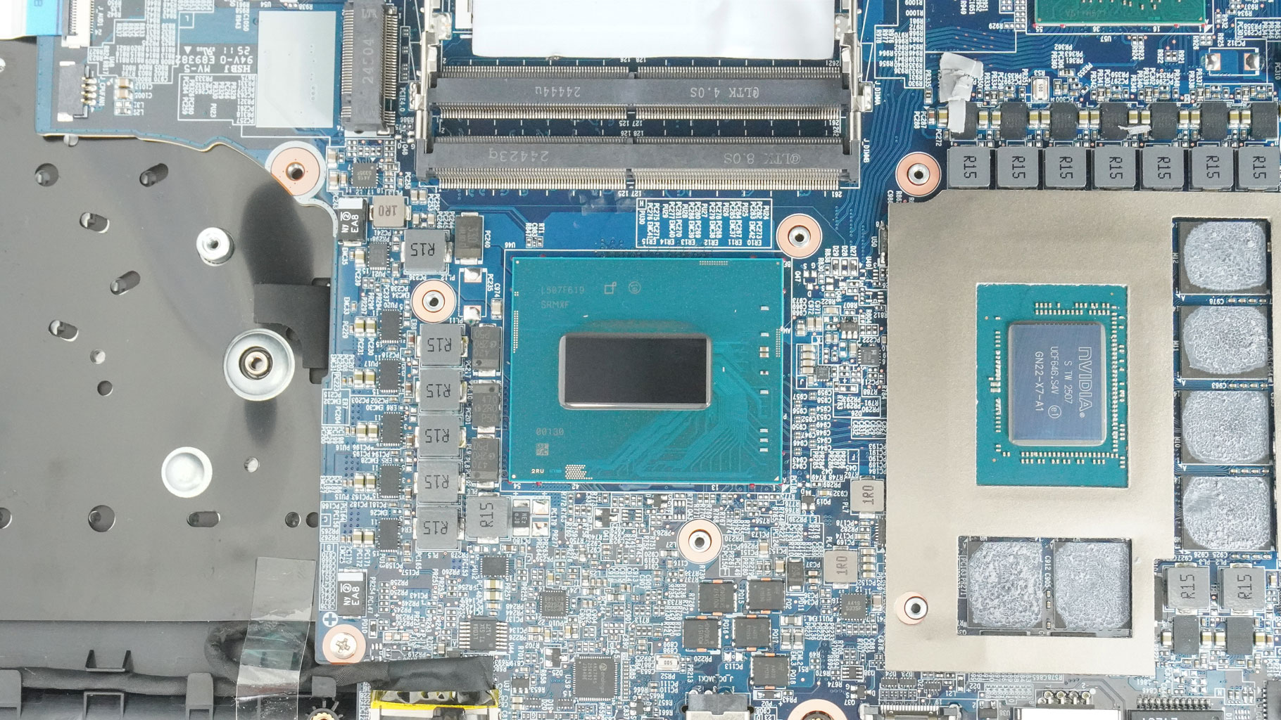
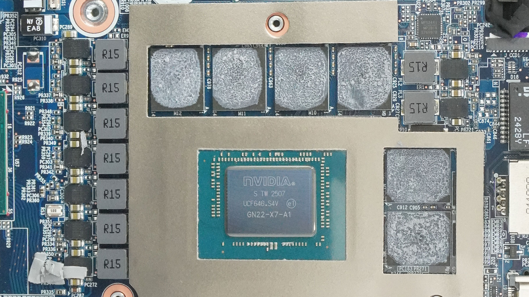
You can take a closer look at the processor and the graphics card.
Nov 21st, 2026 05:01 PST
change timezone
Latest GPU Drivers
New Forum Posts
- Without Jensen, PC gaming will be (53)
- Anthrophics IPO (30)
- WarpCoreBench scores! (88)
- What's your latest tech Freebie? (86)
- TPU's Nostalgic Hardware Club (22179)
- [Poll] 12V-2x6 Connector Protection: What Are You Using? (WireView / Ampinel / Equalizer / Other / Nothing) (50)
- UPS what one to get? (1)
- RX 9000 series GPU Owners Club (2252)
- Windows 11 General Discussion (7743)
- Zen 3 IF/IMC degradation (242)
Popular Reviews
- Microsoft Surface Laptop Ultra Review - The Next-gen Arm Laptop
- Ugreen NASync DXP4800 GT Review
- Corsair RM1200e (Second Generation) Review
- Pulsar Office Tour & First Look at P1 Dual-Sensor Mouse
- Upcoming Hardware Launches 2027 (Updated Nov 2026)
- Acemagic Retro X3 Review
- Biwin Black Opal NV7400 2 TB Review
- AMD Ryzen 7 9800X3D Review - The Best Gaming Processor
- AMD Zen 6 Technical Deep Dive
- Chieftec Iceberg PRO 360 DARK Review
TPU on YouTube
Controversial News Posts
- NVIDIA Co-Founder and CEO Jensen Huang Officially Resigns (491)
- Report: Jensen Huang Eyes NVIDIA Comeback (258)
- Open Letter Asking NVIDIA to Reinstate Jensen Huang Passes 115,000 Signatures (184)
- OpenAI CEO Argues Home PCs Waste the World's Limited DRAM Supply (152)
- NVIDIA Launches Investigation Into Jensen Huang's Relationship With Suspected Chinese Spy (136)
- Intel "Raptor Lake Next" 16-Core and 20-Core CPUs Surface (130)
- Legendary Game Studio BioWare Shuts Down Following EA Layoffs (104)
- NVIDIA GeForce RTX 50-Series Scheduled for up to $500 Price Hike This Week (89)