 0
0
Antec HCG-620M 620 W Review
Voltage Regulation & Efficiency »A Look Inside
Before reading this page we strongly suggest to take a look at this article, which will help you understand the internal components of a PSU much better.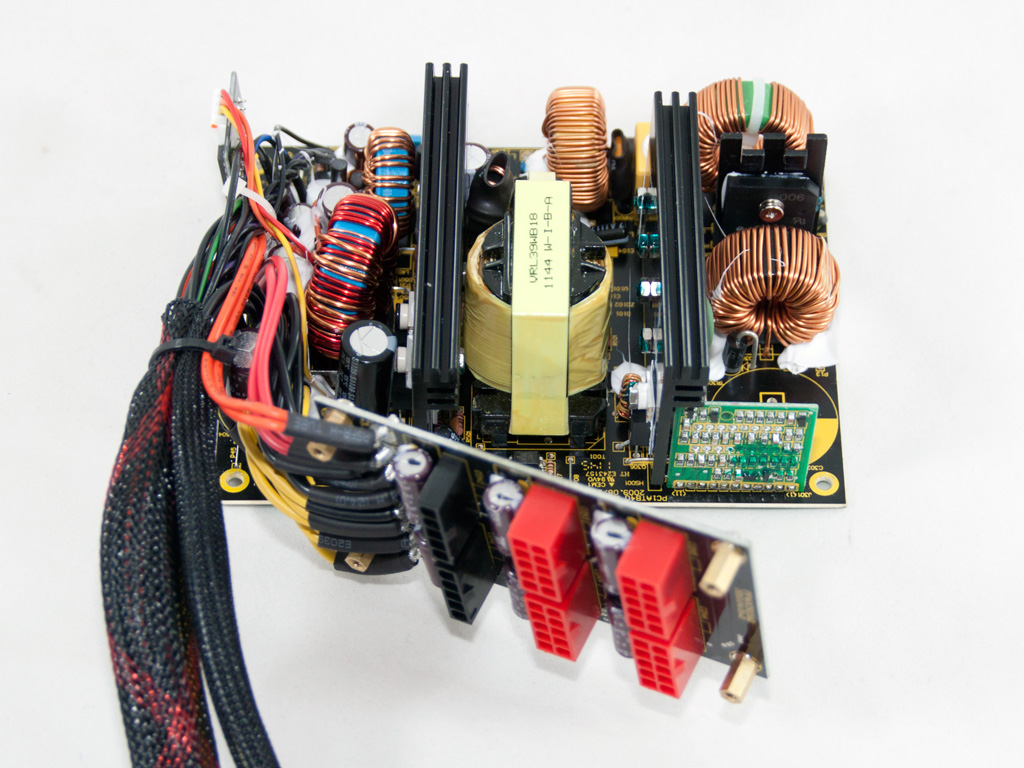


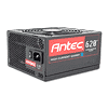
The OEM of this unit is the highly experienced Seasonic, which also manufactures the older, non modular, High Current Gamer PSUs with up to 620W capacity. Actually the HCG-620M is a Seasonic M12II-620 with minor differences mostly on the modular PCB, so it uses the same outdated double forward group regulation design. Nothing is wrong with the classic double forward configuration of the primary switchers since the PSU's efficiency rating is not so high but we do have a problem with the group regulation design which greatly affects performance at unbalanced loads. Finally, as you can see the main PCB is really small so it could easily fit in a much smaller enclosure.
Behind the AC receptacle there is a small PCB housing the first part of the transient filter. There we find one X and two Y caps and a CM choke. On the main PCB more transient filtering components can be found, namely one X and two Y caps, two CM chokes and an MOV. Apparently the transient filtering stage is over-complete.

The single bridge rectifier, a GBU 1006, is bolted on a dedicated heatsink. It can handle up to 10Amps so it will easily cope with the PSU's max capacity.
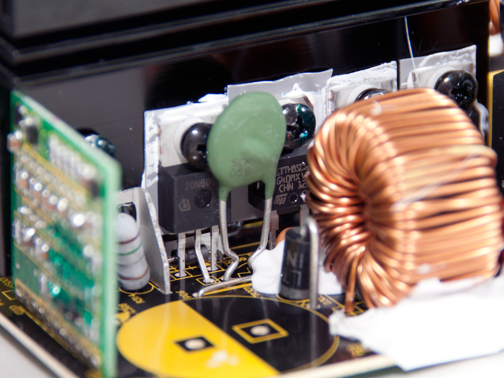
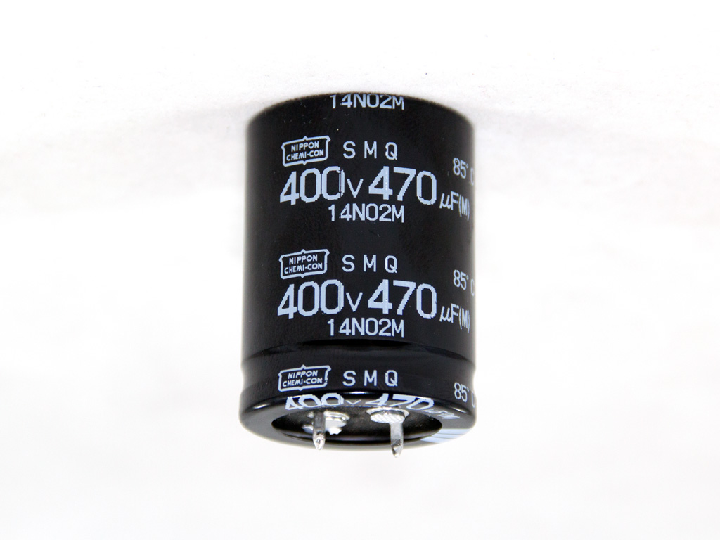
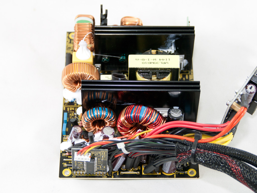
In the APFC two SPP20N60C3 fets separate the full-wave rectified DC voltage, coming from the bridge rectifier, into constant pulse sequences and as boost diode an STTH8S06D is used. The hold up cap is provided by Nippon Chemi-Con (470µF, 400V, 85°C, SMQ series).


The primary switches are two SPP20N60C3 fets and the combo PFC/PWM controller is an Infineon ICE1CS02. The latter is housed on a vertical daughter-board located in the primary side.

The standby PWM controller is a Fairchild Q0165R which supports valley switching. This reduces EMI emissions while efficiency increases.
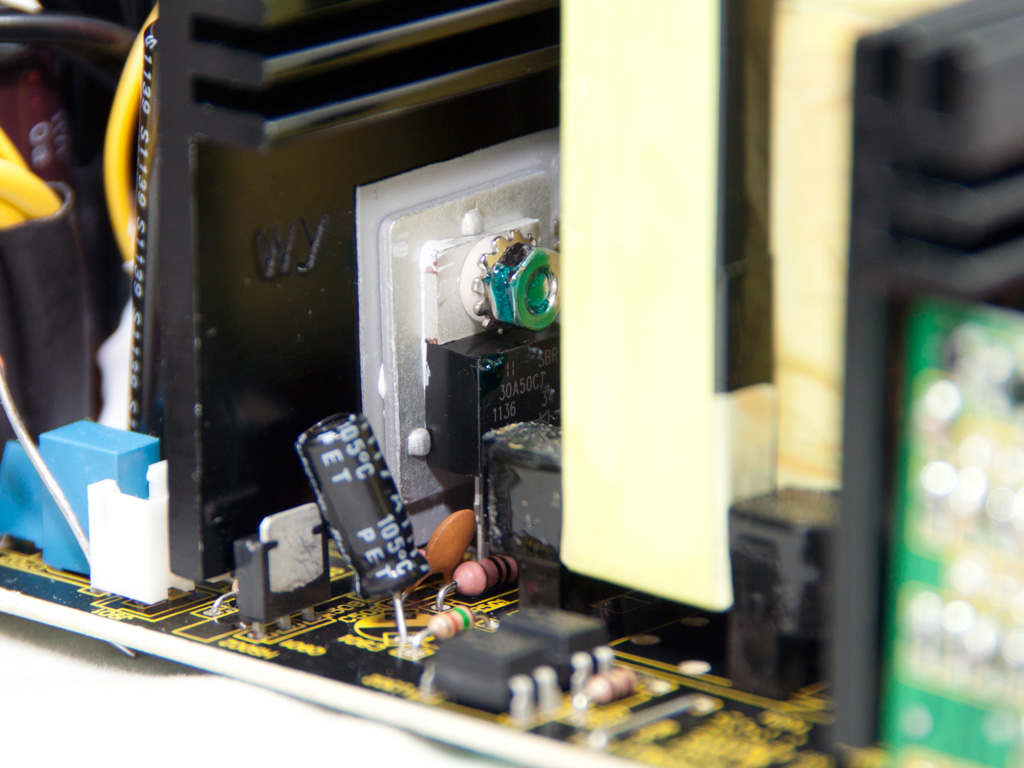


In the secondary side passive design is used, meaning that Schottky Barrier Rectifiers are used for the regulation of the rails (except -12V). The +12V rail handle two SBR30A50CT, one SBR40U45CT rectifies 5V and finally one PFR30L30CT rectifies 3.3V. The presence of only two toroidal chokes in the secondary side means that a group regulation design is used so the bigger choke is for 12V and 5V while the smaller one is used by 3.3V.

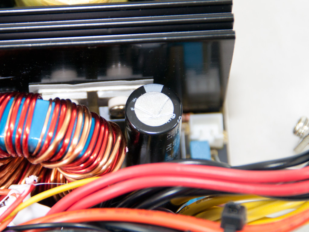
All filtering capacitors in the secondary side are Japanese and almost all are provided by Nippon Chemi-Con, but we also found a single Rubycon. All are rated at 105°C.

The supervisor IC is installed on a small vertical PCB in the secondary side. It is a SiTI PS223 and supports OCP for up to two +12V rails, however in this unit there is a single +12V rail so the second OCP channel is not needed.

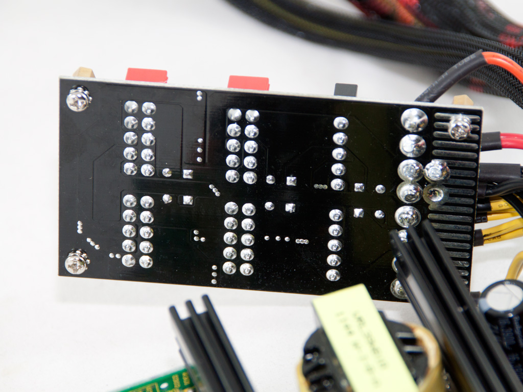
On the front of the modular PCB there are six Chemi-Con caps for some extra ripple filtering. On the rear, soldering quality is excellent.


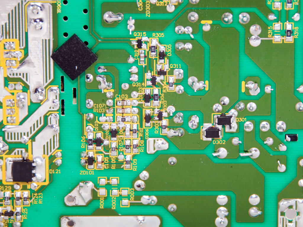

Soldering quality on the main PCB isn't that great, especially for a Seasonic product. We spotted several sloppy joints with excess use of solder and on top of that some component leads are rather long. Apparently quality control on these not high-end Seasonic units is not so tight. Finally, on the solder side of the main PCB the 5VSB rectifier is installed. It is an SBR10U45 which can handle up to 10A at 110ºC.

The cooling fan is provided by Adda and its model number is ADN512MB-A90 (12V, 0.27A). It has nine blades, is equipped with a plastic baffle to direct the airflow and at full speed it's quite noisy. Also at Adda's official site we couldn't find any info about this model since there was only the A91 model listed, which has lower energy consumption (0.2A) so most likely there will be other differences, too.
Apr 26th, 2024 14:37 EDT
change timezone
Latest GPU Drivers
New Forum Posts
- hacked (74)
- Best SSD for system drive (87)
- looking to build a new system and im considering asrock brand but i have some doubts/concerns. (0)
- What phone you use as your daily driver? And, a discussion of them. (1485)
- XFX RX470 8GB no video and error 43 (29)
- DTS:X APO4 + DTS Interactive for Most Devices [USB Supported] (305)
- The Official Linux/Unix Desktop Screenshots Megathread (702)
- What's your latest tech purchase? (20352)
- im new to throttelstop and i think i messed it up by copying others any hints would be very much aprreciated (5)
- 2022-X58/1366 PIN Motherboards NVME M.2 SSD BIOS MOD Collection (657)
Popular Reviews
- HYTE THICC Q60 240 mm AIO Review
- MOONDROP x Crinacle DUSK In-Ear Monitors Review - The Last 5%
- Alienware Pro Wireless Gaming Keyboard Review
- Upcoming Hardware Launches 2023 (Updated Feb 2024)
- Thermalright Phantom Spirit 120 EVO Review
- FiiO K19 Desktop DAC/Headphone Amplifier Review
- ASUS Radeon RX 7900 GRE TUF OC Review
- AMD Ryzen 7 7800X3D Review - The Best Gaming CPU
- RTX 4090 & 53 Games: Ryzen 7 5800X vs Ryzen 7 5800X3D Review
- NVIDIA RTX 4090: 450 W vs 600 W 12VHPWR - Is there any notable performance difference?
Controversial News Posts
- Windows 11 Now Officially Adware as Microsoft Embeds Ads in the Start Menu (129)
- Sony PlayStation 5 Pro Specifications Confirmed, Console Arrives Before Holidays (117)
- NVIDIA Points Intel Raptor Lake CPU Users to Get Help from Intel Amid System Instability Issues (106)
- AMD "Strix Halo" Zen 5 Mobile Processor Pictured: Chiplet-based, Uses 256-bit LPDDR5X (103)
- US Government Wants Nuclear Plants to Offload AI Data Center Expansion (98)
- AMD's RDNA 4 GPUs Could Stick with 18 Gbps GDDR6 Memory (93)
- Developers of Outpost Infinity Siege Recommend Underclocking i9-13900K and i9-14900K for Stability on Machines with RTX 4090 (85)
- Windows 10 Security Updates to Cost $61 After 2025, $427 by 2028 (84)