 13
13
Corsair GS800 V2 800 W Review
Voltage Regulation & Efficiency »A Look Inside
Before reading this page we strongly suggest to take a look at this article, which will help you understand the internal components of a PSU much better.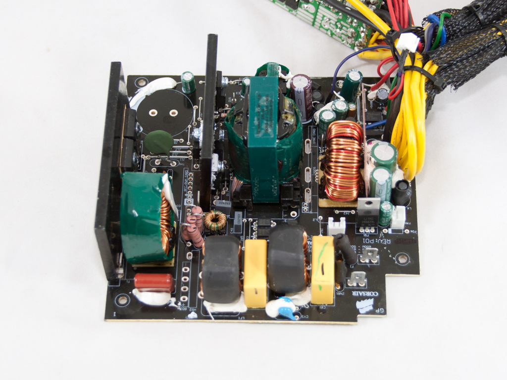

The revised GS800 has the same OEM as the older one, Channel Well Technology or CWT, a manufacturer that has close co-operation with Corsair. The platform is new, named PUQ and we have met it recently in the new Thermaltake SMART 750W we reviewed some weeks ago. It is a pretty modern design with synchronous rectification in the secondary side and VRMs for the minor rails generation; however in order to restrict production cost the PCB is single-sided.
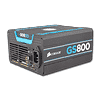
We removed many parts, in order to provide you the best possible view.

The transient or EMI filter starts right at the AC receptacle with two Y caps. Also the cables that transfer power to the main PCB are wrapped around a ferrite bead for EMI suppression. On the main PCB we find the remaining components of the transient filter, two pairs of X and Y caps, two CM chokes and an MOV. Also as you can see the power wires are connected through spade terminals, something that makes the removal of the main PCB a breeze.


The single bridge rectifier is sandwiched among two dedicated heatsinks with the second one being made from copper. Its model number is GBU1506 and it can handle up to 15A.


In the APFC two IPW60R190C6 fets are used along with the necessary boost diode. The single hold up cap (470μF, 400V, 105°C) is provided by Matsushita/Panasonic and the combo PFC/PWM controller is the famous Champion CM6800.

The thermistor responsible for protection against large inrush currents during start up, is installed before the hold up cap.

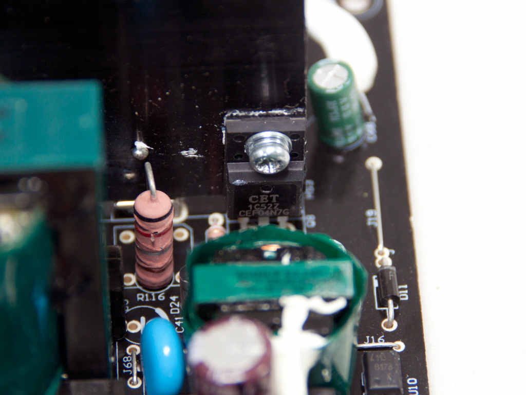
The main switchers are two Toshiba TK18A50D fets in double forward topology. On the same heatsink we also found a CEF04N7G fet which most likely is utilized by the 5VSB rectification circuit.

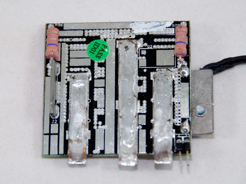
In the secondary side synchronous design is used and the +12V rail is regulated by six fets which are housed on a small vertical PCB. Strangely enough there is no heatsink attached to help in heat dissipation, but on the PCB's rear side three bus bars also help with heat removal, in addition to transferring power. Finally on this PCB there is a themistor, used by the fan control circuit.


All caps in the secondary side are provided by Teapo and rated at 105°C, except a single Nippon Chemi-Con which filters the 5VSB rail. The supervisor IC also resides in the secondary side and its model number is WT7502; it doesn't support OCP for +12V but has all other basic protections.


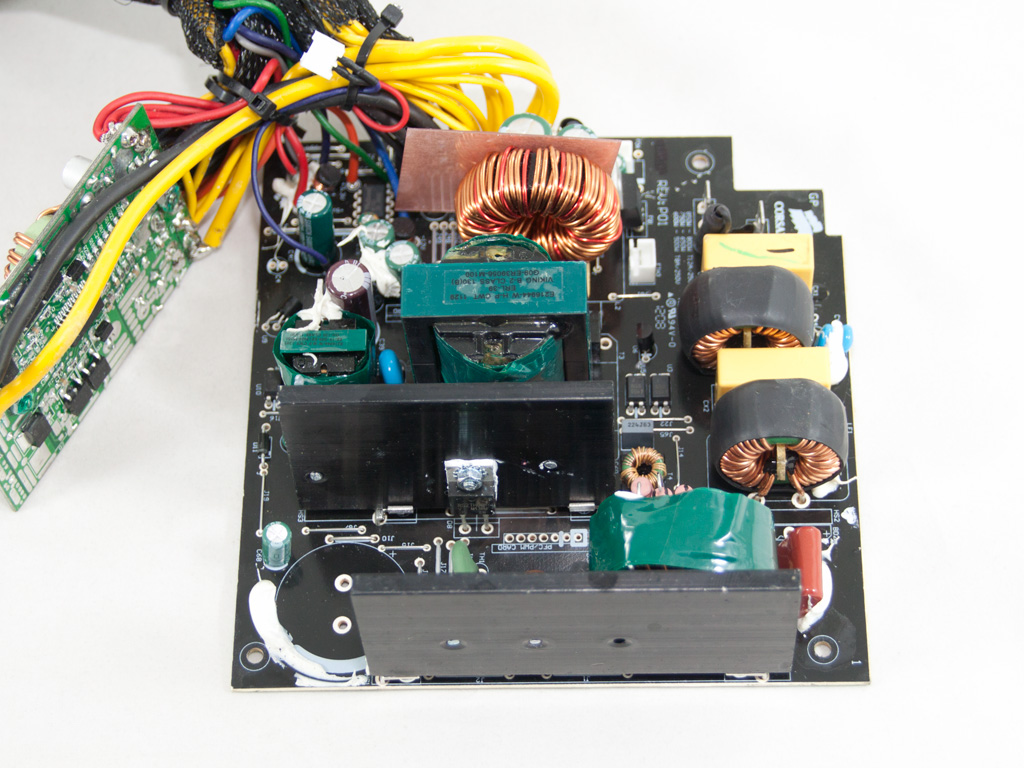
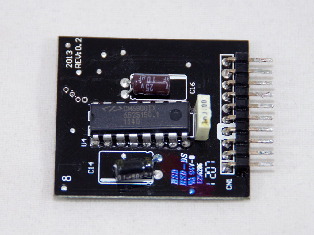
The VRMs that generate the minor rails are installed on a separate PCB which could easily house some modular sockets, too. The common buck PWM controller is an APW7159 IC and in each VRM three fets are used. Also soldering quality on this PCB is decent. On the front side we find several polymer caps provided by Enesol and another unknown brand (the blue ones).


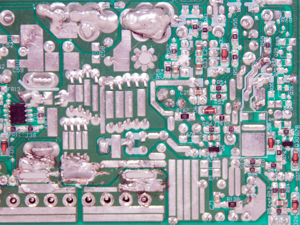

The main PCB doesn't feature top notch soldering quality, that's for sure, but not bad either. It's average, since we spotted enough blobby solder joints. Thankfully all component leads are carefully trimmed so we didn't find any long enough to cause trouble (short circuit). You can also see some damage, in the photo above, as our first sample didn't work properly. Corsair sent us a second one and it worked perfectly. I have tested this platform many times, so I am convinced this is not a design flaw or general issue.

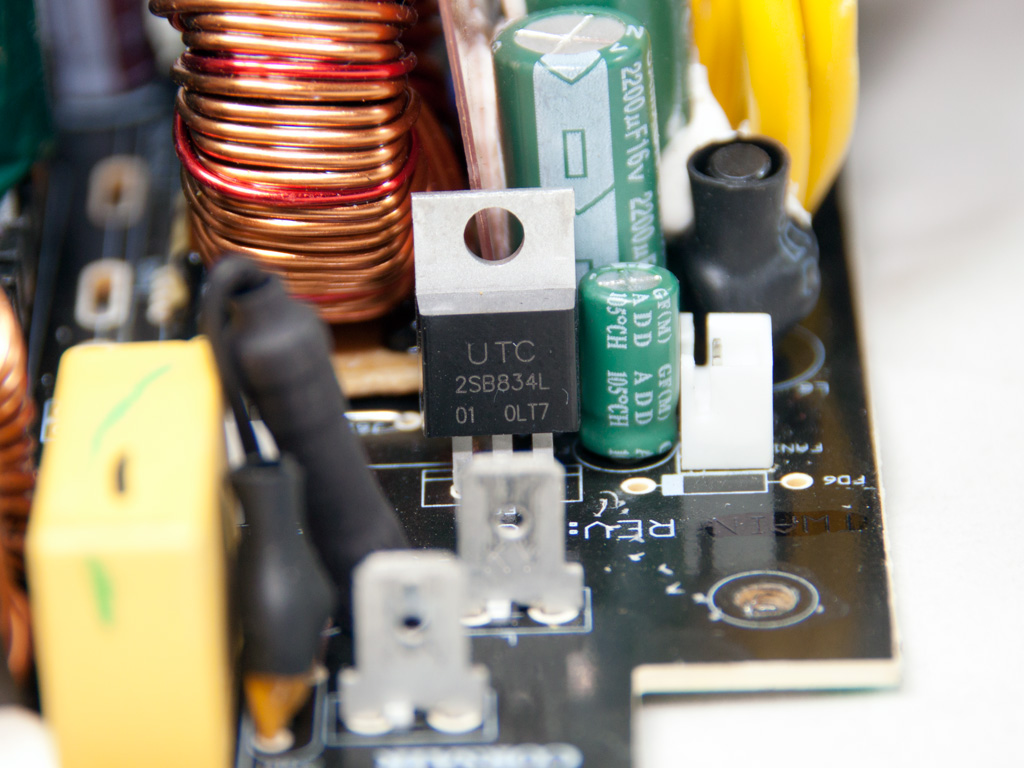
The cooling fan is provided by Hong Hua and its model number is HA1425H12B-Z (12V, 0.5A). It has double ball bearings and it is relative quiet thanks to the relaxed fan profile. A UTC2SB834L transistor is used to control its speed.
Apr 19th, 2024 16:44 EDT
change timezone
Latest GPU Drivers
New Forum Posts
- I7-8750H + GTX 1050ti Laptop drops performance periodically (4)
- Share your AIDA 64 cache and memory benchmark here (2883)
- AAF Optimus DCH Audio Modded Driver for Windows 10/11 - For ALL HDAUDIO Enumerator Chips (641)
- Linus watercools (52)
- Identify my GPU - RX 570 8GB (or what?) (7)
- Roccat Kone AIMO has developed a double left click, when I click it once. Any fix out there? (30)
- I9 13890HX undervolting Suggestions (3)
- [WIN11] 5700x3d Security processor Attestation: Not supported? (7)
- What are you playing? (20469)
- XFX RX560 1024 shaders 16 CU 4GB from Aliexpress (10)
Popular Reviews
- Horizon Forbidden West Performance Benchmark Review - 30 GPUs Tested
- PowerColor Radeon RX 7900 GRE Hellhound Review
- Fractal Design Terra Review
- Corsair 2000D Airflow Review
- Thermalright Phantom Spirit 120 EVO Review
- Minisforum EliteMini UM780 XTX (AMD Ryzen 7 7840HS) Review
- Creative Pebble X Plus Review
- FiiO KB3 HiFi Mechanical Keyboard Review - Integrated DAC/Amp!
- ASUS GeForce RTX 4090 STRIX OC Review
- NVIDIA GeForce RTX 4090 Founders Edition Review - Impressive Performance
Controversial News Posts
- Sony PlayStation 5 Pro Specifications Confirmed, Console Arrives Before Holidays (110)
- NVIDIA Points Intel Raptor Lake CPU Users to Get Help from Intel Amid System Instability Issues (102)
- US Government Wants Nuclear Plants to Offload AI Data Center Expansion (98)
- Windows 10 Security Updates to Cost $61 After 2025, $427 by 2028 (82)
- Developers of Outpost Infinity Siege Recommend Underclocking i9-13900K and i9-14900K for Stability on Machines with RTX 4090 (82)
- AMD "Strix Halo" Zen 5 Mobile Processor Pictured: Chiplet-based, Uses 256-bit LPDDR5X (78)
- TechPowerUp Hiring: Reviewers Wanted for Motherboards, Laptops, Gaming Handhelds and Prebuilt Desktops (72)
- Intel Realizes the Only Way to Save x86 is to Democratize it, Reopens x86 IP Licensing (70)