 8
8
Corsair TX750M 750 W Review
Voltage Regulation & Efficiency »A Look Inside
Before reading this page we strongly suggest to take a look at this article, which will help you understand the internal components of a PSU much better.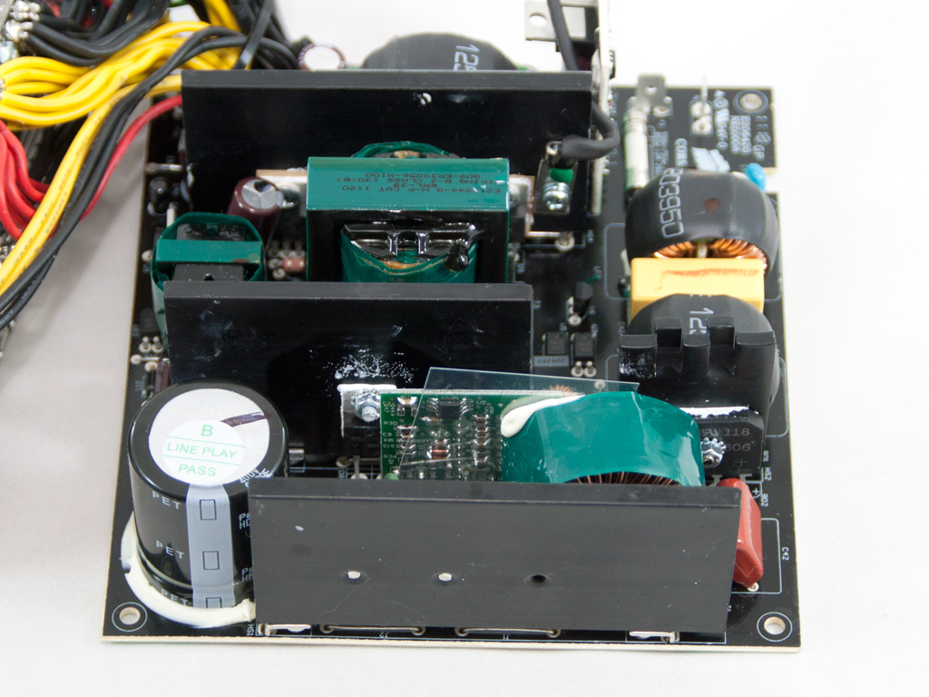


For the TX M series Corsair chose Channel Well Technology (CWT). As it seems Seasonic could not provide a modular version of the TX V2 Series, or the cost was too high. This is not bad of course since CWT is a highly respected manufacturer, which provided Corsair with many great platforms so far, including the first TX PSUs.
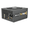
The transient filtering stage starts at the AC receptacle with two Y and one X caps. The latter has the standard bleeding resistor to discharge fast, since X caps tend to store energy for quite long. The transient filter continues at the main PCB with two more Y caps, one X, two coils and an MOV. All in all the transient filtering stage is complete.


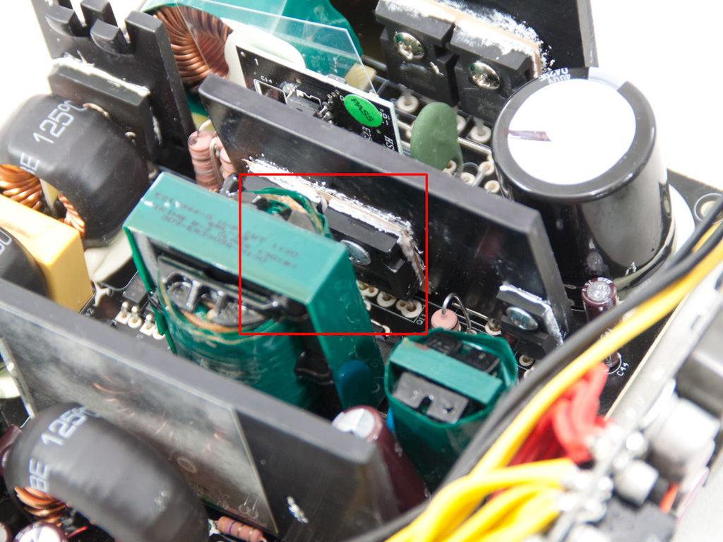

The two bridge rectifiers (GBU 606) are bolted on a heatsink. Afterwards, in the APFC, two SPW20N60C3 mosfets are used along with a boost diode. The smoothing/reservoir capacitor is provided by Panasonic (470μF, 400V, 105°C). In the primary heatsink we find two G20N50C mosfets as primary switches and another one mosfet (HFS3N80). The combo PFC/PWM controller is the omnipresent CM6800 IC and is housed on a daughter-board between the APFC and the primary heatsinks. Right behind the above mentioned daughter-board resides the thermistor responsible for inrush current protection. Unfortunately there is no relay to bypass it once the PSU starts leading to a small efficiency loss. On top of that some time is needed for the thermistor to cool down, after the PSU is switched off, in order to raise its resistance again and offer adequate protection.
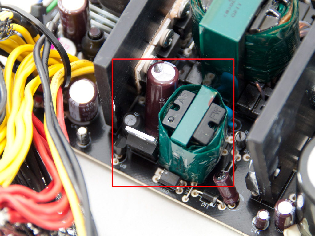
An SBL1040CTP is used for the 5VSB generation along with a small transformer and a Nippon Chemi-Con capacitor.


In the secondary, passive design is used so Schottky Barrier Rectifiers generate +12V. In total five SBR40U60CT are used. Here we should note that in the solder side of the main PCB and in the secondary side area we spotted an AP72T03GH mosfet which is probably used for the +12V regulation. If this stands then the design is semi-synchronous and not solely passive.
Afterwards a part of the +12V rail feeds the modular panel where the Voltage Regulation Modules (VRMs) that generate the minor rails reside. In total eight AP72T03GH mosfets are used in the two VRMs and the common PWM controller is an APW7159. As you can see from the photos above, the solder side of the modular PCB is densely populated. Finally, all capacitors used in the secondary side are provided by Nippon Chemi-Con and on the main PCB besides electrolytics we also found a polymer one. On the modular PCB, where the VRMs are located, only polymer caps are used along with two sealed coils.


Housekeeping duties are handled by a PS113. This IC does not support OCP and if we take into account that we did not find any shunt resistors on the main PCB we can safely assume that this unit does not have OCP (Over Current Protection). However this protection is not necessary in a 750W single rail PSU and Over Power Protection (OPP), which is not listed in TX750M characteristics, or Under Voltage Protection (UVP) will intervene if something goes wrong.

Soldering quality is good enough, not top notch though since we found some sloppy solder joints. However we did not see any long component leads and this pleased us the most.

Responsible for cooling down the unit is a Yate Loon double ball bearing fan with model number D14BH-12 (12V, 0.7A, 2800RPM, 140CFM, 48.5dBA).
Apr 25th, 2024 15:59 EDT
change timezone
Latest GPU Drivers
New Forum Posts
- What are you playing? (20528)
- What software are you using to monitor CPU temps during gaming session? (11)
- What phone you use as your daily driver? And, a discussion of them. (1480)
- Black screen after muting (4)
- Alphacool CORE 1 CPU block - bulging with danger of splitting? (14)
- Will a RTX 4070 TI super bottleneck a Ryzen 9 7950X3D? (59)
- How to check flatness of CPUs and coolers - INK and OPTICAL INTERFERENCE methods (111)
- Ghetto Mods (4321)
- Random blue screen from winload.efi error (0xc000000e) (2)
- Meta Horizon OS (20)
Popular Reviews
- Fractal Design Terra Review
- Thermalright Phantom Spirit 120 EVO Review
- Corsair 2000D Airflow Review
- Minisforum EliteMini UM780 XTX (AMD Ryzen 7 7840HS) Review
- ASUS GeForce RTX 4090 STRIX OC Review
- NVIDIA GeForce RTX 4090 Founders Edition Review - Impressive Performance
- ASUS GeForce RTX 4090 Matrix Platinum Review - The RTX 4090 Ti
- MSI GeForce RTX 4090 Suprim X Review
- MSI GeForce RTX 4090 Gaming X Trio Review
- Gigabyte GeForce RTX 4090 Gaming OC Review
Controversial News Posts
- Sony PlayStation 5 Pro Specifications Confirmed, Console Arrives Before Holidays (116)
- NVIDIA Points Intel Raptor Lake CPU Users to Get Help from Intel Amid System Instability Issues (106)
- Windows 11 Now Officially Adware as Microsoft Embeds Ads in the Start Menu (103)
- AMD "Strix Halo" Zen 5 Mobile Processor Pictured: Chiplet-based, Uses 256-bit LPDDR5X (101)
- US Government Wants Nuclear Plants to Offload AI Data Center Expansion (98)
- AMD's RDNA 4 GPUs Could Stick with 18 Gbps GDDR6 Memory (86)
- Developers of Outpost Infinity Siege Recommend Underclocking i9-13900K and i9-14900K for Stability on Machines with RTX 4090 (85)
- Windows 10 Security Updates to Cost $61 After 2025, $427 by 2028 (84)