 21
21
EVGA SuperNOVA NEX750G 750 W Review
Voltage Regulation, Hold-up Time & Inrush Current »A Look Inside & Component Analysis
Before reading this page, we strongly suggest a look at this article, which will help you understand the internal components of a PSU much better.
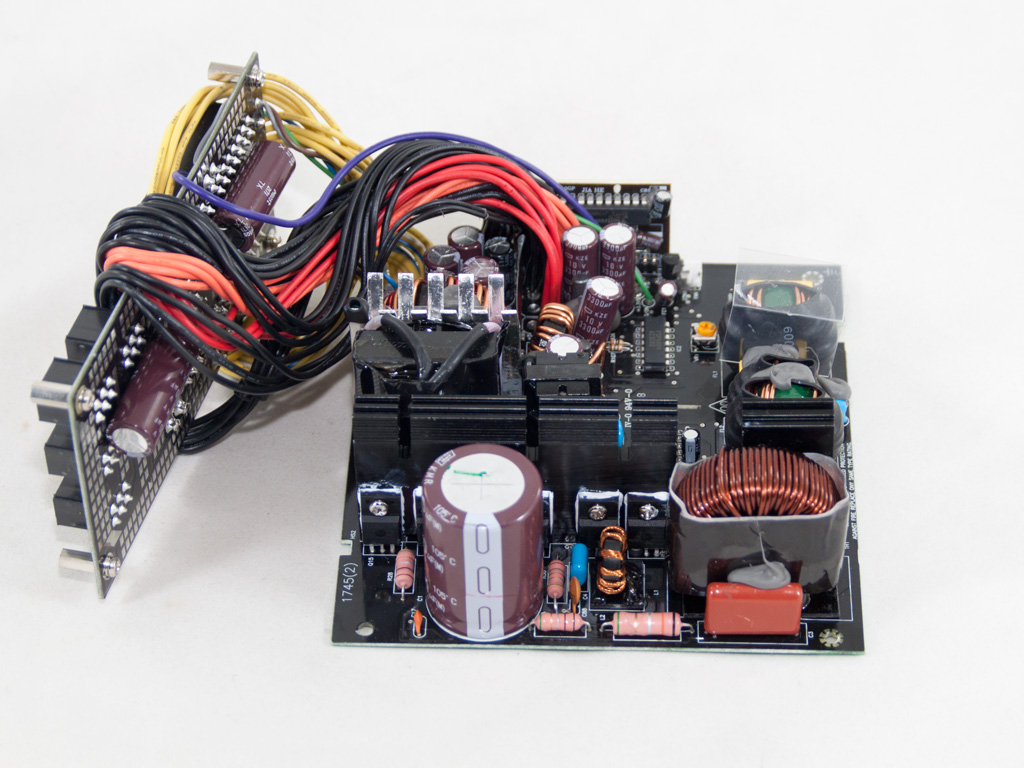


EVGA trusted FSP with their smaller SuperNova units, and they, to be more specific, utilized their Aurum platform. Definitely not the platform we would use for a PSU that belongs to a high-end series and one that has to compete with pretty advanced opponents, since the Aurum platform, although it combines low production cost with high efficiency, exhibits low performance in situations where the load on the rails is highly unbalanced (e.g. in our crossload tests). On the primary side, we meet an Active Clamp Reset Forward (ACRF) topology in which two mosfets are used: one plays the role of the main switcher (Q1) and the other is the reset switch (Q2) that disconnects the main capacitor(s) while Q1 is active.

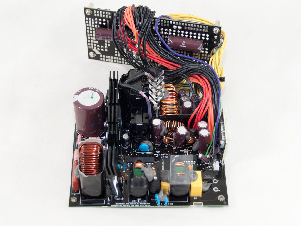
At the AC receptacle, we find the first part of the transient filtering stage, which only consists of two Y caps. We find the other parts, two CM and one DM chokes and two pairs of X and Y caps, on the main PCB. The design doesn't include an MOV (Metal Oxide Varistor), something that we don't approve of. However, FSP claims that the MIA IC that this platform uses offers over-voltage protection and that it can absorb excess surges coming from the power grid. Still, we would highly prefer it if they utilized an MOV as well. On the solder side of this area, we found a CAP004DG discharge IC that blocks current through the X caps discharge resistors when AC voltage is connected and automatically discharges X caps through the aforementioned resistors when AC is disconnected. This procedure leads to increased efficiency since no energy is wasted on resistors. Finally, a micro-fuse is used instead of a regular-sized fuse.

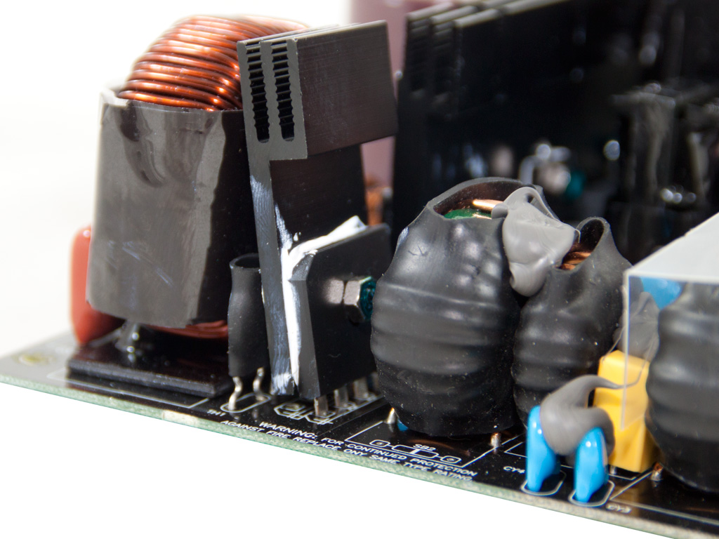
The single bridge rectifier is bolted onto a dedicated, leaning heatsink.

The thermistor that provides protection against large inrush currents and the diode that bypasses it once the PSU starts are located between the bridge diode's heatsink and the APFC choke.
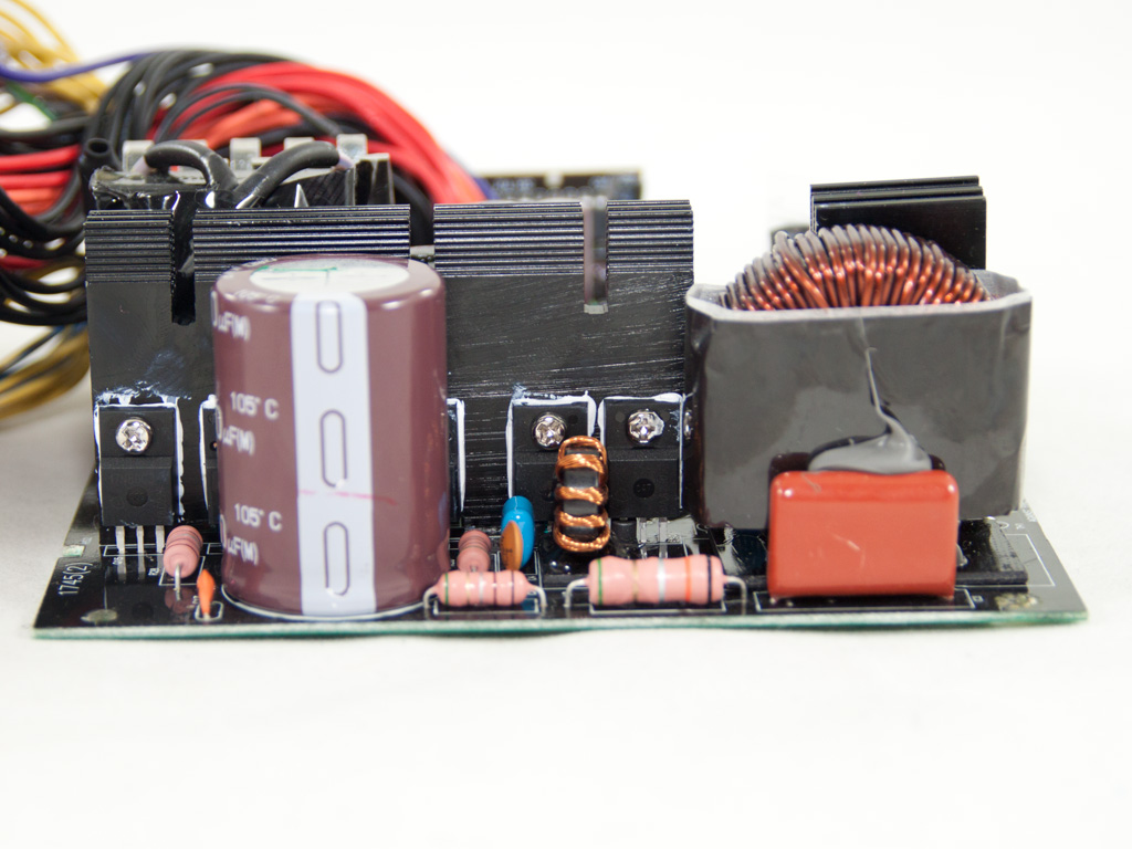

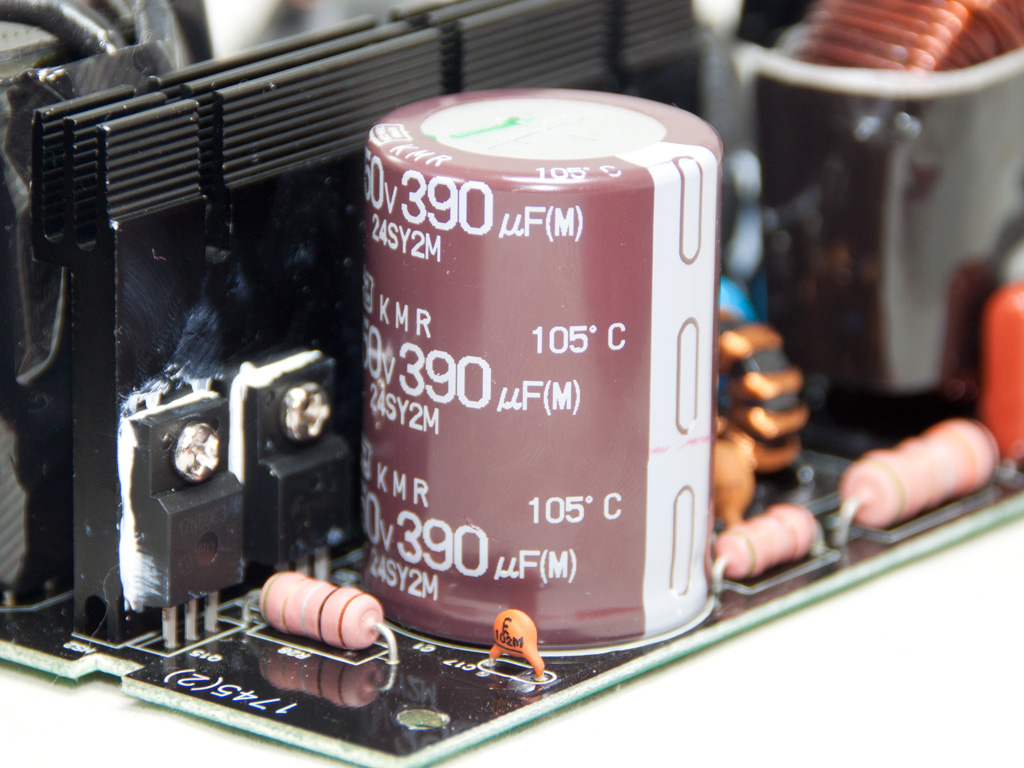
In the APFC, two Infineon IPA60R165CP fets are used along with the necessary boost diode. Right behind the boost diode, also attached onto the primary heatsink, is the 5VSB regulation mosfet, a GE03N70T that supports up to 3.3A continuous drain current at 25°C and only 2.1A continuous drain current at 100°C. This means that it will operate very close to its limit with a full load at 5VSB. The hold-up cap is provided by Nippon Chemi-Con (450 V, 390 μF, 105°C, KMR series), and it manages to provide excellent hold-up time, although it looks small.
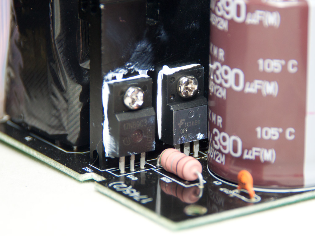
In the ACRF topology, which we briefly explained at the top of this page, the role of the Q1 fet is played by a SPA17N80C3, and we find a FQPF3N80C fet taking over the role of the Q2 fet. The APFC/PWM controller is the FSP 6600 IC for which there is no public documentation available.
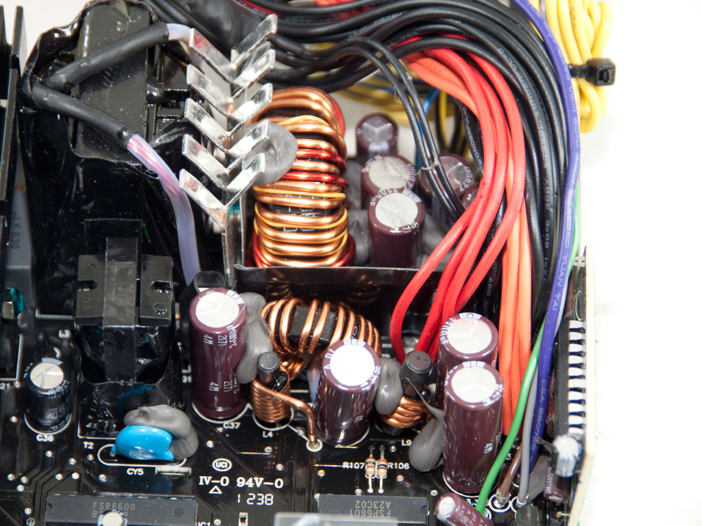

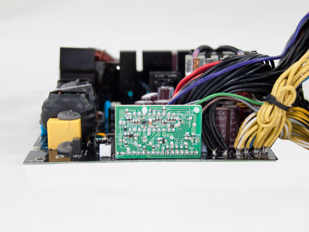
A synchronous design is used on the secondary side, and two mosfets that are cooled by a small heatsink handle the generation of +12V. The 5V rail is most likely regulated along with the +12V rail and two IPD050N03L output it. Finally, the 3.3V rail is generated by the 5V rail through a DC-DC converter and the help of two IPD031N03L fets. So a group-regulated scheme is utilized for the generation of the rails, something that will negatively affect performance on crossload tests.

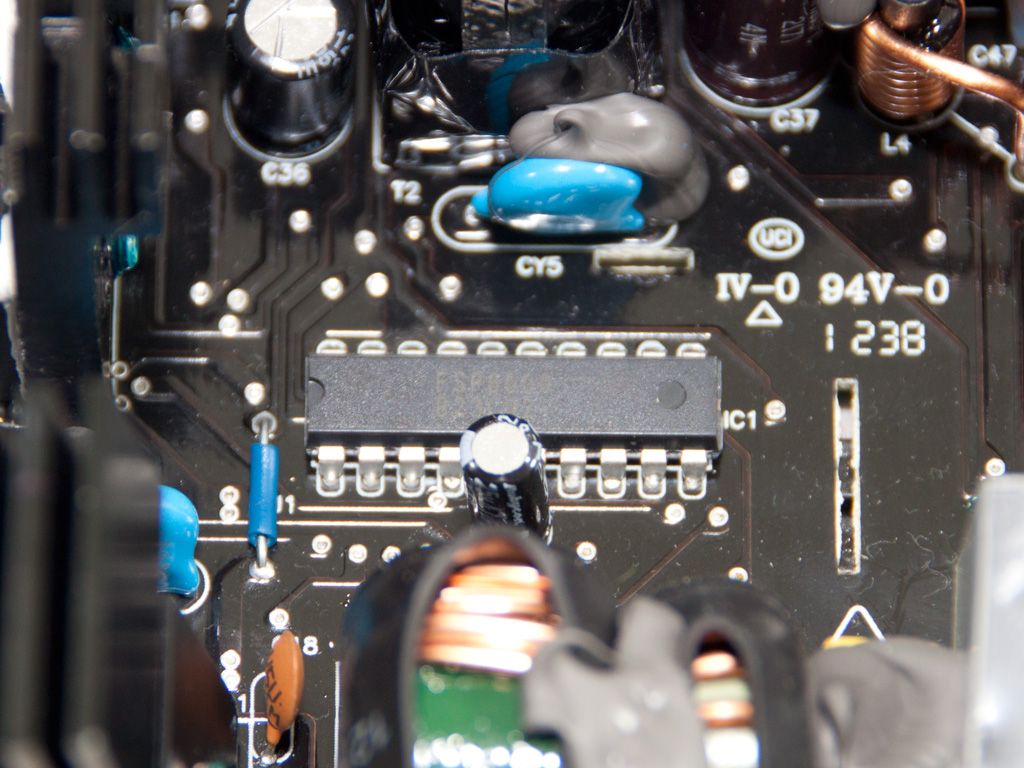
The PWM controller responsible for the secondary side is the proprietary FSP 6601 IC, and all filtering caps are provided by Nippon Chemi-Con. They are rated at 105°C.

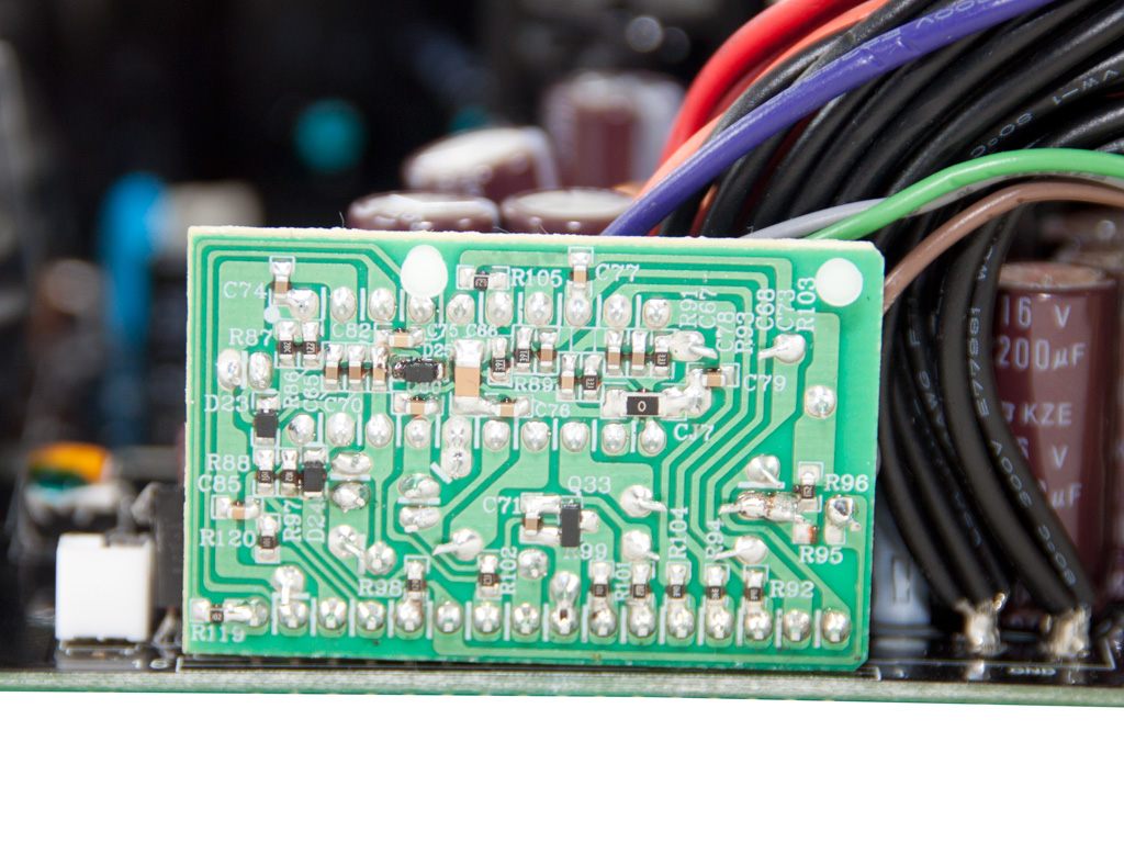
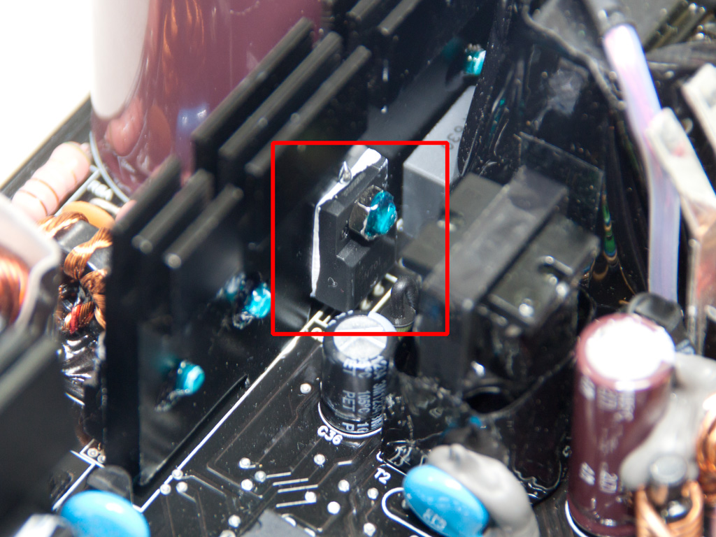
Housekeeping is done by a Weltrend WT7579 supervisor IC for which we didn't find any documentation online.
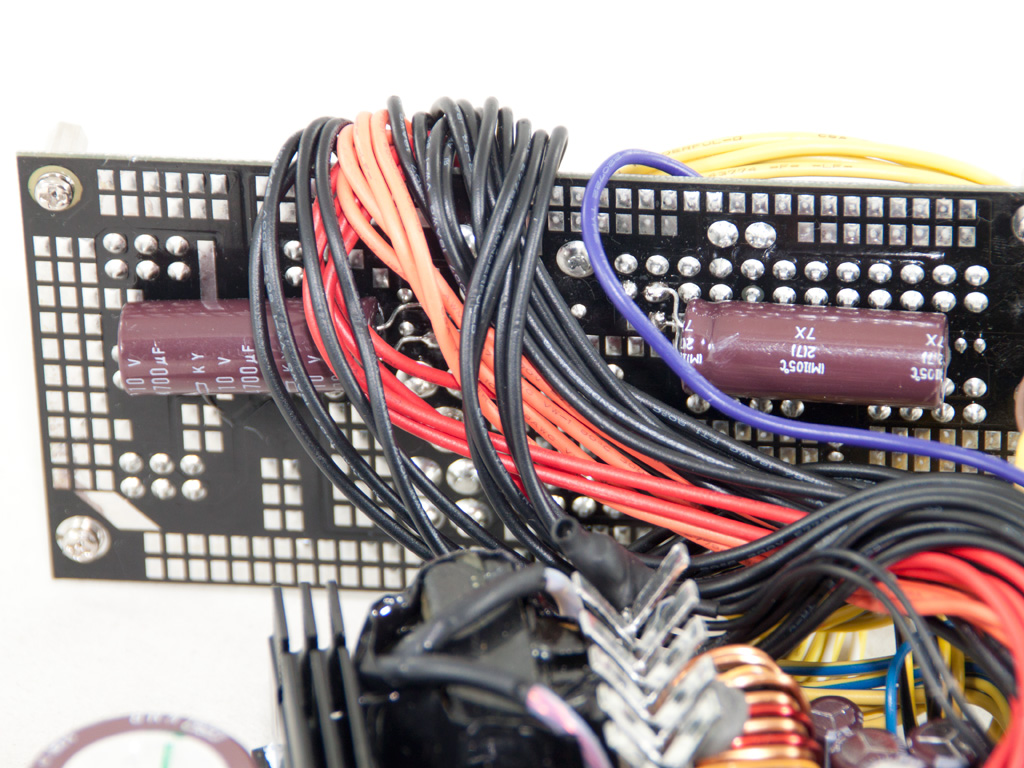


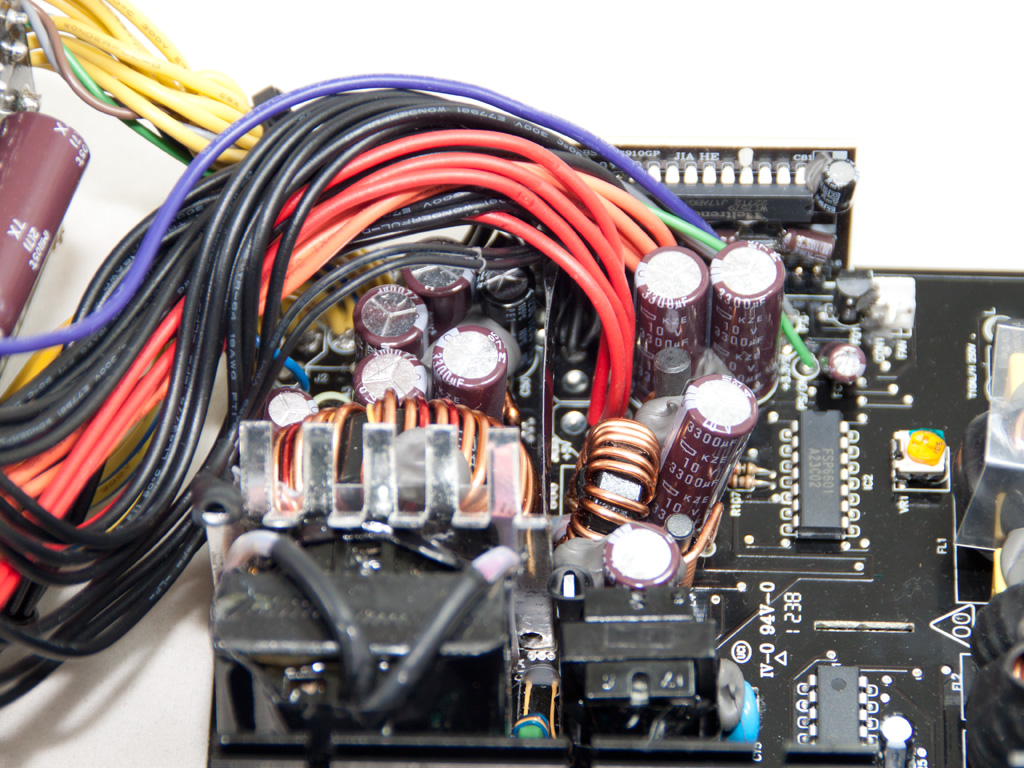
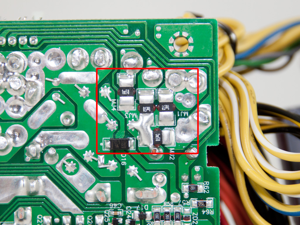
On the solder side of the modular PVB, two large Chemi-Con caps (KY series, 105°C) are used for extra ripple filtering. At the front, we also found four small Chemi-Con polymer caps that are used for ripple filtering.

Some heat-shrink tubing around these wires would be nice!
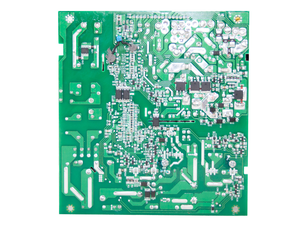

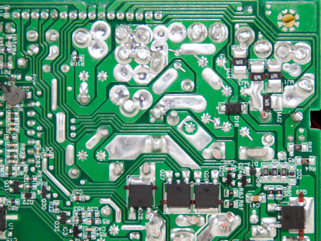


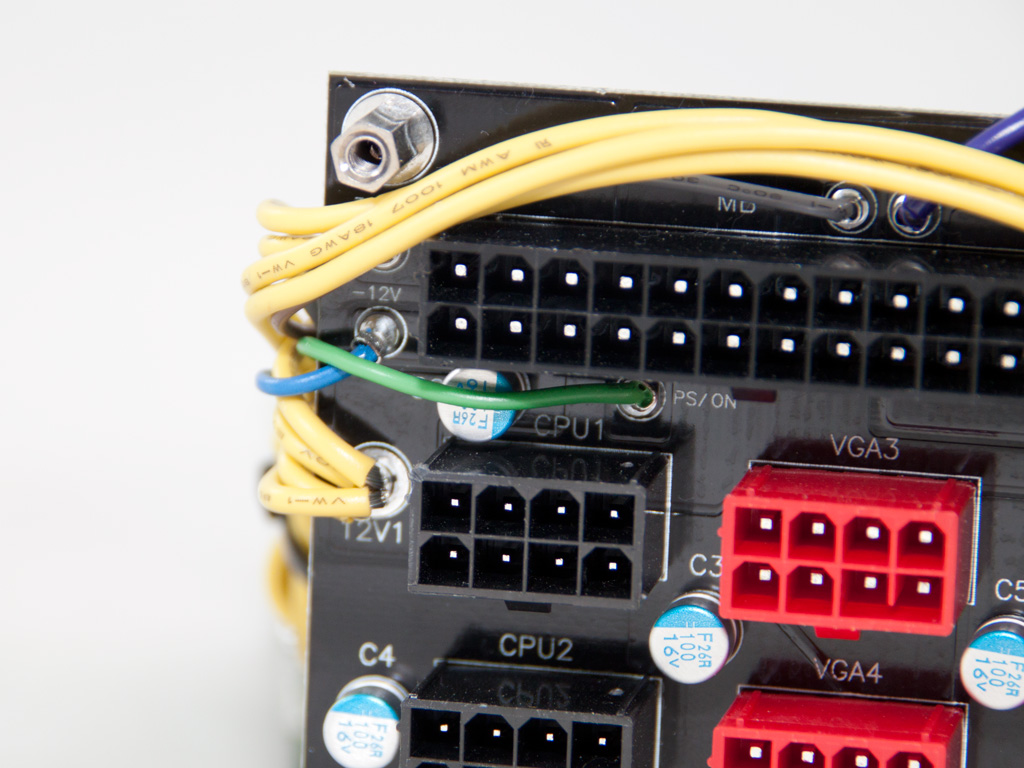
Soldering quality on the main PCB is good enough, although we spotted a last minute modification. Four shunt resistors under the +12V islands provide enough proof to back up the official specification of four +12V rails.


The fan is provided by Yate Loon Electronics and it's the classic D14BH-12 model (140 mm, 12 V, 0.7 A, 2800 RPM, 140 CFM, 48.5 dBA) that is quite strong and noisy at high RPM.
Apr 26th, 2024 08:20 EDT
change timezone
Latest GPU Drivers
New Forum Posts
- GoDeal24 Windows 11 Pro 32-bit! (1)
- What's your latest tech purchase? (20348)
- What are you playing? (20537)
- Alphacool CORE 1 CPU block - bulging with danger of splitting? (24)
- Old high quality PSU, or semi-old mid-quality PSU? (1)
- Horizontal black lines popping up on my screen? (10)
- Best SSD for system drive (86)
- The Official Linux/Unix Desktop Screenshots Megathread (695)
- Share your AIDA 64 cache and memory benchmark here (2918)
- Secure boot already open help (1)
Popular Reviews
- HYTE THICC Q60 240 mm AIO Review
- MOONDROP x Crinacle DUSK In-Ear Monitors Review - The Last 5%
- Alienware Pro Wireless Gaming Keyboard Review
- Upcoming Hardware Launches 2023 (Updated Feb 2024)
- Thermalright Phantom Spirit 120 EVO Review
- ASUS Radeon RX 7900 GRE TUF OC Review
- RTX 4090 & 53 Games: Ryzen 7 5800X vs Ryzen 7 5800X3D Review
- FiiO K19 Desktop DAC/Headphone Amplifier Review
- NVIDIA RTX 4090: 450 W vs 600 W 12VHPWR - Is there any notable performance difference?
- RTX 4090 & 53 Games: Core i9-13900K vs Ryzen 7 5800X3D Review
Controversial News Posts
- Windows 11 Now Officially Adware as Microsoft Embeds Ads in the Start Menu (123)
- Sony PlayStation 5 Pro Specifications Confirmed, Console Arrives Before Holidays (117)
- NVIDIA Points Intel Raptor Lake CPU Users to Get Help from Intel Amid System Instability Issues (106)
- AMD "Strix Halo" Zen 5 Mobile Processor Pictured: Chiplet-based, Uses 256-bit LPDDR5X (101)
- US Government Wants Nuclear Plants to Offload AI Data Center Expansion (98)
- AMD's RDNA 4 GPUs Could Stick with 18 Gbps GDDR6 Memory (89)
- Developers of Outpost Infinity Siege Recommend Underclocking i9-13900K and i9-14900K for Stability on Machines with RTX 4090 (85)
- Windows 10 Security Updates to Cost $61 After 2025, $427 by 2028 (84)