 21
21
EVGA SuperNOVA NEX750G 750 W Review
Ripple Measurements »Advanced Transient Response Tests
In these tests, we monitor the response of the PSU in two different scenarios. First, a transient load (10 A at +12V, 5 A at 5V, 5 A at 3.3V, and 0.5 A at 5VSB) is applied to the PSU for 200 ms while the latter is working in a 20% load state. In the second scenario, the PSU, while working at 50% load, is hit by the same transient load. In both tests, we measure the voltage drops that the transient load causes using our oscilloscope. The voltages should remain within the regulation limits defined by the ATX specification. We must stress here that the above tests are crucial since they simulate transient loads that a PSU is very likely to handle (e.g., booting a RAID array, an instant 100% load of CPU/VGAs, etc.) We call these tests "Advanced Transient Response Tests", and they are designed to be very tough to master, especially for PSUs with capacities lower than 500 W.| Advanced Transient Response 20% | ||||
|---|---|---|---|---|
| Voltage | Before | After | Change | Pass/Fail |
| 12 V | 12.022V | 11.858V | 1.36% | Pass |
| 5 V | 5.019V | 4.914V | 2.09% | Pass |
| 3.3 V | 3.268V | 3.144V | 3.79% | Pass |
| 5VSB | 4.938V | 4.886V | 1.05% | Pass |
| Advanced Transient Response 50% | ||||
|---|---|---|---|---|
| Voltage | Before | After | Change | Pass/Fail |
| 12 V | 11.904V | 11.756V | 1.24% | Pass |
| 5 V | 4.998V | 4.925V | 1.46% | Pass |
| 3.3 V | 3.234V | 3.097V | 4.24% | Fail |
| 5VSB | 4.881V | 4.825V | 1.15% | Pass |
Deviations are, except on the 3.3V rail, low on all rails, but a loose voltage regulation drops the voltage on all rails during the application of the transient load at low loads; that is, except for the 5V rail. Also, the extra loose voltage regulation on the 3.3V rail, along with the high deviation that it registers with the application of the transient load, led to a big fail on the second test with the voltage dropping below 3.1 V. Something else we noticed off the scope shots was the significant time the 12V and 5V rails need to stabilize their voltages as compared to other units we have tested in the past. The ACRF topology is most likely responsible for such a long stabilization time. It primarily affects the +12V rail, which in turn causes such a problem on the 5V rail that is generated through a DC-DC converter by the +12V rail. Strangely enough, the 3.3V rail isn't affected.
Below, you will find the oscilloscope screenshots that we took during Advanced Transient Response Testing.
Transient Response at 20% Load


Transient Response at 50% Load


Turn-On Transient Tests
We measure the response of the PSU in simpler scenarios of transient loads - during the power-on phase of the PSU - in the next set of tests. In the first test, we turn the PSU off, dial the maximum current that the 5VSB can output, and then switch on the PSU. In the second test, we dial the maximum load that +12V can handle and we start the PSU, all while the PSU is in standby mode. In the last test, while the PSU is completely switched off (we cut off power or switch off the PSU's on/off switch), we dial the maximum load that the +12V rail can handle before switching the PSU on from the loader and restoring power. The ATX specification states that recorded spikes on all rails should not exceed 10% of their nominal values (e.g., +10% for 12V is 13.2V and for 5V is 5.5V).

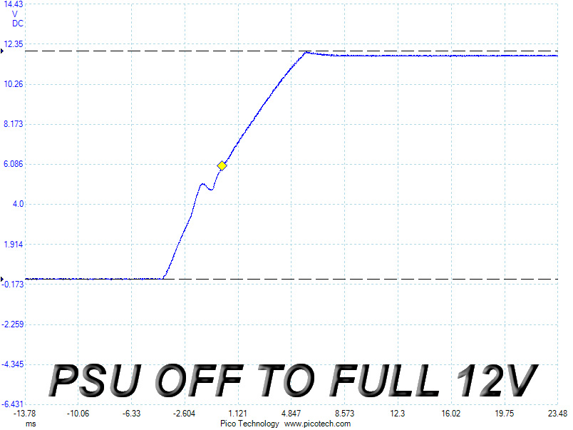
The 5VSB rail registered a small spike which is, however, below the nominal voltage of this rail. At +12V, we measured two spikes with the second one (standby to full test) being the higher by reaching almost 12.5 V, a fairly high reading that is still well below the 13.2 V limit.
May 6th, 2024 12:07 EDT
change timezone
Latest GPU Drivers
New Forum Posts
- Overheating/undervolt/setup issues (7)
- Battery swap for cyberpower UPS (59)
- Only some humans can see refresh rates faster than others, I am one of those humans. (177)
- What is this? (3)
- The Official Thermal Interface Material thread (1163)
- Apparently Valve is giving refunds on Helldivers 2 regardless of hour count. Details inside. (95)
- Strange system crashes out of nowhere, help (29)
- How to check flatness of CPUs and coolers - INK and OPTICAL INTERFERENCE methods (116)
- Envinda RX 580 2048SP 8GB no image (18)
- Is this Sapphire PULSE RX 5600 XT legit or fake? (41)
Popular Reviews
- Finalmouse UltralightX Review
- ASRock NUC BOX-155H (Intel Core Ultra 7 155H) Review
- Meze Audio LIRIC 2nd Generation Closed-Back Headphones Review
- Cougar Hotrod Royal Gaming Chair Review
- Upcoming Hardware Launches 2023 (Updated Feb 2024)
- Montech Sky Two GX Review
- AMD Ryzen 7 7800X3D Review - The Best Gaming CPU
- HYTE THICC Q60 240 mm AIO Review
- ASUS Radeon RX 7900 GRE TUF OC Review
- Logitech G Pro X Superlight 2 Review - Updated with 4000 Hz Tested
Controversial News Posts
- Intel Statement on Stability Issues: "Motherboard Makers to Blame" (248)
- Windows 11 Now Officially Adware as Microsoft Embeds Ads in the Start Menu (167)
- AMD to Redesign Ray Tracing Hardware on RDNA 4 (165)
- Sony PlayStation 5 Pro Specifications Confirmed, Console Arrives Before Holidays (117)
- AMD's RDNA 4 GPUs Could Stick with 18 Gbps GDDR6 Memory (114)
- NVIDIA Points Intel Raptor Lake CPU Users to Get Help from Intel Amid System Instability Issues (106)
- AMD Ryzen 9 7900X3D Now at a Mouth-watering $329 (104)
- AMD "Strix Halo" Zen 5 Mobile Processor Pictured: Chiplet-based, Uses 256-bit LPDDR5X (103)