 0
0
OCZ Fatal1ty 550 W Review
Voltage Regulation, Hold-up Time & Inrush Current »A Look Inside & Component Analysis
Before reading this page, we strongly suggest a look at this article, which will help you understand the internal components of a PSU much better. Our main tool for the disassembly of the PSU is a Thermaltronics TMT-9000S soldering and rework station. It is of extreme quality and is equipped with a matching de-soldering gun. With such equipment in hand, breaking apart every PSU is like a walk in the park!
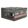
We recently saw this platform in our NZXT HALE82 V2 700 W review, and its performance failed to impress us. It is by Sirtec, a manufacturer of budget-oriented units, not cutting-edge and expensive ones. Su'scon caps, which are of mediocre quality, are then used everywhere, and the design is outdated as passive components rectify the rails in the secondary side and a group regulated scheme is utilized. We are pretty sure performance in crossload tests will suck big time.
The transient filter usually starts at the AC receptacle with one X and two Y caps. We spotted a CMD02X on the X cap. It restricts energy losses on the bleeding resistor. The second part of the transient filter is on the main PCB and includes two CM chokes, one X cap, two Y caps, and an MOV that has been installed behind the bridge rectifier. We really don't understand why the MOV has been instaled after the bridge rectifier since it leaves the latter exposed to power surges.

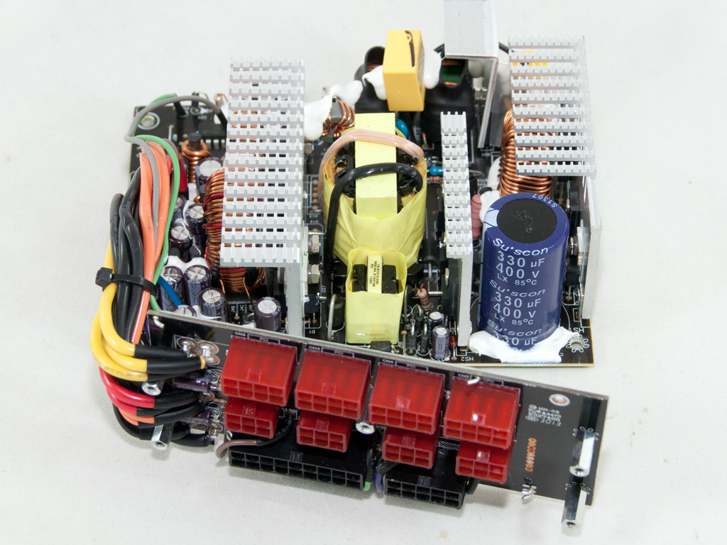
The single bridge rectifier is bolted to a small, dedicated heatsink. The small MOV is installed right in front of it.
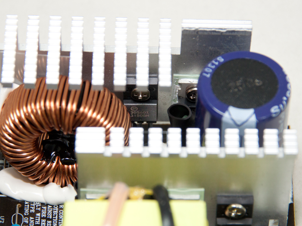
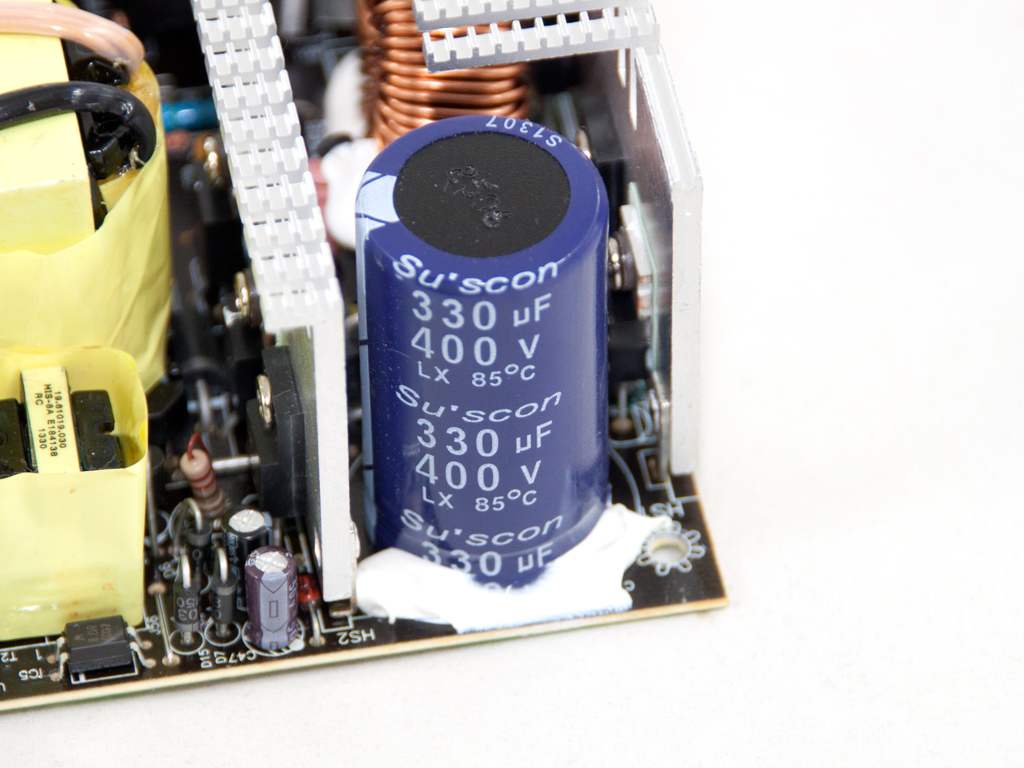
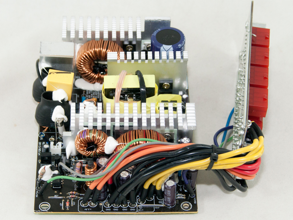
In the APFC converter, two AP20S60I fets and a single BYC10-600 boost diode are used. The bulk cap is provided by Su'scon (330 μF, 400 V, 85C, LX series) and is not only of incredibly low quality, but also low capacity. The prerogative was obviously to save a couple bucks by using the most affordable cap around.

Two Magnachip MDP18N50 fets are used as main switchers. The same heatsink that holds the above fets also hosts the SBR that rectifies the 5VSB rail, a UTC 2N60L.


Budget restrictions dictate the use of a group regulated scheme in the secondary side, where the 12V and 5V rails use the same voltage regulating circuit and the same toroidal choke, while the 3.3V rail uses the smaller toroidal choke and is generated by a magamp post regulator. Only having two chokes in the secondary side is usually a clear indication of a group regulated design, and the main disadvantage of the latter as compared to independent regulation on all rails is the mediocre performance with highly unbalanced loads on all rails.
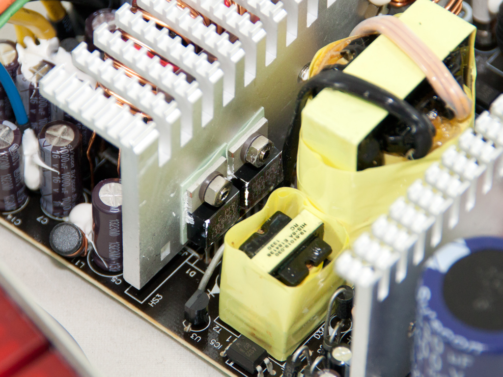

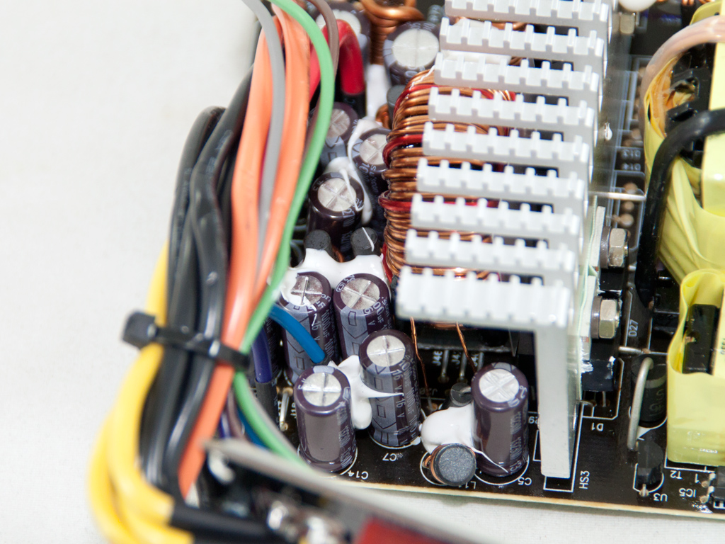
Four PFR30L60CT SBRs (Schottky Barrier Diodes) rectify the +12V rail, while the minor rails are generated by two Mospec S30D45C SBRs. All filtering caps in the secondary side are also provided by Su'scon. We would definitely like better caps here.


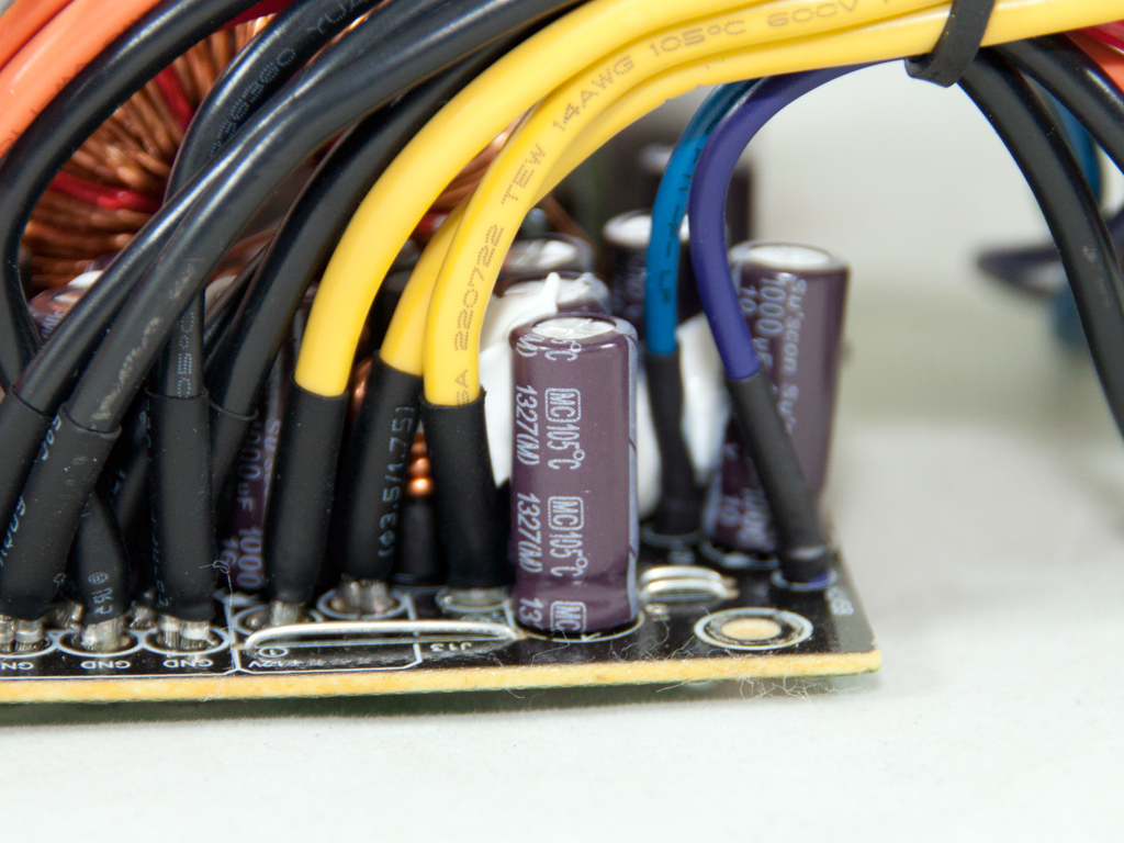
Two small Su'scon caps on the front of the modular PCB provide some extra ripple filtering, and soldering quality on the obverse side isn't so good.

The protections IC, a Sitronix ST95313, is soldered directly to the main PCB, and we didn't find any information about it on the net. Taking into account its small size and the unit's specifications, it must only provide the very basic protection features.


Soldering quality on the rear side of the main PCB is of acceptable quality.

We found a CM6803 IC, the combo PFC/Standby controller, and a CM03X Green PFC controller on the solder side of the PCB.

The fan is provided by Globefan, and its model number is RL4Z S1352512H (12 V, 0.33 A, 106.86 CFM, 29.2 dBA, 1500 RPM). It uses a plain sleeve bearing and belongs to the budget/mainstream category, like the PSU it equips.
May 10th, 2024 20:10 EDT
change timezone
Latest GPU Drivers
New Forum Posts
- 2024 and STILL no dark mode? (2)
- Flash VBIOS to turn RX 580 2048SP into RX 570 (35)
- What are you playing? (20618)
- Going from a 2070 to a 4070 ti super, should i uninstall drivers first? (14)
- AM5 boot times improve RADICALLY with memory context restore enabled (34)
- The Official Thermal Interface Material thread (1181)
- I don't think Ryzen 9900x3d is just being announced next month, I think it's launching next month. (26)
- Intel Core Ultra 9 185H - PROCHOT (3)
- 6800XT Red Devil with 18°C difference from Core to Hotspot (13)
- Soundblaster x-ae5 plus sometimes switches center channel to other channels. (4)
Popular Reviews
- Bykski CPU-XPR-C-I CPU Water Block Review - Amazing Value!
- CHERRY XTRFY M64 Pro Review
- ThundeRobot ML903 NearLink Review
- Corsair MP700 Pro SE 4 TB Review
- ZMF Caldera Closed Planar Magnetic Headphones Review
- Corsair iCUE Link RX120 RGB 120 mm Fan Review
- Upcoming Hardware Launches 2023 (Updated Feb 2024)
- AMD Ryzen 7 7800X3D Review - The Best Gaming CPU
- Finalmouse UltralightX Review
- ASUS Radeon RX 7900 GRE TUF OC Review
Controversial News Posts
- Intel Statement on Stability Issues: "Motherboard Makers to Blame" (264)
- AMD to Redesign Ray Tracing Hardware on RDNA 4 (206)
- Windows 11 Now Officially Adware as Microsoft Embeds Ads in the Start Menu (170)
- NVIDIA to Only Launch the Flagship GeForce RTX 5090 in 2024, Rest of the Series in 2025 (144)
- Sony PlayStation 5 Pro Specifications Confirmed, Console Arrives Before Holidays (119)
- AMD's RDNA 4 GPUs Could Stick with 18 Gbps GDDR6 Memory (114)
- NVIDIA Points Intel Raptor Lake CPU Users to Get Help from Intel Amid System Instability Issues (106)
- AMD Ryzen 9 7900X3D Now at a Mouth-watering $329 (104)