 7
7
Seasonic X-460FL 460 W Review
Voltage Regulation & Efficiency »A Look Inside
Before reading this page we strongly suggest to take a look at this article, which will help you understand the internal components of a PSU much better.
Seasonic used gold colored and pretty small heatsinks in X-460FL, although it is a fanless PSU. Gold efficiency PSUs have very low energy dissipation thus they manage to keep their operating temperatures low.


The AC receptacle incorporates a Delta line filter which houses one X and two Y capacitors and two coils. In the main PCB there are more components of the transient/EMI filtering stage, two coils, one X and two Y capacitors and an MOV. There is also a thermistor for inrush current protection and an electromagnetic relay that bypasses it once its job is finished. In the upper right corner of the relay resides the awkwardly soldered standby Quasi-Resonant PWM Controller, an ICE2QR4765.


After the transient filter we find two powerful GBJ1506 bridge rectifiers. Way overspec for the merely 460W of the PSU. In the APFC three mosfets (SPP24N60C3) and a STPSC806D boost diode are used. The smoothing/reservoir capacitor is provided by Nippon Chemi-Con and is rated at 105°C, 420V, 390μF. The APFC is controlled by an NC1564 IC and the LLC resonant controller is a CM6901. This controller operates the primary switches in PWM mode at light loads and in FM mode at higher loads. Finally two 26NM60N are the primary switches.


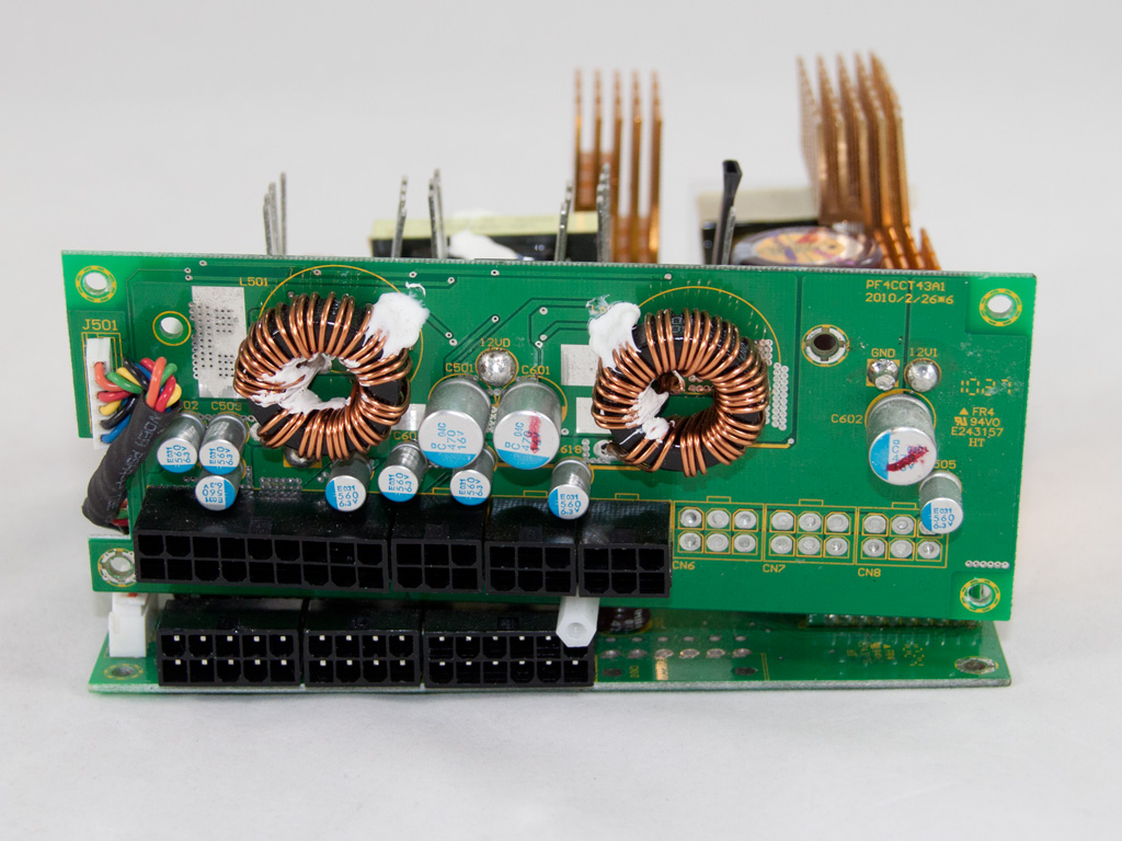

In the secondary side synchronous design is utilized and the four mosfets (IPD031N06L) that regulate +12V are located on the solder side of the main PCB. Although we comment on soldering quality later, in a separate paragraph, we should note here that there are some ugly soldering jobs around these mosfets. Continuing the secondary description, the afore-mentioned mosfets are cooled passively by the casing through a thermal pad and also three heatsinks on the other side of the main PCB are helping. The minor rails are generated through two VRMs (Voltage Regulation Modules or DC-DC converters) that are located on the modular panel, for minimized energy losses. The main PWM controller of the two VRMs is an APW7159 and for each output there are four IPD060N03L mosfets. In the secondary side a few electrolytic and many polymer capacitors are used to filter the DC outputs. Almost all are provided from Nippon Chemi Con since we found several Rubycons (e.g. 5VSB filtering is handled by a Rubycon cap).


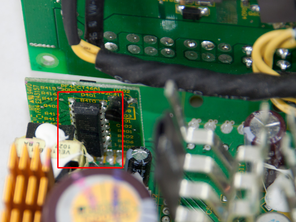
The protection ICs are located on a separate daughter-board at an edge of the main PCB, a PS223 and an LM393 voltage comparator.

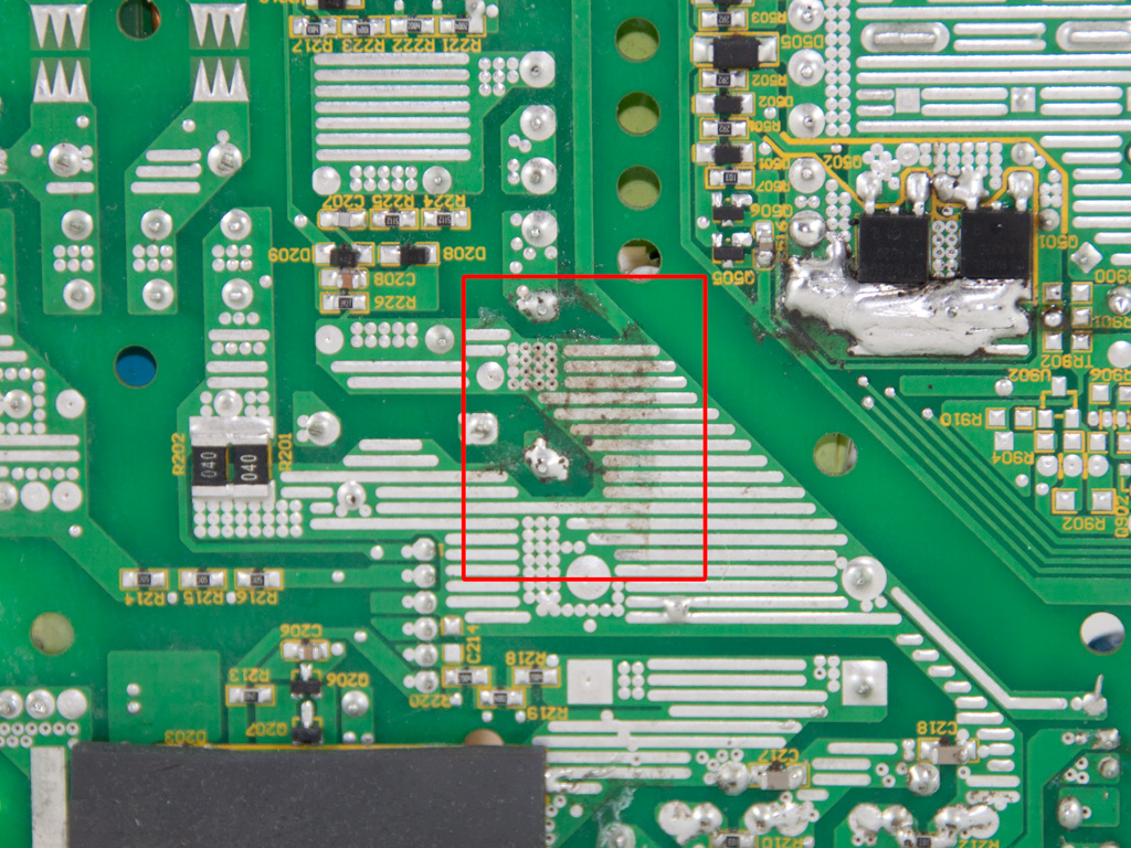
Soldering quality on the main PCB was above average but didn't reach the quality levels we expected from a Seasonic product. We found two sloppy hand made solder joints around +12V mosfets and the PCB was dirty possible from soldering flux at some places.
Apr 24th, 2024 02:42 EDT
change timezone
Latest GPU Drivers
New Forum Posts
- Official Board Game Discussion (13)
- The TPU UK Clubhouse (24772)
- Random blue screen from winload.efi error (0xc000000e) (0)
- What's your latest tech purchase? (20327)
- Which new games will you be buying? (304)
- need help with motherboard/ ram compability certainty (15)
- Flashing lenovo BIOS (11)
- FINAL FANTASY XIV: Dawntrail Official Benchmark (72)
- What phone you use as your daily driver? And, a discussion of them. (1455)
- I am getting artifacting when I change Windows security settings. Is my GPU failing, or is this just a Windows issue? (9)
Popular Reviews
- Fractal Design Terra Review
- Corsair 2000D Airflow Review
- Thermalright Phantom Spirit 120 EVO Review
- Minisforum EliteMini UM780 XTX (AMD Ryzen 7 7840HS) Review
- ASUS GeForce RTX 4090 STRIX OC Review
- NVIDIA GeForce RTX 4090 Founders Edition Review - Impressive Performance
- ASUS GeForce RTX 4090 Matrix Platinum Review - The RTX 4090 Ti
- MSI GeForce RTX 4090 Suprim X Review
- MSI GeForce RTX 4090 Gaming X Trio Review
- Gigabyte GeForce RTX 4090 Gaming OC Review
Controversial News Posts
- Sony PlayStation 5 Pro Specifications Confirmed, Console Arrives Before Holidays (116)
- NVIDIA Points Intel Raptor Lake CPU Users to Get Help from Intel Amid System Instability Issues (106)
- AMD "Strix Halo" Zen 5 Mobile Processor Pictured: Chiplet-based, Uses 256-bit LPDDR5X (101)
- US Government Wants Nuclear Plants to Offload AI Data Center Expansion (98)
- Windows 10 Security Updates to Cost $61 After 2025, $427 by 2028 (84)
- Developers of Outpost Infinity Siege Recommend Underclocking i9-13900K and i9-14900K for Stability on Machines with RTX 4090 (84)
- TechPowerUp Hiring: Reviewers Wanted for Motherboards, Laptops, Gaming Handhelds and Prebuilt Desktops (77)
- Intel Realizes the Only Way to Save x86 is to Democratize it, Reopens x86 IP Licensing (70)