 6
6
be quiet! Power Zone 1000 W Review
Voltage Regulation, Hold-up Time & Inrush Current »A Look Inside & Component Analysis
Before reading this page, we strongly suggest a look at this article, which will help you understand the internal components of a PSU much better. Our main tool for the disassembly of the PSU is a Thermaltronics TMT-9000S soldering and rework station. It is of extreme quality and is equipped with a matching de-soldering gun. Breaking apart every PSU with such equipment in hand is a walk in the park!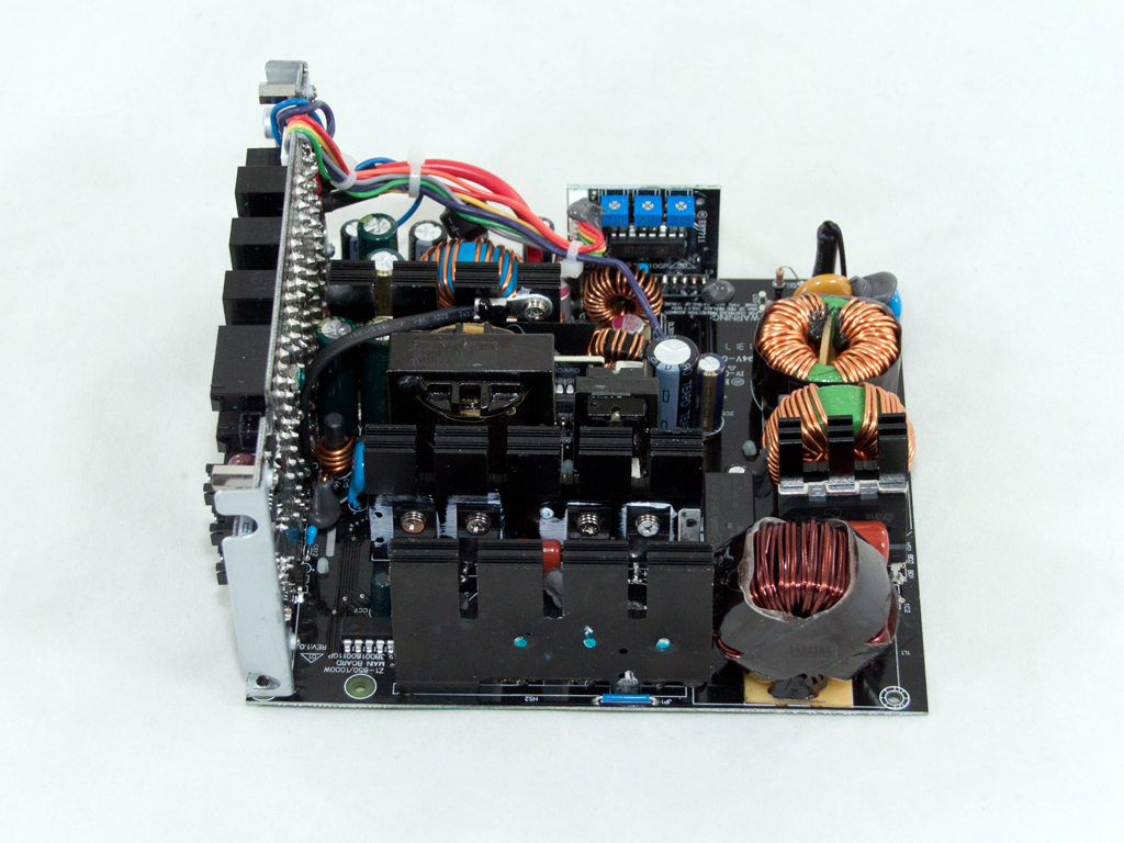

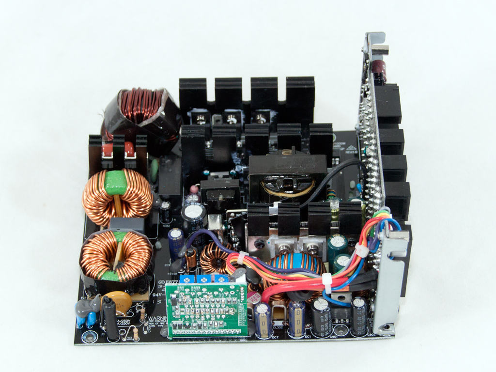

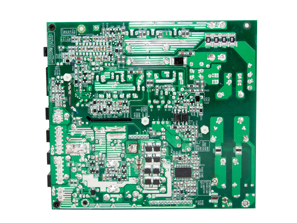
FSP, be quiet!'s favorite OEM, manufactures the Power Zone 1000 W using a two power switch Active Clamp Reset Forward (ACRF) topology in the primary side, which can easily achieve much higher efficiency than the unit's official Bronze certification. To give you an idea of the capabilities of this topology, both the Cooler Master Silent Pro Hybrid 1050 W and Silverstone Strider Gold Evolution 1000 W, Gold-certified units, use it. The secondary side uses a typical setup for modern PSUs: A synchronous design and DC-DC converters for the generation of the minor rails.
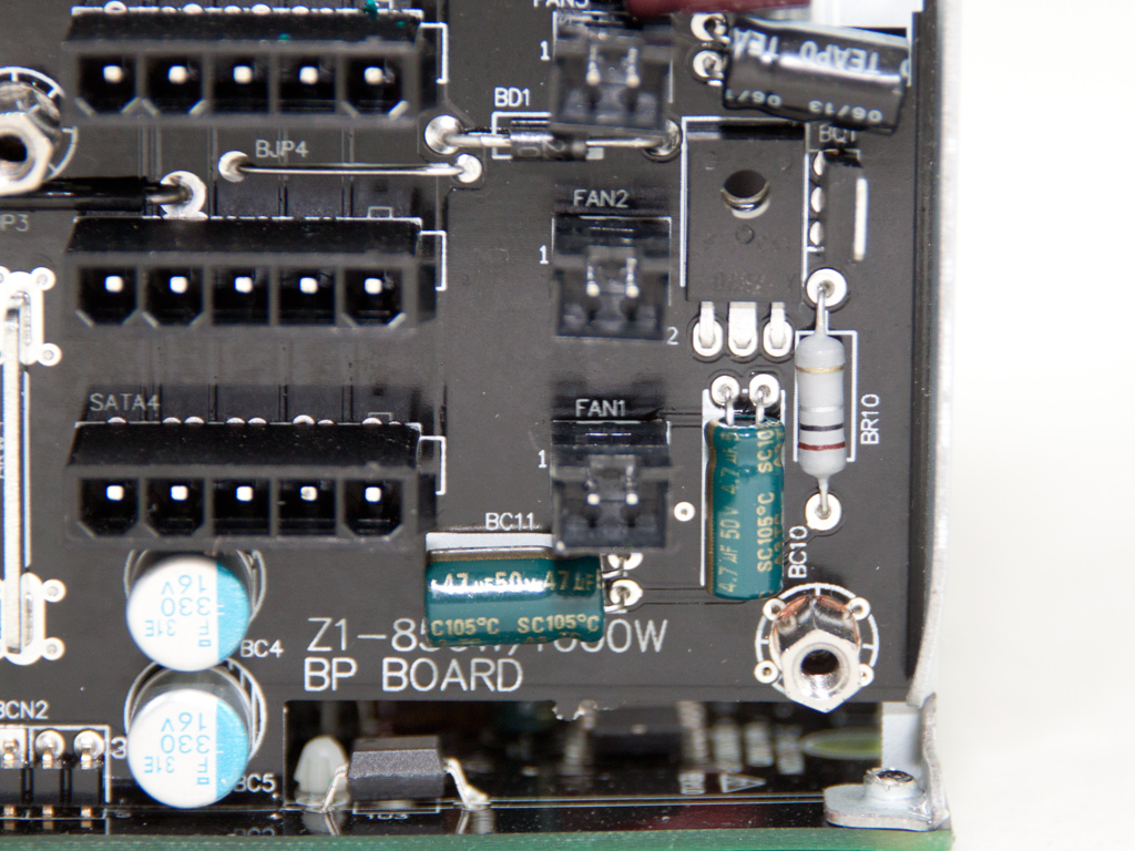
The first part of the transient filter starts right at the AC receptacle and includes a single X and a pair of Y caps. It continues on the main PCB with two CM chokes, an X and two Y caps, and an MOV.
The NTC thermistor protects against large inrush currents. An electromagnetic relay isolates it from the circuit once the start-up phase finishes to give it time to cool down and regain its nominal resistance, which also ensures that no energy is wasted on it during the PSU's normal operation.
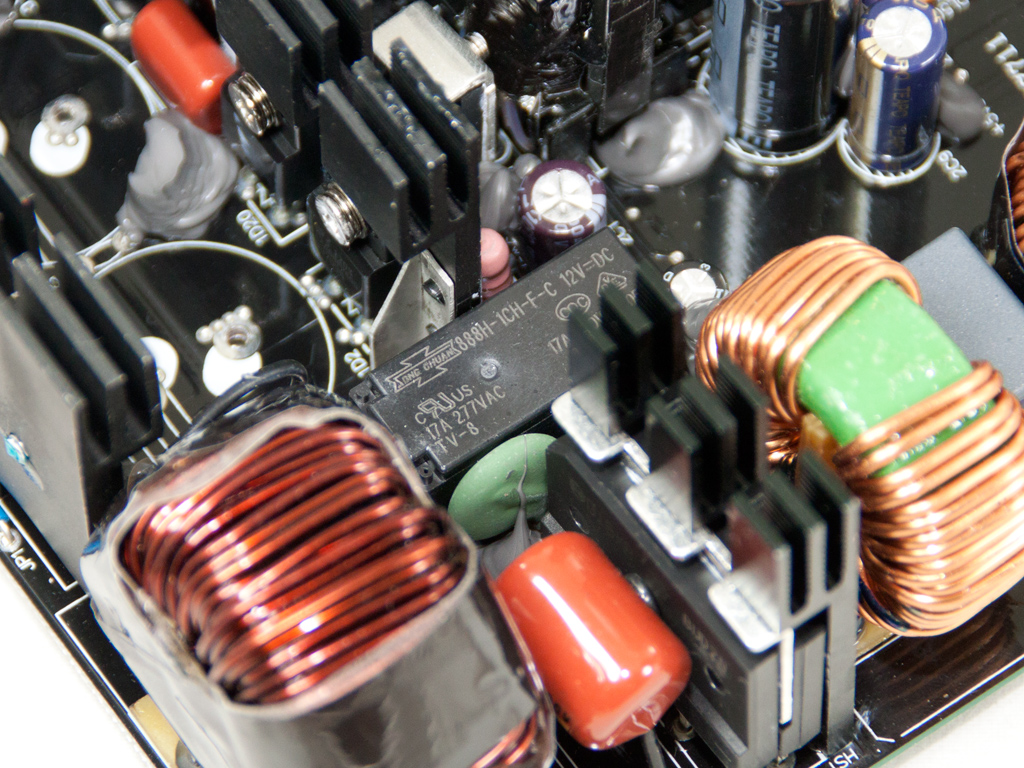
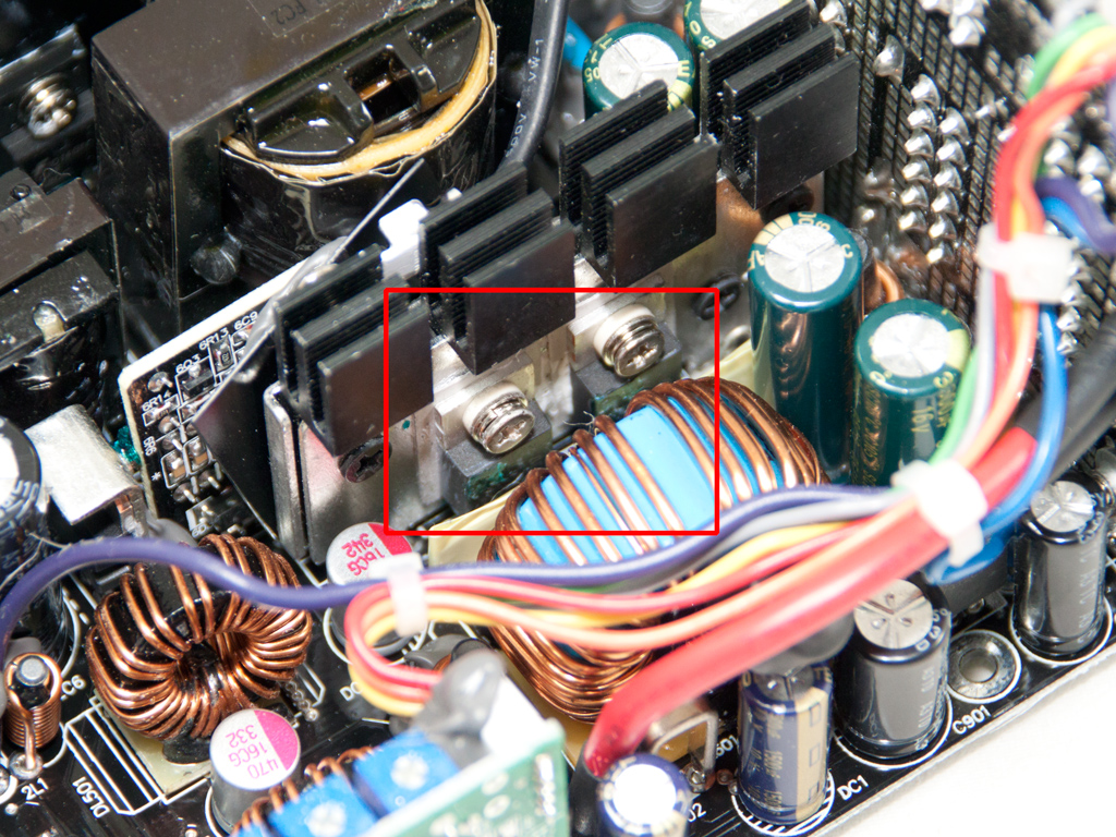
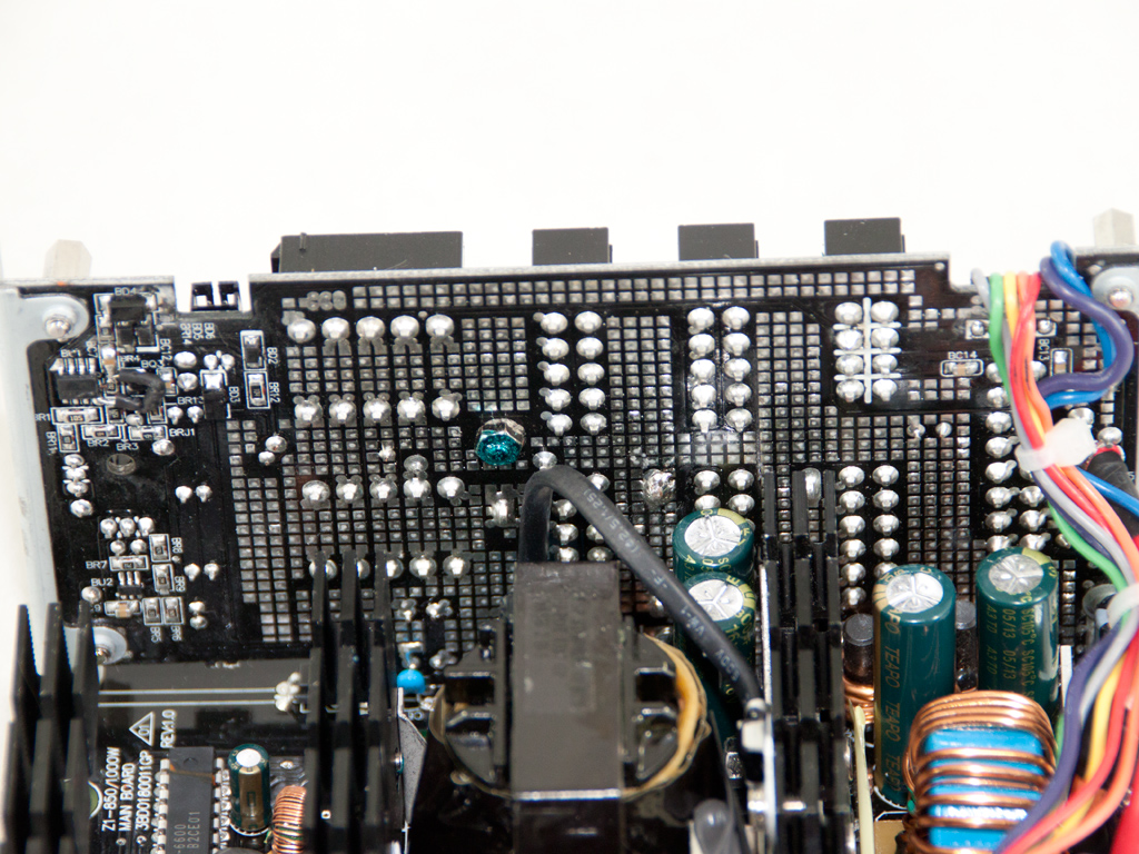
The two parallel bridge rectifiers are bolted to a dedicated heatsink. Their model number is D15XB-60, and each one can handle up to 15 A of current for a combined total of 30 A.

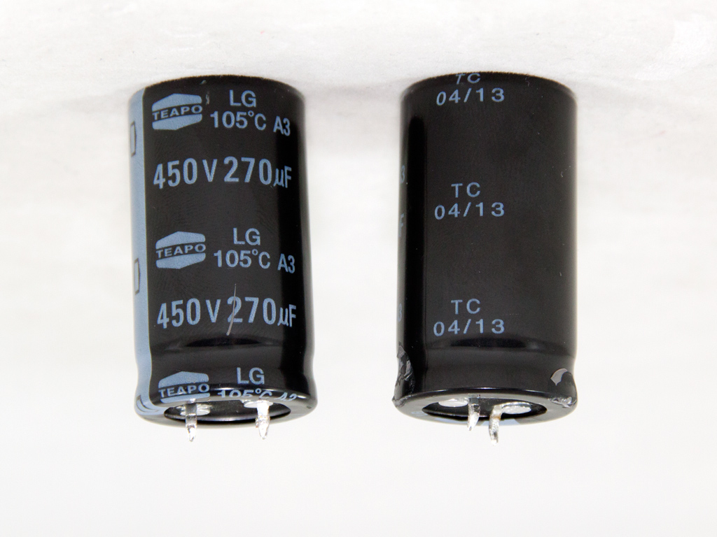
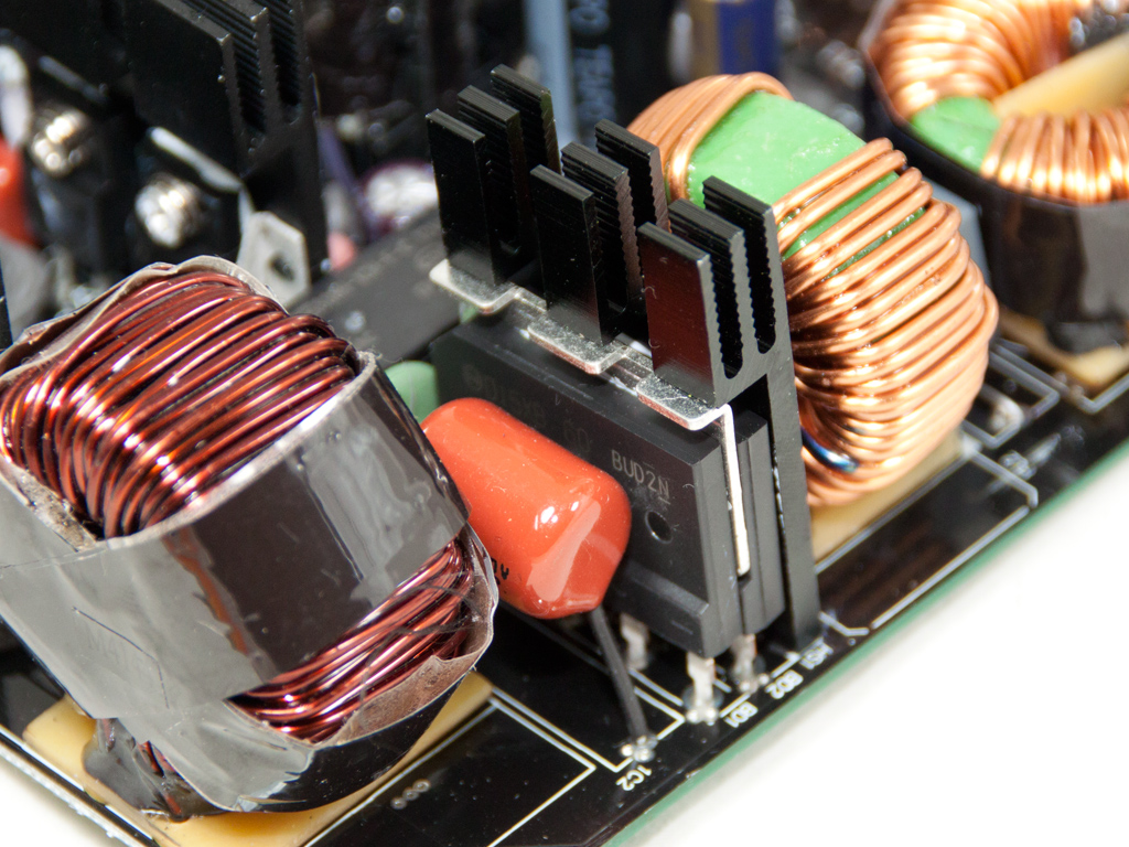
The APFC converter circuit uses three IPA60R160C6 fets and two LXA08FP600 boost diodes. The bulk caps are two Teapos with 540 µF combined capacity (450 V, 270 µF capacity, each, 105°C).
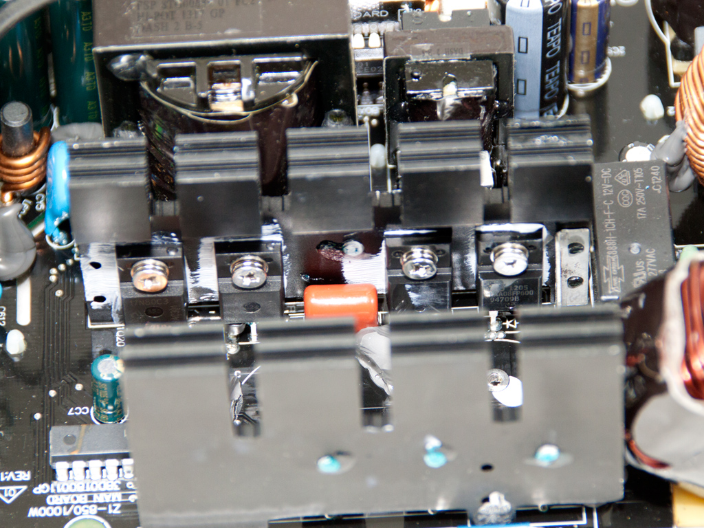
The Active Clamp Reset Forward topology this unit uses makes it highly efficient without the use of exotic components, like LLC resonant converters or fets with ultra-low RDS-on values. Three main switchers are used in this particular case. Two of these act as main switchers (Q1 and Q2) while the third is the reset switch (Q3), which disconnects the bulk capacitors while Q1 and Q2 are active. Also, while Q3 is open, power is transferred from the primary to the secondary side. The main advantage of ACRF is the almost lossless switching of Q1 and Q2, as voltage drained is very low while both are turned off. Two SPA17N80C3s in the Power Zone 1000 W act as respective Q1 and Q2 switches while a FQPF3N80C is the Q3 reset switch. A FSP 6600 IC for which there is no documentation available on the net acts as the APFC/PWM controller.
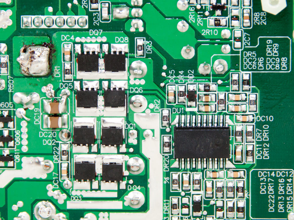
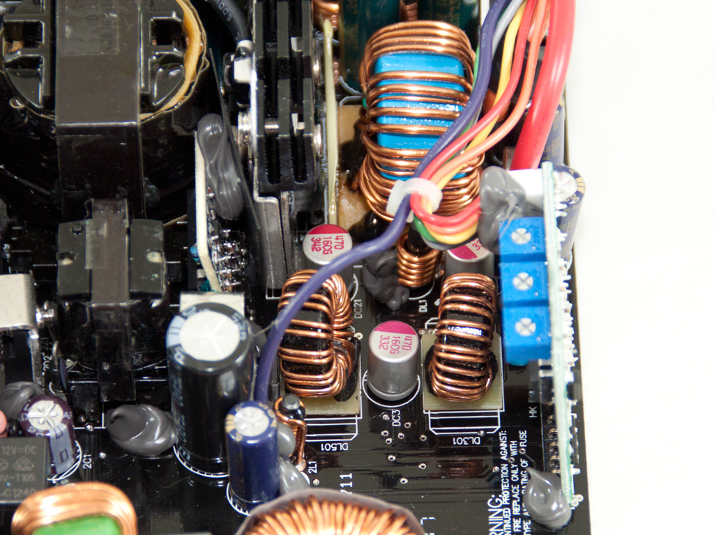
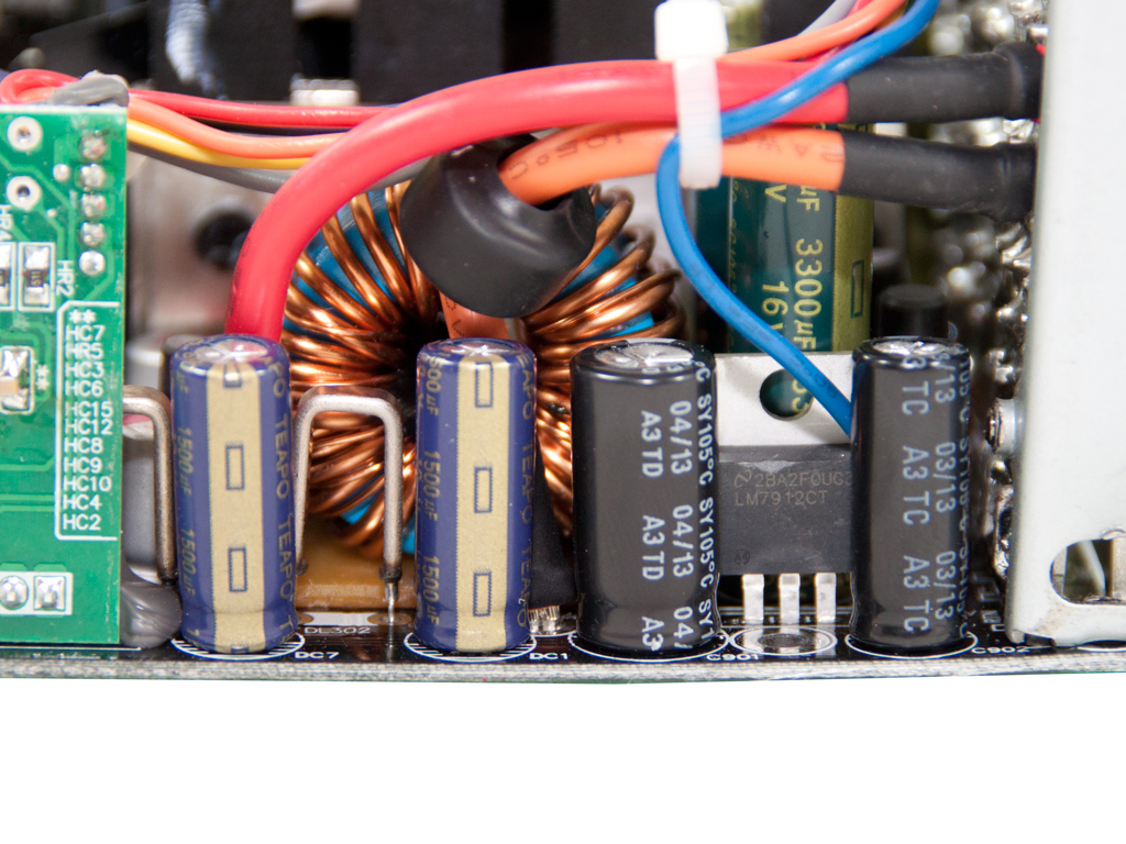
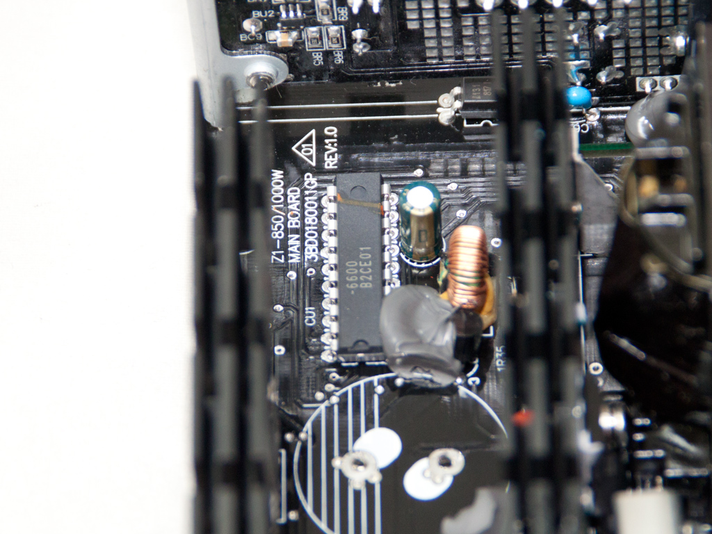
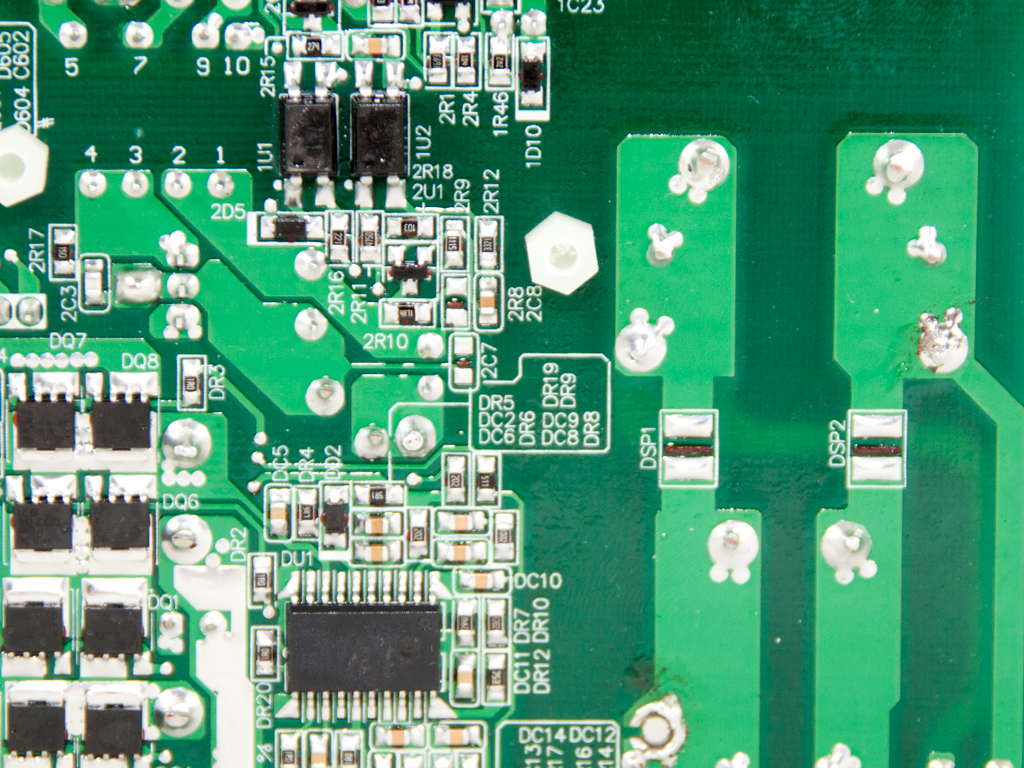
A synchronous design is used in the secondary side, so the generation of +12V is handled by four Infineon IPP023NE7N3 mosfets. The minor rails are generated off +12V with the help of two DC-DC converters. The mosfets responsible for the regulation of the minor rails reside on the solder side of the main PCB and consist of two pairs of PBm1222D4 and PBm1219A5 fets. The common PWM controller for both DC-DC converters is an APW7159 IC, and we also found a proprietary FSP 6601 IC on a vertical daughterboard located on the component side of the main PCB. Finally, all filtering caps of the secondary side, electrolytic and polymer, are provided by Teapo, and all electrolytics are rated at 105°C.

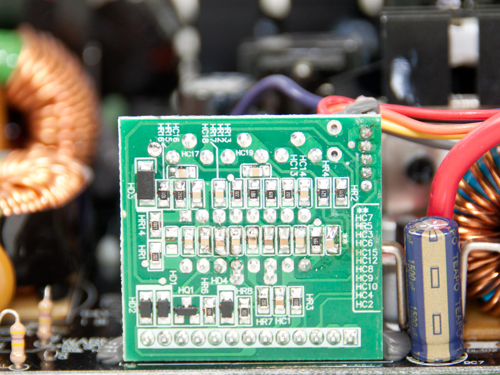
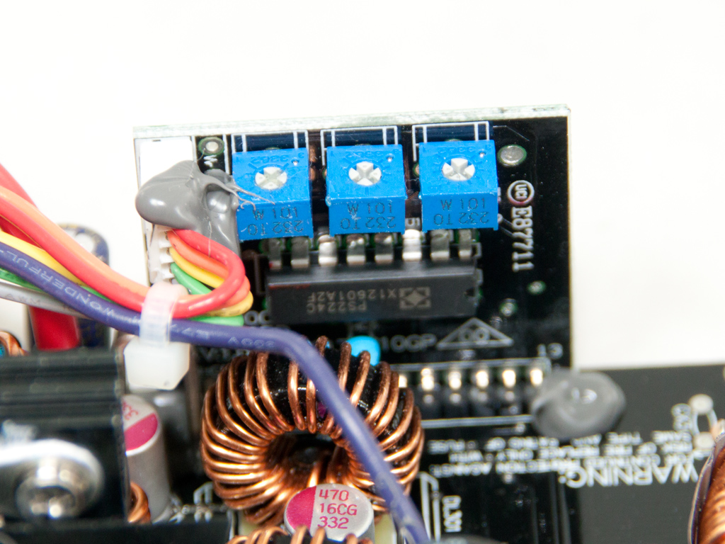
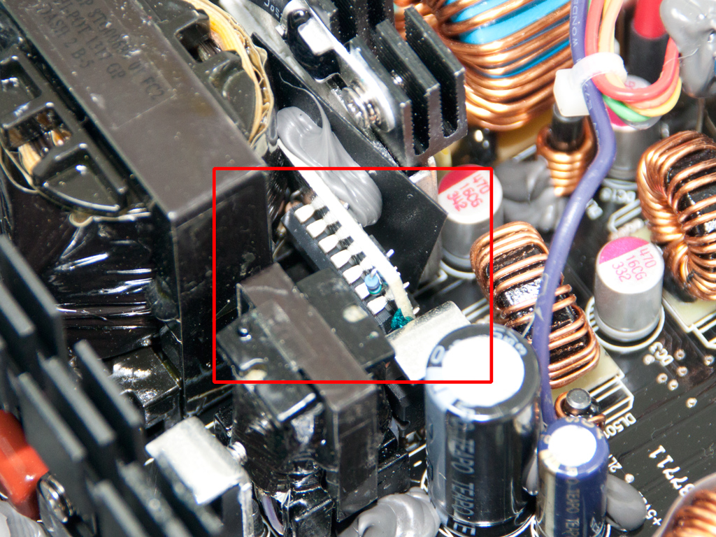
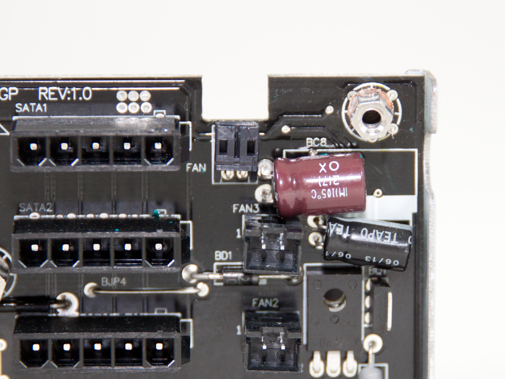
This vertical PCB hosts the supervisor IC, a SITI PS224 that supports all protections except for OTP out of the box. The same IC provides OCP for up to two +12V rails, but this unit only has one. As you can see, there are three potentiometers on top of this daughterboard. These can probably be used to adjust the thresholds of all available protections.
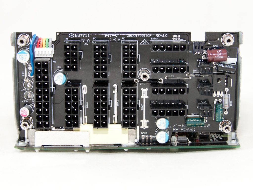

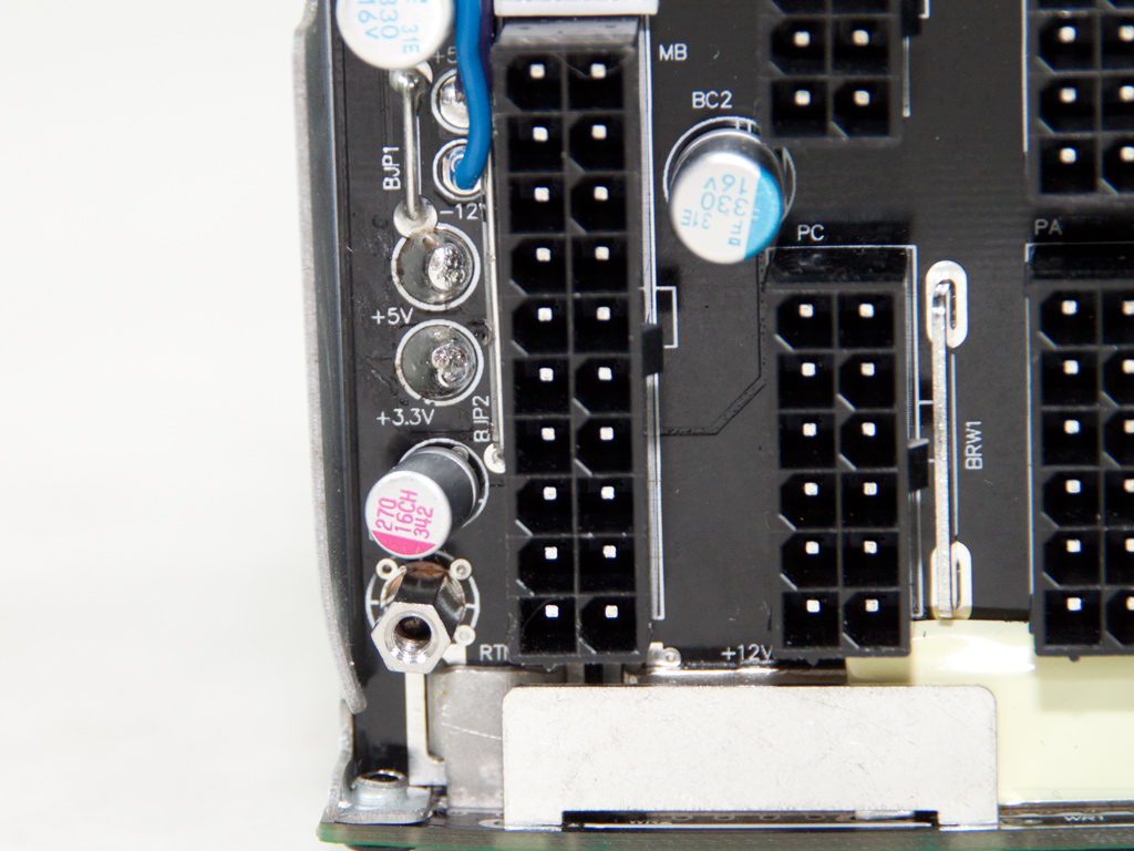
Soldering quality on the modular PCB is good. We find several polymer Nippon Chemi-Con caps, a single Teapo one, and four electrolytic ones on its front. Here, we also find an D882 NPN silicon transistor, which is used by the PSU's fan controller circuit. The aforementioned circuit can control up to three case fans.

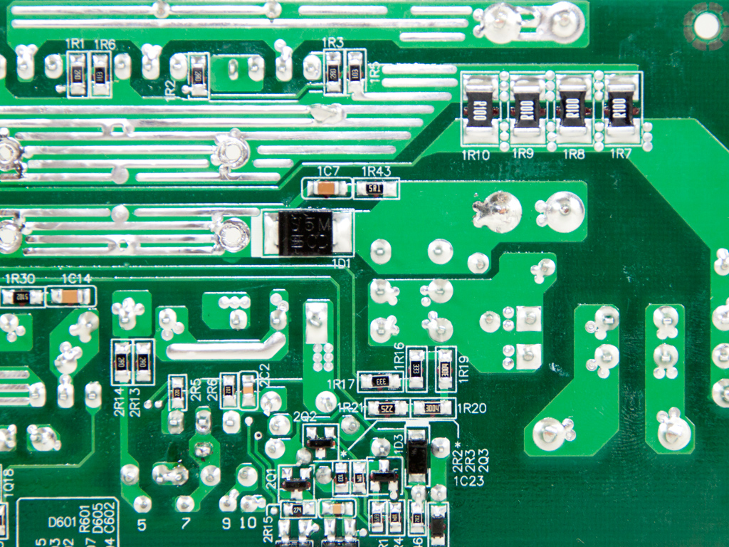

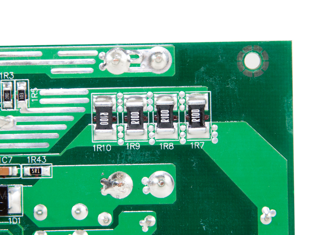
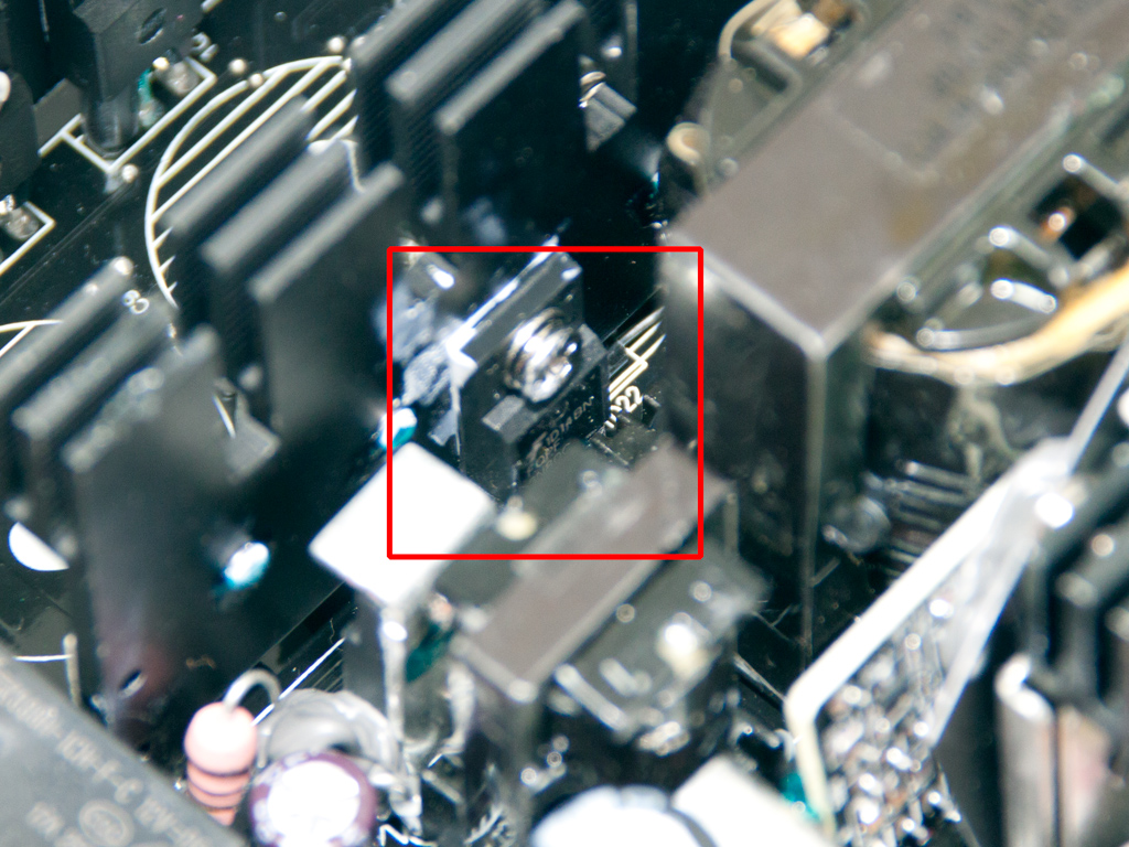
Soldering quality is pretty good, but we spotted several sloppy solder joints. We noticed four current sense resistors, which are usually located under the rail islands, right below the PFC choke. These resistors provide amperage feedback to the OCP circuit.
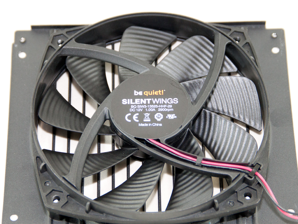
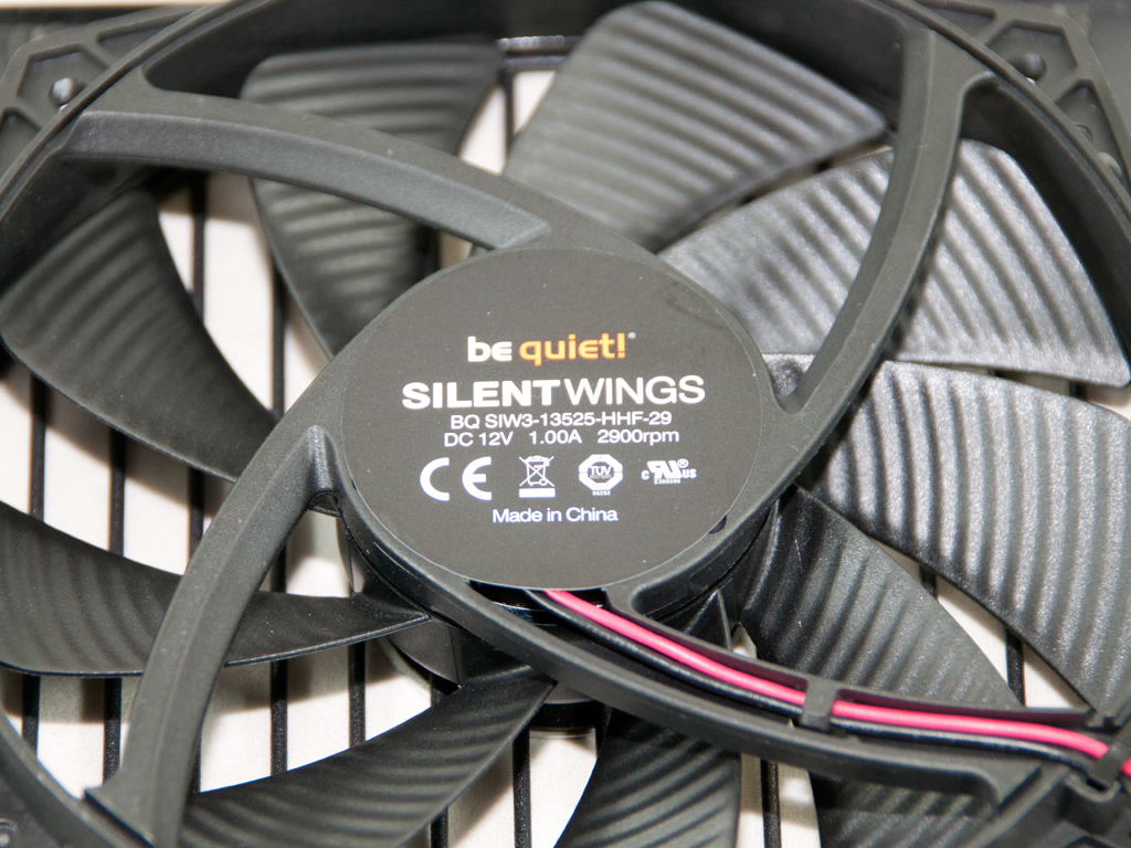
The high quality cooling fan is provided by be quiet! and belongs to the SilentWings series. Its model number is BQ SIW3-13525-HHF-29 (12 V, 1 A, 2900 RPM max), and we strongly believe it to be too powerful and noisy for the needs of this PSU. The fan controller circuit fortunately restricts its maximum rotational speed to 2500 RPM, and it generally rotates the fan at low enough speeds for a quiet, not whisper quiet, operation.
Apr 27th, 2024 14:15 EDT
change timezone
Latest GPU Drivers
New Forum Posts
- Usb 3.2 and usbc speeds became very slow (0)
- What are you playing? (20548)
- Should I install Windows 10 or 11 for my new device (35)
- Ryzen Owners Zen Garden (7250)
- looking to build a new system and im considering asrock brand but i have some doubts/concerns. (20)
- RX 580 VBIOS related functionality not supported for Device: 0x67df (11)
- The TPU UK Clubhouse (24790)
- Your PC ATM (34512)
- Alphacool CORE 1 CPU block - bulging with danger of splitting? (41)
- Liquidextasy waterblocks (54)
Popular Reviews
- Ugreen NASync DXP4800 Plus Review
- HYTE THICC Q60 240 mm AIO Review
- Upcoming Hardware Launches 2023 (Updated Feb 2024)
- MOONDROP x Crinacle DUSK In-Ear Monitors Review - The Last 5%
- Thermalright Phantom Spirit 120 EVO Review
- FiiO K19 Desktop DAC/Headphone Amplifier Review
- AMD Ryzen 7 7800X3D Review - The Best Gaming CPU
- Alienware Pro Wireless Gaming Keyboard Review
- ASUS Radeon RX 7900 GRE TUF OC Review
- Gigabyte GeForce RTX 4070 Ti Super Gaming OC Review
Controversial News Posts
- Windows 11 Now Officially Adware as Microsoft Embeds Ads in the Start Menu (139)
- Sony PlayStation 5 Pro Specifications Confirmed, Console Arrives Before Holidays (117)
- NVIDIA Points Intel Raptor Lake CPU Users to Get Help from Intel Amid System Instability Issues (106)
- AMD "Strix Halo" Zen 5 Mobile Processor Pictured: Chiplet-based, Uses 256-bit LPDDR5X (103)
- US Government Wants Nuclear Plants to Offload AI Data Center Expansion (98)
- AMD's RDNA 4 GPUs Could Stick with 18 Gbps GDDR6 Memory (95)
- Developers of Outpost Infinity Siege Recommend Underclocking i9-13900K and i9-14900K for Stability on Machines with RTX 4090 (85)
- Windows 10 Security Updates to Cost $61 After 2025, $427 by 2028 (84)