 39
39
Corsair AX 860 W Review
Ripple Measurements »Advanced Transient Response Tests
In these tests, we monitor the response of the PSU in two different scenarios. First, a transient load (10 A at +12V, 5 A at 5V, 5 A at 3.3V, and 0.5 A at 5VSB) is applied to the PSU for 200 ms while the latter is working at a 20% load state. In the second scenario, the PSU, while working at 50% load, is hit by the same transient load. In both tests, we measure the voltage drops that the transient load causes using our oscilloscope. The voltages should remain within the regulation limits defined by the ATX specification. We must stress here that the above tests are crucial since they simulate transient loads that a PSU is very likely to handle (e.g., booting a RAID array, an instant 100% load of CPU/VGAs, etc.) We call these tests "Advanced Transient Response Tests", and they are designed to be very tough to master, especially for PSUs with capacities lower than 500 W.| Advanced Transient Response 20% | ||||
|---|---|---|---|---|
| Voltage | Before | After | Change | Pass/Fail |
| 12 V | 12.166V | 12.094V | 0.59% | Pass |
| 5 V | 5.022V | 4.968V | 1.08% | Pass |
| 3.3 V | 3.352V | 3.250V | 3.04% | Pass |
| 5VSB | 5.108V | 5.079V | 0.57% | Pass |
| Advanced Transient Response 50% | ||||
|---|---|---|---|---|
| Voltage | Before | After | Change | Pass/Fail |
| 12 V | 12.137V | 12.070V | 0.55% | Pass |
| 5 V | 5.016V | 4.958V | 1.16% | Pass |
| 3.3 V | 3.348V | 3.235V | 3.38% | Pass |
| 5VSB | 5.074V | 5.040V | 0.67% | Pass |
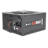
The PSU's response to transient loads is amazing on almost all rails! The deviation at +12V is a little higher than 0.5% on both tests, and it stays around 1% at 5V. The 3.3V rail registers higher deviations than the other rails, but still stays close enough to 3% on both tests.
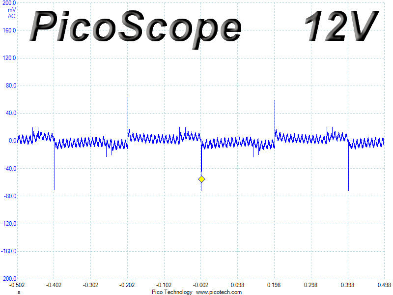
Below, you will find the oscilloscope screenshots that we took during Advanced Transient Response Testing.
Transient Response at 20% Load


Transient Response at 50% Load


Turn-On Transient Tests
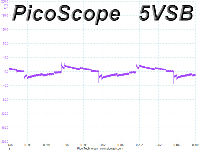
We measure the response of the PSU in simpler scenarios of transient loads - during the power-on phase of the PSU - in the next set of tests. In the first test, we turn the PSU off, dial the maximum current that the 5VSB can output, and then switch on the PSU. In the second test, we dial the maximum load that +12V can handle and we start the PSU while the PSU is in standby mode. In the last test, while the PSU is completely switched off (we cut off power or switch off the PSU's on/off switch), we dial the maximum load that the +12V rail can handle before switching the PSU on from the loader and restoring power. The ATX specification states that recorded spikes on all rails should not exceed 10% of their nominal values (e.g., +10% for 12V is 13.2V and for 5V is 5.5V).
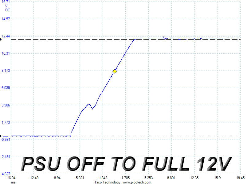
We didn't measure any voltage overshoots during these tests; however, we noticed small spikes (at around 12.4 V) on the last two scope shots. Strangely enough, these spikes occur after the voltage on the +12V rail has been stabilized. This is, nevertheless, nothing to worry about since both spikes are way lower than the allowed limit of 13.2 V.
May 9th, 2024 22:22 EDT
change timezone
Latest GPU Drivers
New Forum Posts
- Could not create driver file(C:\Users\ pzx \AppData\ Local\ Temp\ Throttlestop.sys was not found.)no such file or directory (9)
- AM5 boot times improve RADICALLY with memory context restore enabled (17)
- Graphics card running at 8x 4.0 not 16x 4.0 (2)
- Is hard drive sentinel trustworthy (6)
- dolby pro logic 2x settings menu in windows 10 (0)
- Dell Workstation Owners Club (3071)
- Only some humans can see refresh rates faster than others, I am one of those humans. (238)
- Soundblaster x-ae5 plus sometimes switches center channel to other channels. (2)
- not impressed - nvme vs ssd (76)
- Your way of cooling your PC? (100)
Popular Reviews
- CHERRY XTRFY M64 Pro Review
- Bykski CPU-XPR-C-I CPU Water Block Review - Amazing Value!
- Corsair iCUE Link RX120 RGB 120 mm Fan Review
- Corsair MP700 Pro SE 4 TB Review
- Upcoming Hardware Launches 2023 (Updated Feb 2024)
- Finalmouse UltralightX Review
- ThundeRobot ML903 NearLink Review
- AMD Ryzen 7 7800X3D Review - The Best Gaming CPU
- Sapphire Radeon RX 7700 XT Pure Review
- ASUS Radeon RX 7900 GRE TUF OC Review
Controversial News Posts
- Intel Statement on Stability Issues: "Motherboard Makers to Blame" (264)
- AMD to Redesign Ray Tracing Hardware on RDNA 4 (206)
- Windows 11 Now Officially Adware as Microsoft Embeds Ads in the Start Menu (169)
- NVIDIA to Only Launch the Flagship GeForce RTX 5090 in 2024, Rest of the Series in 2025 (144)
- Sony PlayStation 5 Pro Specifications Confirmed, Console Arrives Before Holidays (119)
- AMD's RDNA 4 GPUs Could Stick with 18 Gbps GDDR6 Memory (114)
- NVIDIA Points Intel Raptor Lake CPU Users to Get Help from Intel Amid System Instability Issues (106)
- AMD Ryzen 9 7900X3D Now at a Mouth-watering $329 (104)