 3
3
Spire BlackDragon 400 W Review
Voltage Regulation & Efficiency »A Look Inside
Before reading this page we strongly suggest to take a look at this article, which will help you understand the internal components of a PSU much better.


The original manufacturer of this unit most likely is Seventeam, the favorite OEM of Spire since most of their units are made by this manufacturer. The main PCB is compact and sparsely populated while all heatsinks are pretty small. Of course with mere 400W capacity there is no need for huge heatsinks and all components can be rather small (e.g. the main transformer and all coils). The design is not modern with an ordinary double forward topology in the primary side while in the secondary a passive design is utilized along with group regulation. So we don't expect to see ground breaking efficiency readings. As usual, to provide a better view we removed some components. In this case the PFC and the secondary heatsinks.
The first part of the transient filtering stage consists of one X and two Y caps. On the main PCB we find the second part which includes one X and two Y caps, two CM chokes and an MOV. All in all the transient filtering stage is complete and we were happy to also see an MOV included.


The bridge rectifier is bolted on the APFC heatsink and its model number is GBU808. Its power rating is adequate for the capacity of the unit. In the APFC we find two FDPF 18N50 fets and the necessary boost diode (STTH15R06D). The smoothing/reservoir capacitor is provided by CapXon and has rather small capacity (220µF). It is rated at 85°C and 420V.

As main switchers two FQPF 12N60C fets are used and a dedicated heatsink is used to cool them down.
As you can see from the photo above the main transformer is tiny, since it has to handle low power levels.


The standby PWM controller is a TNY278PN IC and is soldered on the component side of the main PCB. A little further away we also find the combo PFC/PWM controller, the omnipresent CM6800TX.

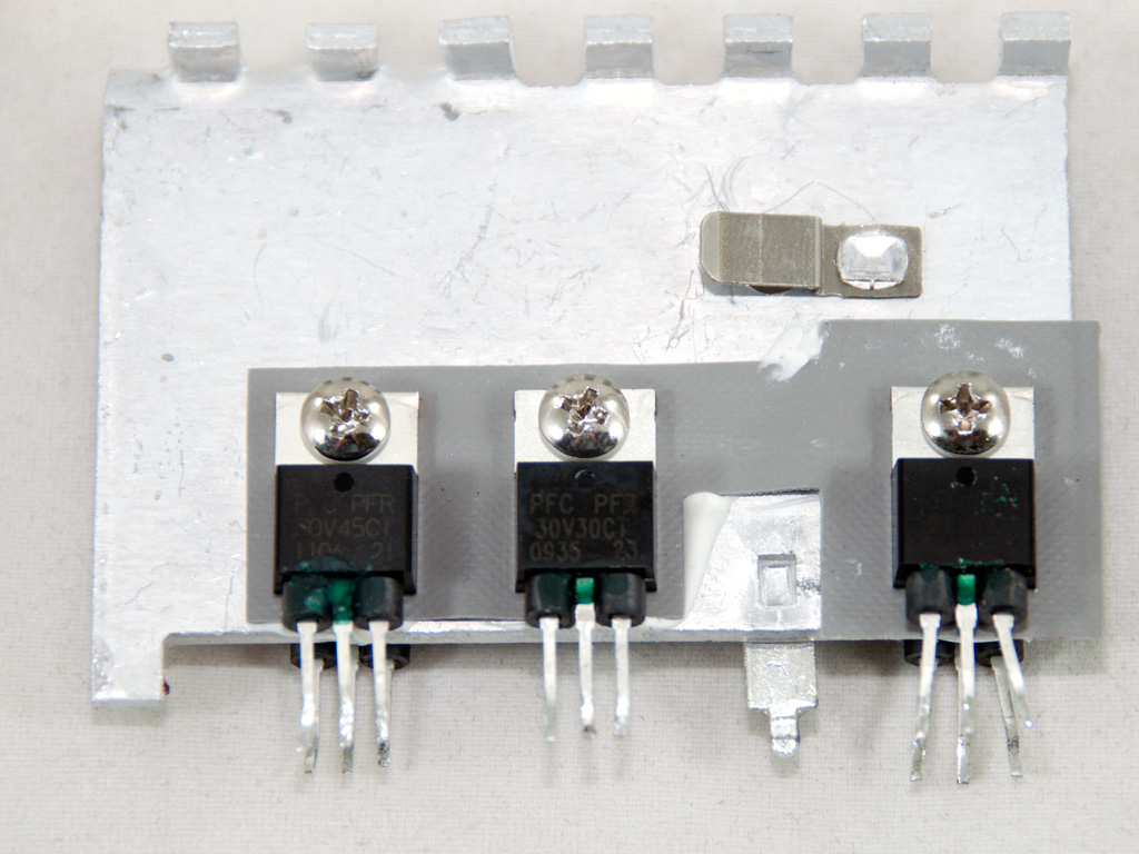
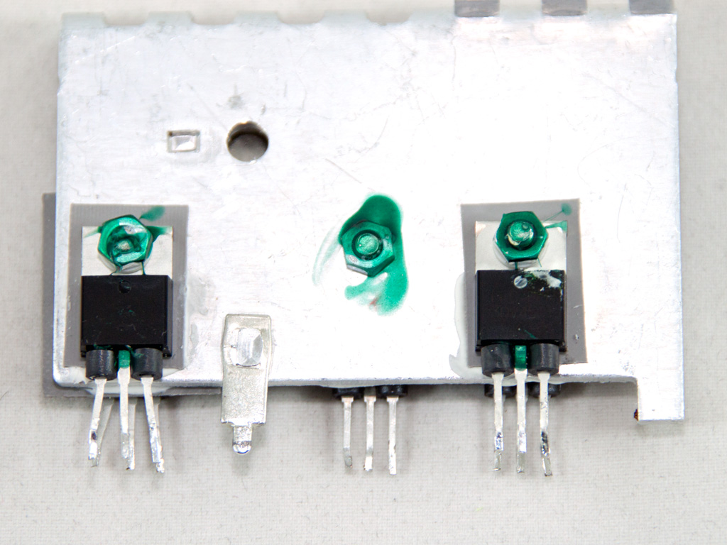


In the secondary side passive design is used so all rails are regulated by Schottky Barrier Diodes (SBRs). Compared to mosfets, these have increased voltage drops, something that leads to decreased efficiency of course. Also a group regulation scheme is utilized and this can be easily figured out by the presence of only two toroidal coils. The larger one is for +12V and 5V while the other one is for 3.3V. In the secondary heatsink we meet two 30L60CT SBRs, responsible for the +12V regulation while the 5V, 3.3V and 5VSB handle two 30V45CT and a 30V30CT SBRs. All aforementioned rails incorporate a PI or capacitor-input filter (consisting of two caps and one inductor) to suppress AC ripple. Also the inductors of the PI filters can be used as current sensors. Finally all filtering capacitors in the secondary are provided by CapXon. We would prefer to see at least Teapo caps used instead.


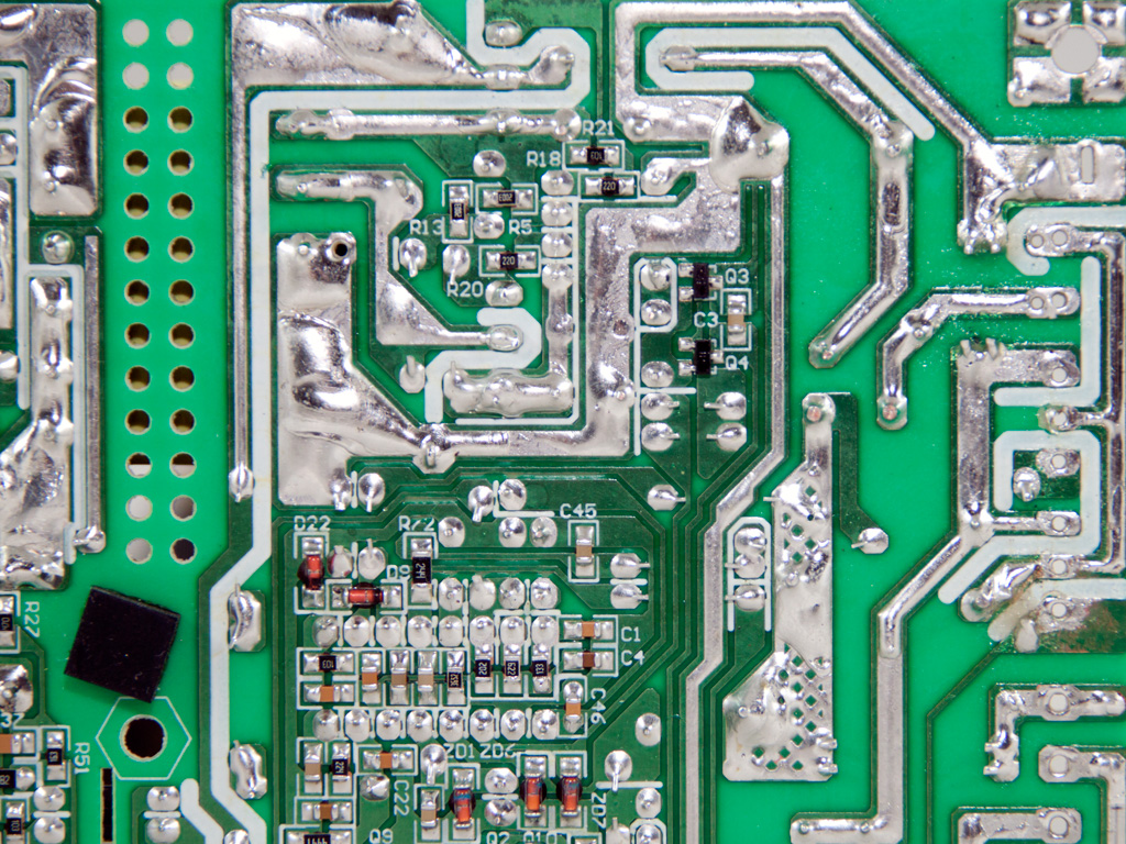


On the solder side of the main PCB things don't look so good. We spotted many hand made, sloppy and blob, solder joints and a huge and ugly grounding trace on the secondary. With only 400W max power we seriously doubt the use of such a large ground trace. Also we discovered that all +12V wires are soldered to the same spot on the main PCB, so in fact this unit uses a single rail design and doesn't have two +12V rails as Spire claims. Also the supervisor IC, which is installed on this side of the main PCB, is a WT7502, an IC that doesn't support OCP protection and on top of that we didn't spot any additional ICs that could implement this protection.

The cooling fan is provided by Spire and is equipped with sleeve bearings. Unfortunately there was no other information, on the center badge, about its model number or any other useful details.
May 1st, 2024 18:06 EDT
change timezone
Latest GPU Drivers
New Forum Posts
- Bykski CPU-XPR-C-I CPU Water Block (1)
- What are you playing? (20564)
- Intel SSD model codes & SanDisk SSD product codes reference list (0)
- Alphacool CORE 1 CPU block - bulging with danger of splitting? (70)
- Arctic MX-6 shelf life is just a couple months? (63)
- 7900 XTX Seriously lacking (97)
- Old high quality PSU, or semi-old mid-quality PSU? (33)
- Ejecting HDDs VS turning them offline (1)
- 2019 LTSC vs 2021 LTSC (1)
- Need help with a persistent infection possible rootkit or other device. (3)
Popular Reviews
- Ugreen NASync DXP4800 Plus Review
- Team Group T-Force Vulcan ECO DDR5-6000 32 GB CL38 Review
- HYTE THICC Q60 240 mm AIO Review
- Upcoming Hardware Launches 2023 (Updated Feb 2024)
- Montech Sky Two GX Review
- MOONDROP x Crinacle DUSK In-Ear Monitors Review - The Last 5%
- AMD Ryzen 7 7800X3D Review - The Best Gaming CPU
- Thermalright Phantom Spirit 120 EVO Review
- ASUS Radeon RX 7900 GRE TUF OC Review
- FiiO K19 Desktop DAC/Headphone Amplifier Review
Controversial News Posts
- Intel Statement on Stability Issues: "Motherboard Makers to Blame" (212)
- Windows 11 Now Officially Adware as Microsoft Embeds Ads in the Start Menu (157)
- Sony PlayStation 5 Pro Specifications Confirmed, Console Arrives Before Holidays (117)
- AMD's RDNA 4 GPUs Could Stick with 18 Gbps GDDR6 Memory (109)
- NVIDIA Points Intel Raptor Lake CPU Users to Get Help from Intel Amid System Instability Issues (106)
- AMD "Strix Halo" Zen 5 Mobile Processor Pictured: Chiplet-based, Uses 256-bit LPDDR5X (103)
- TechPowerUp Hiring: Reviewers Wanted for Motherboards, Laptops, Gaming Handhelds and Prebuilt Desktops (90)
- AMD Ryzen 9 7900X3D Now at a Mouth-watering $329 (88)