• Welcome to TechPowerUp Forums, Guest! Please check out our forum guidelines for info related to our community.

I'm looking for a good tool to make the 3D scanning of my mini-pc using the photogrammetry and my Kinect 2.

Status
Not open for further replies.
Either cable can be used, but I think the trigger cable with the switch is too long.

However, when using the trigger cable, in a dual power bank setup, there is plenty of space to store the extra length of cable.
I like including cable management in case designs.


First let me explain about the short Type-C male to DC barrel plug trigger cable you already purchased.

Connect the Type-C of the trigger cable to the Type-C of the NB10000.

Next, connect the DC barrel plug of the trigger cable to the DC barrel jack of the switched cable you just purchased.

The connection from the switched cable to the RockPro64 is the same, so there's no need to explain it, right?

Oh my God,yes. Everyone has the moment of being an idiot....

Regarding the Type-C trigger cable with a switch, I do not recommend this cable.

Which one ?
 
Which one ?
This one.
1742019424372.png

The shapes are different, right?

I would be too lazy to make a case for both of them, so don't buy the one on the right.
 
This one.

View attachment 389848
The shapes are different, right?

I would be too lazy to make a case for both of them, so don't buy the one on the right.

Sure,I don't like it,the cable its too long.

1741977324600.png


Let's talk a little bit about this idea. I don't dislike it. Can you imagine how to put a little switch in the middle of those wires,that comes out to one side (or on the top) of the case ? As before,with the powerbank...
 
Let's talk a little bit about this idea. I don't dislike it. Can you imagine how to put a little switch in the middle of those wires,that comes out to one side (or on the top) of the case ? As before,with the powerbank...
Of course, this idea and the idea of adding a switch can both be implemented at the same time.
I would like to incorporate this idea.

I would also like to install a DC barrel jack for charging the 3S2P battery on the outside of the case.

The necessary parts have already been presented. It can be fixed neatly into the case.

EDIT:
DC Panel Jack found a potential hazard in the product review and replaced it with a link to a different, equivalent product.
 
Last edited:
Of course, this idea and the idea of adding a switch can both be implemented at the same time.
I would like to incorporate this idea.

I would also like to install a DC barrel jack for charging the 3S2P battery on the outside of the case.


The necessary parts have already been presented. It can be fixed neatly into the case.

I don't understand how to implement it.
 
I don't understand how to implement it.
DC barrel jacks require a lot of force when inserted and removed, so you want to make sure they are firmly attached.

So I would like to use a DC barrel jack that can be screwed on.
1742039497842.png


Dust caps are included, but you can choose to use them or not.
I wouldn't use them if I was using it indoors.
I don't like protrusions that stick out from the case...

EDIT:
DC Panel Jack found a potential hazard in the product review and replaced it with a link to a different, better equivalent product.
The right choice https://www.amazon.it/dp/B0CH7WX85X/
Products found to be dangerous https://www.amazon.it/dp/B0C6MBYRYG/

The reviews deemed dangerous can be found on this equivalent product's page.
1742045567269.png

1742045000137.png


Now, there's one more thing I want to check.
Using two 90 degree USB adapters (the first one will be attached to the USB 2.0 port and the other one to the USB 3.0 port) like the one below will allow to make a very little hole on the back :

https://www.amazon.it/Gbformat-Adattatore-Maschio-Femmina-Adattatores/dp/B0CR61Q9B9/
because they will come out of the back,just ready to attach to them what you want without sticking the hands inside the case....
Have you actually purchased the USB A 90 degree conversion adapter that you are proposing?

There is no dimensional information, so I expect that the accuracy of the CAD study will be low.

I found a nearly identical product and will use the dimensions as a reference. Is that okay?
...That said, even this product image is missing some important dimensions, so I'm not sure if it's helpful.
1742042069121.png


Hold on!

Did you really buy the product from this link?
Incorrect product : https://www.amazon.it/dp/B0D56PS8XV

This is a 15V PD trigger.

If so, it won't work with the NB10000.

The correct product option is 12V trigger cable.

Just to be safe, I'll explain what happens if you use a 15V trigger.

Case 1: When a 15V trigger is inserted into the NB10000's Type-C connector.
As a result, no power is output from the DC barrel plug.

It won't break anything, but it won't work properly either.


Case 2: When a 15V trigger is inserted into a PD45W or higher wall charger.
As a result, 15V is output from the DC barrel plug.
When connected to the RockPro64, it will probably work normally, but it won't be in very good condition.

After analyzing the circuit diagram in the past, I found that the power circuit itself will function up to 18V.
However, since the internal eDP power supply uses 16V-resistant MLCCs, it must never exceed 16V.


A rated 12V voltage is 75% (3/4) of a 16V voltage resistance.
15V is 93.8% of a 16V voltage resistance.

Based on my design experience, I am careful to only apply a voltage of 2/3 of the MLCC's voltage resistance.

In the past, I have had a case where a client changed the power supply specifications without notifying me, the designer, and applied a voltage of 80% of the MLCC's voltage resistance, causing the MLCC to catch fire.

When actually testing this design example, we found that the component configuration caused a short-term voltage rise.

Measurements showed that a voltage of 250% of the MLCC's voltage resistance had been applied.
 
Last edited:
This scheme is different from this one :
Yes.
Because this suggestion is a way to charge the "Liitokala 3S2P Battery Pack".
I would also like to install a DC barrel jack for charging the 3S2P battery on the outside of the case.

You insert the included dedicated AC-DC charger into the DC barrel jack of the 3S2P battery pack, right?
What I've shown in this post is a way to attach this charging barrel jack to the case and charge it easily.
There's no need to open the case of your tablet PC and disassemble it to charge it.

EDIT
The following three ideas can all be done at the same time.
- How to fix a jack that can be exposed to the case for 3S2P battery charging.
- How to use a smart JST HX 4Pin connector instead of the RockPro64's DC barrel jack.
- How to add a switch to stop power supply to the RockPro64.


Okay.
Would you use an adapter like this to access it from the back?

Another idea I'm considering is a dual-layer back cover.
A sliding or magnetic cover would be placed on the back cover, allowing direct access to the USB on the RockPro64 when the cover is opened.
A hole would be provided for the connected cable to come out, making it look smart.
Since only the cable would come out of the tablet, there would be no risk of hitting the USB connector with something and damaging the RockPro or the case.


Nope. I took it only as an example...
That would be fine.
 
Last edited:
What I've shown in this post is a way to attach this charging barrel jack to the case and charge it easily.

I don't see the utility. It works good as is. The cable used to recharge the battery pack comes out of the case and I will attach the charger to it.
I find more useful to add a switch between the wires which prevents the power to go from the battery pack to the rockpro. This is because if I use the battery pack and I want to power off the device,I don't have a way to do it because the battery pack does not have the switch and if I want to turn off the Rockpro I should press the button that's in the back. It can be done almost easily,but the switch will make the shutdown operation more comfortable.

Would you use an adapter like this to access it from the back ?

yeah.

Another idea I'm considering is a dual-layer back cover.
A sliding or magnetic cover would be placed on the back cover, allowing direct access to the USB on the RockPro64 when the cover is opened.
A hole would be provided for the connected cable to come out, making it look smart.
Since only the cable would come out of the tablet, there would be no risk of hitting the USB connector with something and damaging the RockPro or the case.

Sounds good and I would like to understand better how it works. You can help me provinding a video that shows and explain the behavior that you have explained in words. Be careful not to overcomplicate things, otherwise when I get the case printed, I'll spend a lot of money.
 
Sounds good and I would like to understand better how it works. You can help me provinding a video that shows and explain the behavior that you have explained. Be careful not to overcomplicate things, otherwise when I get the case printed, I'll spend a lot of money.
For example, this is close to what you'd imagine.
This is an official tutorial video for Internet equipment that uses optical fiber in Japan.

Since optical fiber is sensitive to bending, a connector and ample space are provided inside the double-layered cover.

I've been using 3D printers myself since the early days of 3D printing.
I have over 10 years of experience.
I'm using various know-how to design cases to shorten printing time, optimize the structure, and save materials.
However, this case is large, so I don't know what will happen if I ask a company to do it.

Professional 3D printers and personal 3D printers like the ones I have have fundamentally different mechanisms.

The SLS 3D printers used by professionals are extremely accurate and strong, and produce a beautiful finish.
Above all, they take a short time to manufacture, making them suitable for mass production.
* Conversely, if you don't mass-produce, the maintenance costs of the equipment aren't worth it.

FDM 3D printers like the ones I use (There are also expensive FDM printers for professionals and I have used them) take a long time to print and are less strong.
Above all, there are many restrictions on the shapes that can be printed.
You need to understand these things well before designing.

The advantages of the FDM method are its ease of management, low maintenance costs, and low material costs.
The "material cost" when prototyping this case on the 3D printer I provided would probably be less than 8€.

It all comes down mainly to the time and effort required for design.
If I were to take on this case as a personal commission, the cost would be negotiable, but I would think it would be around 300-500€ at the very least.


I can get a free estimate from a general 3D printing company in my country, so I can contact you about the cost.
*As I said before, I don't intend to use CAD on weekends, so I'll estimate the printed parts after Monday.

Of course, I have my own 3D printer, so I have never used this company.

I have used another company for work, and they had very good technical support.
However, it cost about twice as much as DMM.make.
For the business, this was a necessary price to pay, and very worthwhile.


I don't see the utility. It works good as is. The cable used to recharge the battery pack comes out of the case and I will attach the charger to it.
Did I mention I had a lithium battery fire?

Leaving that all-important charging "cable" outside the case is a dangerous idea.
When pulled, it puts force directly on the battery inside the case.
If you secure the cable to prevent this, it will put stress on the cable and risk breaking or shorting it.
 
Last edited:
Did I mention I had a lithium battery fire?

Leaving that all-important charging "cable" outside the case is a dangerous idea.
When pulled, it puts force directly on the battery inside the case.
If you secure the cable to prevent this, it will put stress on the cable and risk breaking or shorting it.

ok. I have understood the point. What about creating a sliding door to extract the battery pack and charge it while keeping it outside the case? After all, that's how it works for the smarphones. While they're charging, you can't use them. Or while one battery pack is charging you could use another batterypack. On AliBaba it costs only 20 Euros.
 
Designing a case that is both easy to disassemble and replace parts, and has a method of safely and securely fixing the parts is very complicated and time-consuming.

I could design it like that, but would you allow it if I charged you 100€ for the design fee?

I think the less opportunity there is to tamper with the battery wiring inside the case, the safer it will be.
Therefore, I would propose a method of fixing the charging connector to the case.
If you provide a DC barrel jack inside the double-layered cover on the back, as I suggested earlier, it should be very safe and look good.
 
Designing a case that is both easy to disassemble and replace parts, and has a method of safely and securely fixing the parts is very complicated and time-consuming.

I've been working on my layout for several months (without using CAD ok, but moving the various components in different ways every day under my eyes) and I can tell you that my layout contemplates many scenarios, even that of keeping the batteries and the board fixed through perforated compartments and that of being able to extract the batteries simply using a door on the top and at thew bottom of the device hooked like the cover. Did u understand how ? Do you want to try to implement it ? Maybe you can't because you won't use the plastic and the hooks used by the PlayBOX enclosure.
 
Last edited:
Regarding this enclosure :

https://it.rs-online.com/web/p/contenitori-per-applicazioni-generiche/1748960

Can you tell me what the height of the product is ? (not the depth) ; because looking at the picture,it can't be 24 cm. If it was 24 x 24 cm,it would be a perfect square shape. But it looks like a rectangular shape.

Thank you very much.
Did you look at the datasheet in that link? it says they do multiple sizes (30) From 100 x 67 x 22.5mm to 240 x 240 x 60mm.
 
Regarding this enclosure :

https://it.rs-online.com/web/p/contenitori-per-applicazioni-generiche/1748960

Can you tell me what the height of the product is ? (not the depth) ; because looking at the picture,it can't be 24 cm. If it was 24 x 24 cm,it would be a perfect square shape. But it looks like a rectangular shape.

Thank you very much.

The model number is PF24-4-24D.

This represents 240 * 40 * 240 mm.
And the color is dark gray.

This is common on e-commerce sites, but when there are many variations of a product, photos may only show a representative example.
It is not uncommon to see photos that show a completely different appearance from the actual model number.
Amazon is the same.
You should be careful when purchasing.
1742267909724.png


All explanations are in the previous post.

First of all, I haven't found any options for PF24-4-17W available in your country. (It was one of the options I had looked into in detail in the past, but I've now abandoned it.)
I thought I explained that in the past.
It may be possible to purchase it from Amazon Japan by adding shipping costs.
For reference, here is the sales page for TAKACHI cases that may be available in your country.

RS ONLINE

When I checked, I found that they had PF24-4-24D and PF24-4-24W (different colors), but not sizes PF24-4-17 or PF24-6-17.

*I will explain again to avoid any misunderstandings.
- I have abandoned consideration of the TAKACHI parts of case.​
- The PF24-4-24W and PF24-4-24D are square, not rectangular.
In my opinion, this case will definitely fit all the components.​
You can also choose a larger power bank or a 3S4P to 3S6P battery.​
A guide to the information you should look at to find cases on the TAKACHI website.

As a side note, the display would not fit into a case that was one size smaller than the PF24-4-24W.
Please see the model number list for NETWORK PLASTIC BOX - PF series.
The model number 24-4-24 represents the external dimensions of the case: 240mm x 40mm x 240mm.The usable internal dimensions are 187.6mm x 29.5mm x 229.5mm.It's better to read these dimensions as 229.5mm x 29.5mm x 187.6mm, since you'll probably want to use it in landscape mode.The display dimensions were 195.5mm x 11.4 x 120.8mm, so you can see that it will fit in the case.You'll notice that unlike the cases you've been building so far, there's space around the perimeter to place components without having to stack them on top of the display.
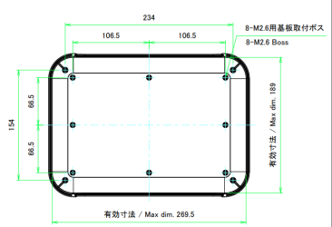
And the thing you really need to check is the Recommended PCB dimension on page 3 of the PDF drawings for each case.
*Do not make the mistake of looking at page 4. The dimensions on page 4 are for the lid (bottom of the case), which is slightly larger than the ones on page 3. If you stack them all together to an inner height of 29.5 mm using the dimensions on page 4, they will not fit into the case.
1741666947669.png

1741667000437.png
1741667020906.png

If you look at the Recommended PCB dimensions you will see that it is a cross shape.This is the true maximum size of the components that can fit into the case.The effective internal dimensions just show the largest rectangle within the Recommended PCB dimensions.
1741667859602.png
Place the component within the recommended PCB dimensions.
The effective internal height of the case is 29.5mm, but this is reduced by the height of the screw mounting studs inside the case that you will probably not use.
If you cut off the 5mm high studs on both sides with pliers or something, the height inside the case will be 39.5mm.

This is a rough example of placement by me and is by no means accurate.
If you look at the outside of the case, it looks like this:
1741669022043.png
1741669551012.png

The case I am currently designing is from scratch.
I have not used either the PINE64 or the PF24-4-17 as reference at all.
You are free to purchase PF24-4-24, PF24-4-17, etc., but this will not have any influence on my case design.
In particular, there is a possibility that the display will not fit into the PF24-4-17.
(I expect it will fit if the dimensions of the rounded corners of the display are R3.0 or more.)
 
Last edited:
The effective internal height of the case is 29.5mm, but this is reduced by the height of the screw mounting studs inside the case that you will probably not use.

Nice point. If I would take the TAKACHI case only as a mockup model,I will not use the screws,so I think that I should take in consideration its external dimensions.

Otherwise,If I would take the TAKACHI case as the effective case,I will use the screws,so I think that I should take in consideration its internal dimensions.

But that's only the plan B. I would like to consider the layout of the case that you are creating as plan A. Can you explain what you want to do ? It seems that you want to rethink the case from scratch.


1741669022043.png


Are these calculations made with the RockPro placed vertically ? I want to place it horizontally,so I suspect that they are not valid.

What about the model PF28-5-20D ?

external dimensions = 280 45 200
internal = 223.6 31.4 189.3
 
Last edited:
This layout was created before I understood your RockPro64 layout and its intentions.

No further explanation is needed... right?
You don't need to worry about my layout, and in the first place, this layout has no dimensional accuracy, so it's unclear whether it can be put into practice.


Now, the dimensions of the case you chose, PF28-5-20D, have enough capacity and I think it's a good balance that's not too big.

If you can buy it, you can try it out.


1742374443421.png


This is a diagram of the inside of the PF28-5-20D.
The location of the mounting screws is indicated.

The dimensions of the display you want to use are as follows.
Overall Dimension 196.00(H) × 121.00(V) × 11.6(D)

You can calculate whether the display will fit using the "8-M2.6 boss" on the diagram.

106.5 + 106.5 - 5.0 = 208.0(H)
208.0(H) > 196.0(H) ...OK!

66.5 + 66.5 - 5.0 = 128.0(V)
128.0(V) > 121.0(V) ...OK!

The calculation shows that the display can be placed in the center without losing any of the "8-M2.6 bosses".


Considering the placement of the display's connectors, it looks like it's necessary to place it closer to the bottom.
Otherwise, one of the "8-M2.6 Boss" will interfere with the position of the display's "POWER" Type-C connector.
1742375697449.png
 

Attachments

  • 1742374246162.png
    1742374246162.png
    50.1 KB · Views: 40
Last edited:
This layout was created before I understood your RockPro64 layout and its intentions.

No further explanation is needed... right?
You don't need to worry about my layout, and in the first place, this layout has no dimensional accuracy, so it's unclear whether it can be put into practice.


Now, the dimensions of the case you chose, PF28-5-20D, have enough capacity and I think it's a good balance that's not too big.

If you can buy it, you can try it out.


View attachment 390520

This is a diagram of the inside of the PF28-5-20D.
The location of the mounting screws is indicated.

The dimensions of the display you want to use are as follows.
Overall Dimension 196.00(H) × 121.00(V) × 11.6(D)

You can calculate whether the display will fit using the "8-M2.6 boss" on the diagram.

106.5 + 106.5 - 5.0 = 208.0(H)
208.0(H) > 196.0(H) ...OK!

66.5 + 66.5 - 5.0 = 128.0(V)
128.0(V) > 121.0(V) ...OK!

The calculation shows that the display can be placed in the center without losing any of the "8-M2.6 bosses".


Considering the placement of the display's connectors, it looks like it's necessary to place it closer to the bottom.
Otherwise, one of the "8-M2.6 Boss" will interfere with the position of the display's "POWER" Type-C connector.
View attachment 390523

It seems nice. And only a minor change is needed to make it work perfectly,right ? It's right that I found a nice case only using my intuit,without making all the measurements :)

Einstein said: "Imagination is more important than knowledge. Knowledge is limited. Imagination encompasses the world.

:D ; for sure both are needed.
 
Last edited:
Most of the design elements have been implemented.

I have also implemented one sliding cover.

I also plan to add sliding covers for charging the power bank and connecting a LAN cable,
as well as adding an exhaust vent and a 3S2P battery fixing mechanism.
1742689190503.png
1742689173532.png
1742689530753.png


1742689651855.png


1742689671263.png


1742689688196.png
 
It is becoming so sexy,our love :love:.

It is becoming so sexy,our love :love:.

Why are you laughing @Canned Noodles : have you ever felt the strong emotion of creating something ? It's a great feeling what you feel...It happens when you believe in something and invest time and energy and see that a miracle come true...
 
Last edited:
It is becoming so sexy,our love :love:.


Why are you laughing @Canned Noodles : have you ever felt the strong emotion of creating something ? It's a great feeling what you feel...It happens when you believe in something and invest time and energy and see that a miracle come true...

Can you elaborate more ?
 
It is becoming so sexy,our love :love:.


Why are you laughing @Canned Noodles : have you ever felt the strong emotion of creating something ? It's a great feeling what you feel...It happens when you believe in something and invest time and energy and see that a miracle come true...
If you cannot see the humor in a grown man talking to another grown man about a diy tablet and calling it sexy, then calling it a miracle of creation, then I don't think we can explain it to you here.

+2 more respect points for S-TKUC
 
If you cannot see the humor in a grown man talking to another grown man about a diy tablet and calling it sexy, then calling it a miracle of creation, then I don't think we can explain it to you here.

+2 more respect points for S-TKUC

Surely you and me don't play the same music. What I can't stand about you is a sort of intolerance that I perceive you might have with those who don't play the same music that you play or a music that you don't like. Instead of saying, okay we don't vibrate in the same way, it's okay, you continue to say and not say, increasing the score for S-TKUC (and that's okay, he's great), but for me there is never an appreciation for the time and resources that I put into the project. Your continuous desire to indirectly devalue my efforts, I find it an ambiguous behavior and a little bit intolerant towards cultural and sensitivity diversity,by the way, that you deduce based on what you read, because you can't see / feel my emotions in real time. But you attribute to me what you perceive without even asking yourself the question if evaluating whether what you perceive can be compatible with what I perceive. My two cents as a psychologist.
 
Last edited:
Surely you and me don't play the same music. What I can't stand about you is a sort of intolerance that I perceive you might have with those who don't play the same music that you play or a music that you don't like. Instead of saying, okay we don't vibrate in the same way, it's okay, you continue to say and not say, increasing the score for S-TKUC (and that's okay, he's great), but for me there is never an appreciation for the time and resources that I put into the project. Your continuous desire to indirectly devalue my efforts, I find it an ambiguous behavior and a little bit intolerant towards cultural and sensitivity diversity,by the way, that you deduce based on what you read, because you can't see / feel my emotions in real time. But you attribute to me what you perceive without even asking yourself the question if evaluating whether what you perceive can be compatible with what I perceive. My two cents as a psychologist.
2 cents plus 3 dollars will buy you a cup of coffee. I think that you wanting to build your own tablets and cell phones without even the willingness to learn how to solder, use cad, or code is funny, and perhaps a bit naive.
 
Status
Not open for further replies.
Back
Top