• Welcome to TechPowerUp Forums, Guest! Please check out our forum guidelines for info related to our community.
  • The forums have been upgraded with support for dark mode. By default it will follow the setting on your system/browser. You may override it by scrolling to the end of the page and clicking the gears icon.

Problem flashing Bios - Msi R9 280

View attachment 77672

You will need to read me what that chip says, it will be faint. Try angling it in the light so the letters show up better. A camera wont catch it unless you have a micro lens. Also did this issue happen After you removed the cooler?
i managed to read the first line that says pm25ld020 and the second that says ce1315, maybe i'm wrong with the second i'm trying to read the third

maybe the third line can be h04fsxb
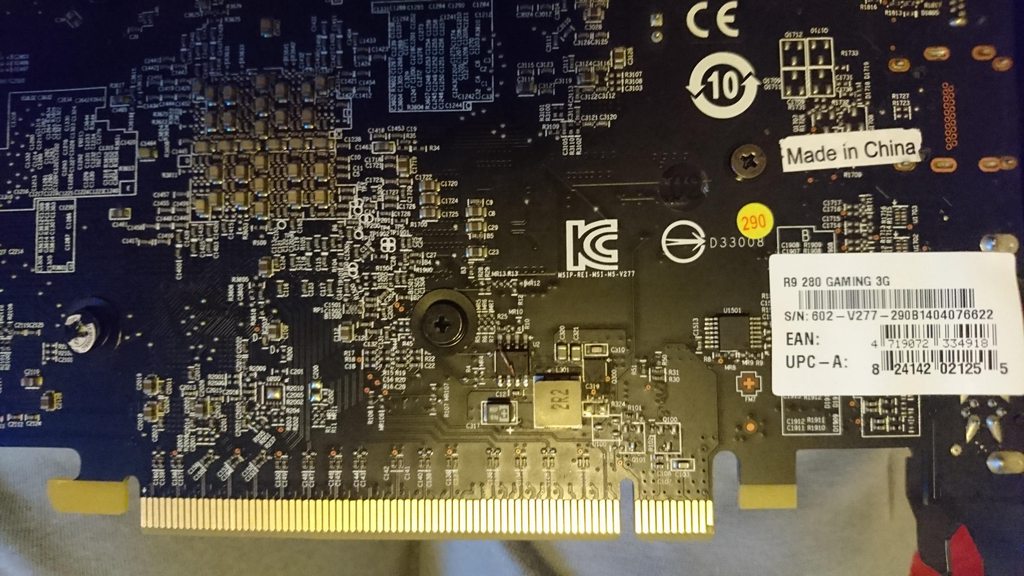
 
Winbond chip?
 
That is the flash memory. This is teh relevant data sheet.

http://www.datasheetspdf.com/PDF/Pm25LD020/818450/3

The dimple on the chip designates PIN #1 and should provide as orientation.

You might be able to manually force a low reading on the chip (enabling write access) by using one of the following methods.

A: Short (connect together with thin wire) PINS #6 and #5.

pins1.png


B: Short PINS #4 and #7

pins2.png
 
That is the flash memory. This is teh relevant data sheet.

http://www.datasheetspdf.com/PDF/Pm25LD020/818450/3

The dimple on the chip designates PIN #1 and should provide as orientation.

You might be able to manually force a low reading on the chip (enabling write access) by using one of the following methods.

A: Short (connect together with thin wire) PINS #6 and #5.

View attachment 77673

B: Short PINS #4 and #7

View attachment 77674

ooook, i never done something like this, so i have to ask you some things :
1) in the A method i have to connect 6 and 5 (sck with sio) or 6 and 7 (sck with hold#) as you wrote?
2) how i connect them? from the back side or removing the cooler and doing everything in the front side? what should i use to connect them? have i to weld they with something?
thank you soo mutch for the help

As I explained you use a thin wire, tweezers, or anything else you have handy that wont touch the pins around it.

You can try and use method A or B This will probably take you several tries. Just dont do both at once.

You will need to have them connected when you boot the system (so you can flash it) but you must not boot the system into windows with the wire connected. It is only for enabling write access.
ok, i'll try
 
Withe te wire connected you boot into ATIflash and see if you can write too it.
 
using regular commands?

yup, The wire modification only attempts to FORCE the chip into write mode. Nothing changes on how to flash it.

You will probably not succeed the first time.
 
i connected they in this way, but it don't work, can yiu please sign on the photo where pins 5 and 6 are?
thanks
 

Attachments

  • photo_2016-08-07_19-19-49.jpg
    photo_2016-08-07_19-19-49.jpg
    130.3 KB · Views: 951
I watched what you told abouth the first pin, so i connected 4 with 7, first time it has done a spark and the wire burned, this time, it haven't done any spark but i have the same error.
Where am i wrong?
HvhPgQuh.jpg
 
now you have gone and killed the chip
its officially done now
sorry about your luck
 
I legitimately drew the lines on the datasheet. I cannot help you with this, I am not physically there. If you still cant manage it you will need to bring it to someone that has a flash tool and hope the chip just isnt damaged to begin with; which could have been the issue from the very beginning considering both BIOS were not functioning.
 
I legitimately drew the lines on the datasheet. I cannot help you with this, I am not physically there. If you still cant manage it you will need to bring it to someone that has a flash tool and hope the chip just isnt damaged to begin with; which could have been the issue from the very beginning considering both BIOS were not functioning.
Ok, anyway, thanks a lot.
 
I legitimately drew the lines on the datasheet. I cannot help you with this, I am not physically there. If you still cant manage it you will need to bring it to someone that has a flash tool and hope the chip just isnt damaged to begin with; which could have been the issue from the very beginning considering both BIOS were not functioning.
Hey I have the same problem as him and my bios is 25q20ct
 
Follow the picture above otherwise get a spi flasher like I told you to in your rx570 thread.

Hey I have the same problem as him and my bios is 25q20ct
 
 
Try em all or get the spi flasher

Or contact Solaris17 for help
 
eideairaman1, brother, do you recommend this spi programmer?

 
Back
Top