 5
be quiet! Dark Power 14 850 W ATX 3.1 Review
Test Methodology »Internals


The internal layout is neat and tidy, and it's easy to follow the circuit through from mains to output. The output connector board is soldered directly to the main board at a 90-degree angle, rather than separately and attached with wires, as seen in some other power supplies.
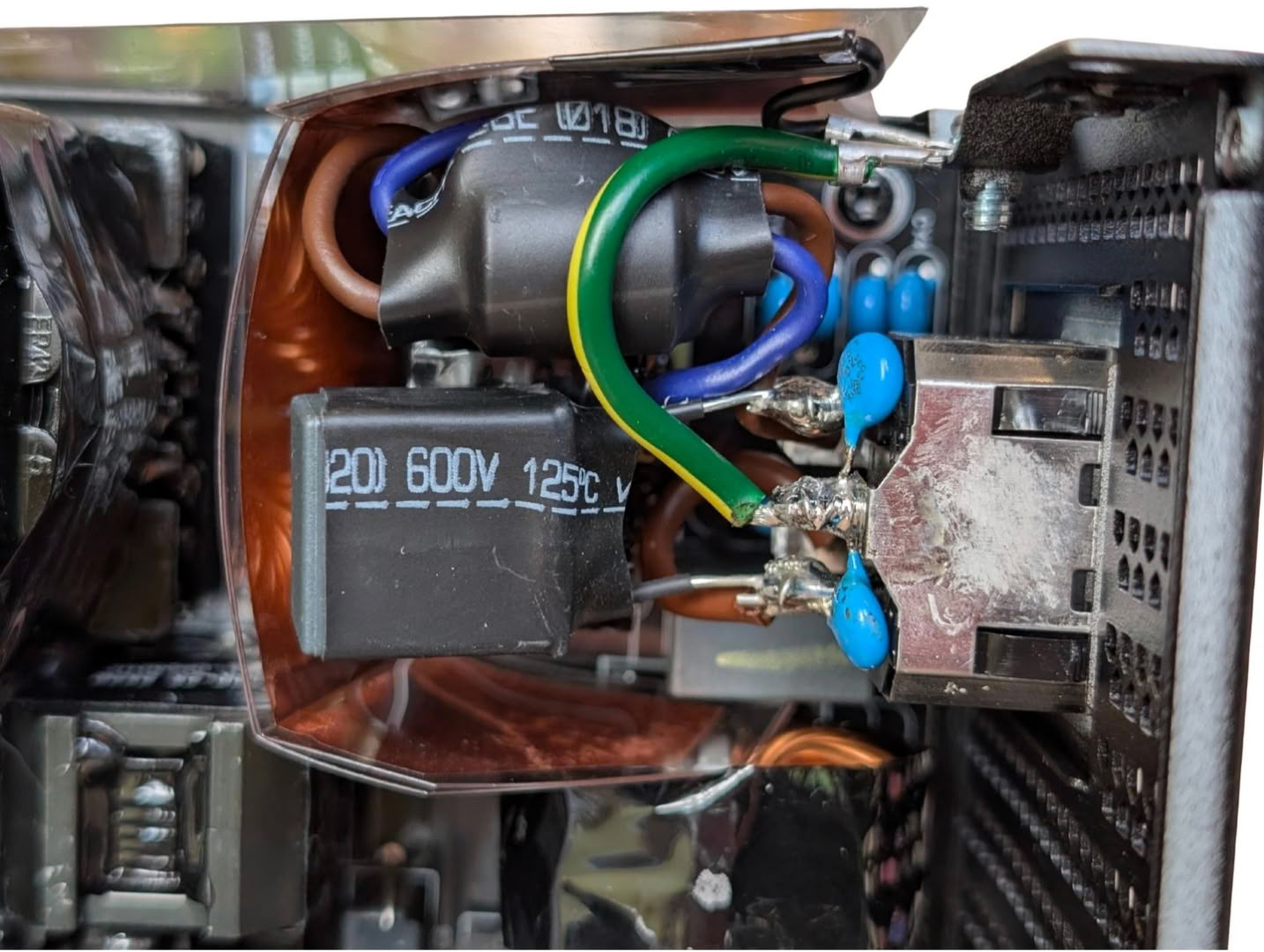
The EMI suppression is more than adequate. The power connector has two Y capacitors soldered directly to the terminals for L and N to GND, and four more on the main PCB just under. There is an X capacitor soldered across L and N, and another on the board below. There is also a ferrite core with L and N wrapped around it just after the power connector. A wide grounded copper strip is wrapped around the AC filter components, to prevent EMI from the main switching components getting into the AC waveform.
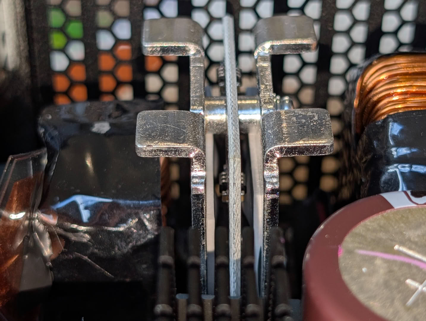
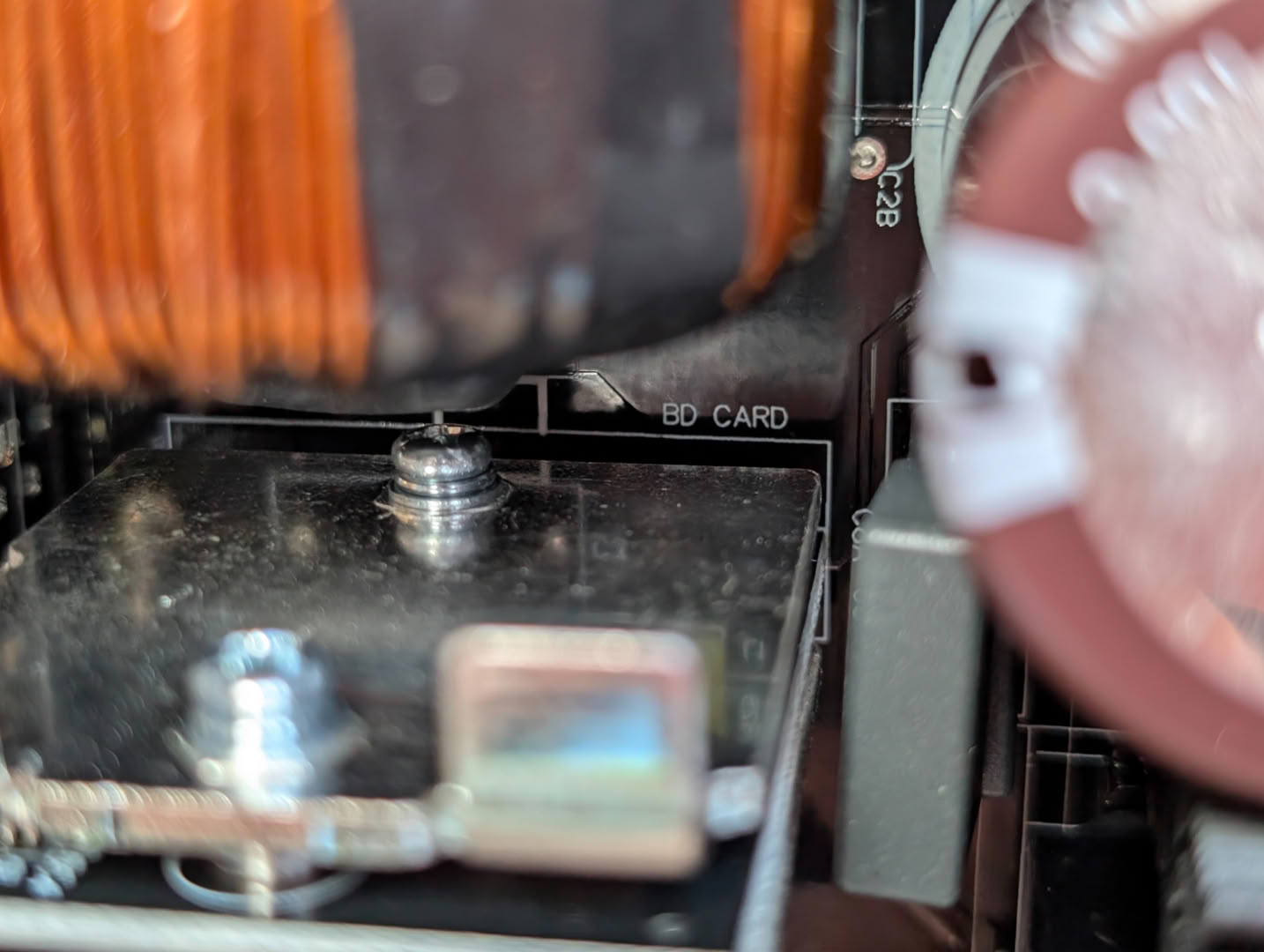
BD stands for Bridge Diode here, with the rectifier components sandwiched between heatsinks and pads.
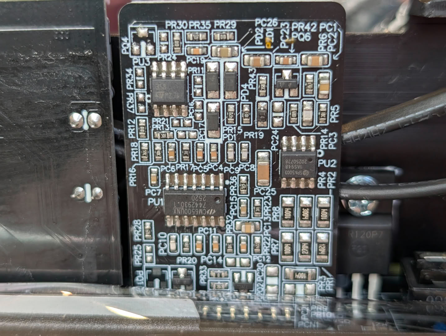

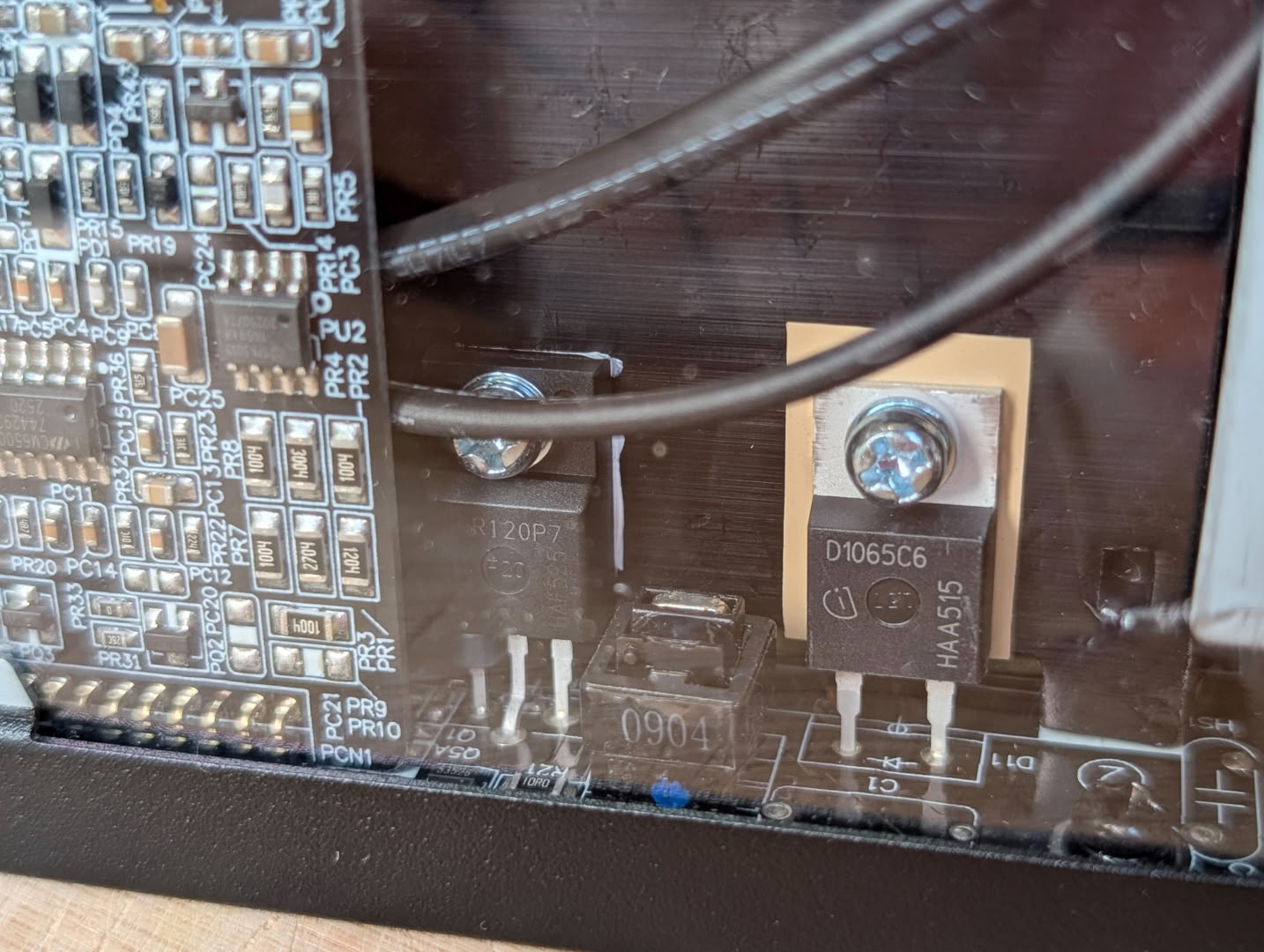
Power factor correction is being handled by a CM6500UN 1 MHz controller alongside these TO-220 package components on the heatsink.
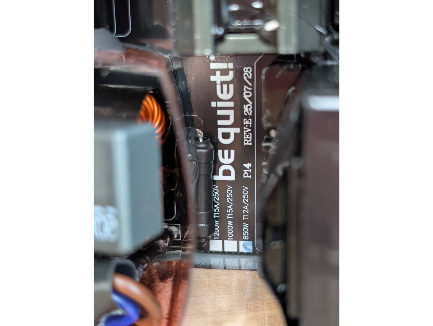
The silkscreen markings show us that this same PCB is used up to the 1200 W variant. This is good news for our 850 W model, as the board traces, connections and thermal design will all be suitable to support much higher power, thus there will be very minimal losses across them.
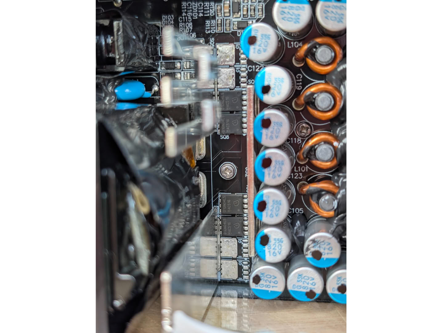
Often with a shared PCB like this there will simply be some missing parallel components such as mosfets, tweaks to the protection/monitoring circuitry, and perhaps thinner gauge wire used on the transformers and inductors (but chances are this remains constant across models). This photo shows the missing mosfets that would be fitted to the higher power models.
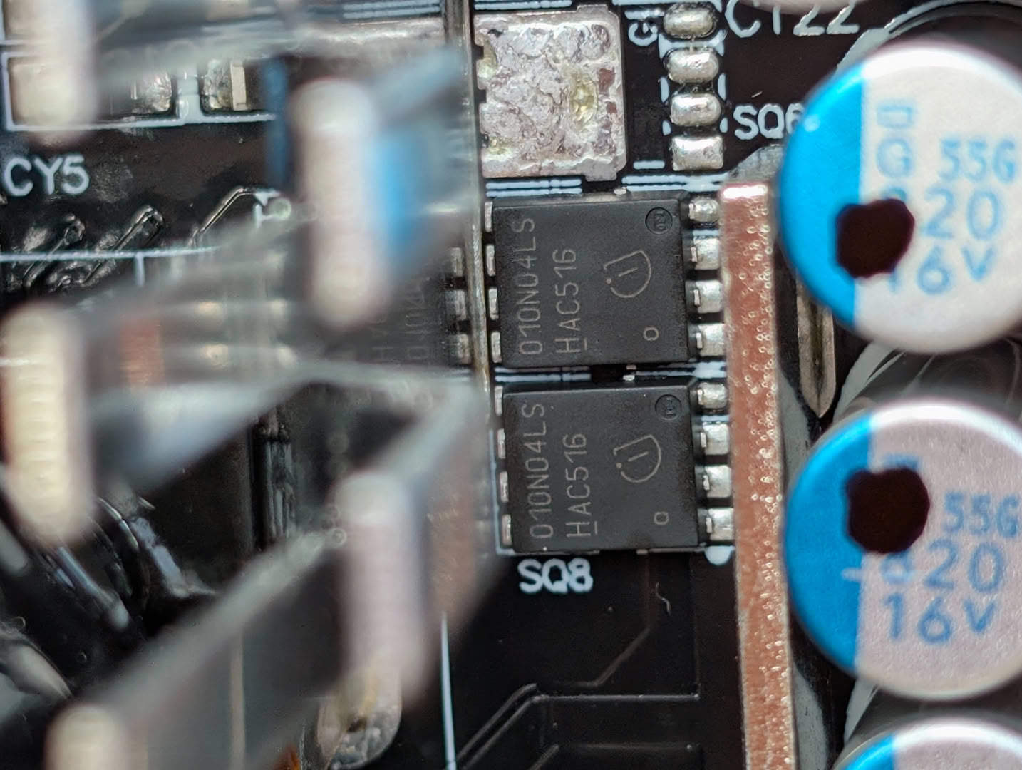
The mosfets used for the 12v rail are the Infineon OptiMOS™ Power MOSFET BSC010N04LS, 40 V 206/296 A at 25C/100C, 1mΩ of Rds and able to dissipate 167 W. Four out of a possible eight are used here for the 850 W model.
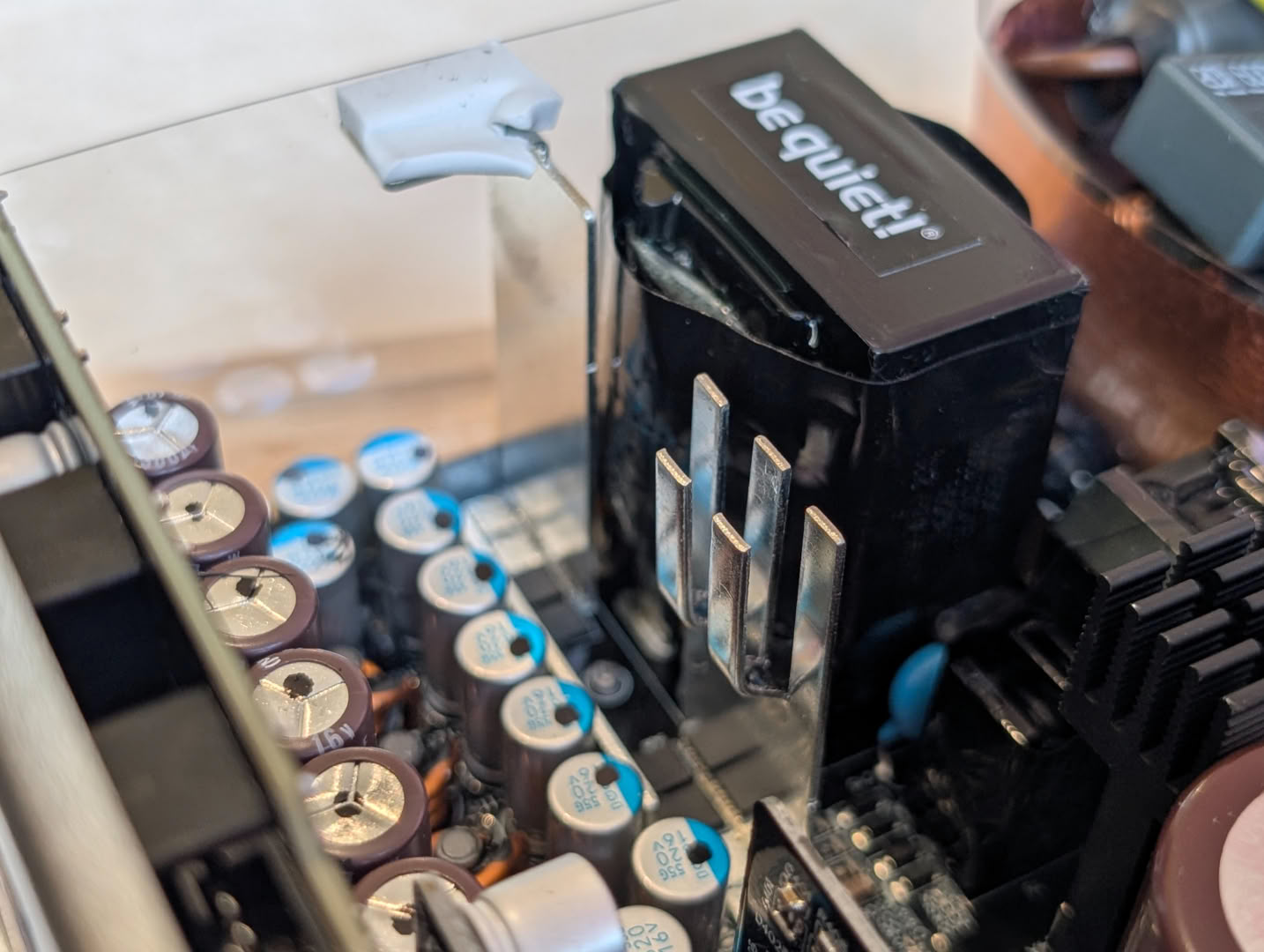
Heat is wicked away from the mosfets by the PCB itself, and by these basic finned heatsinks soldered to the main drain trace.
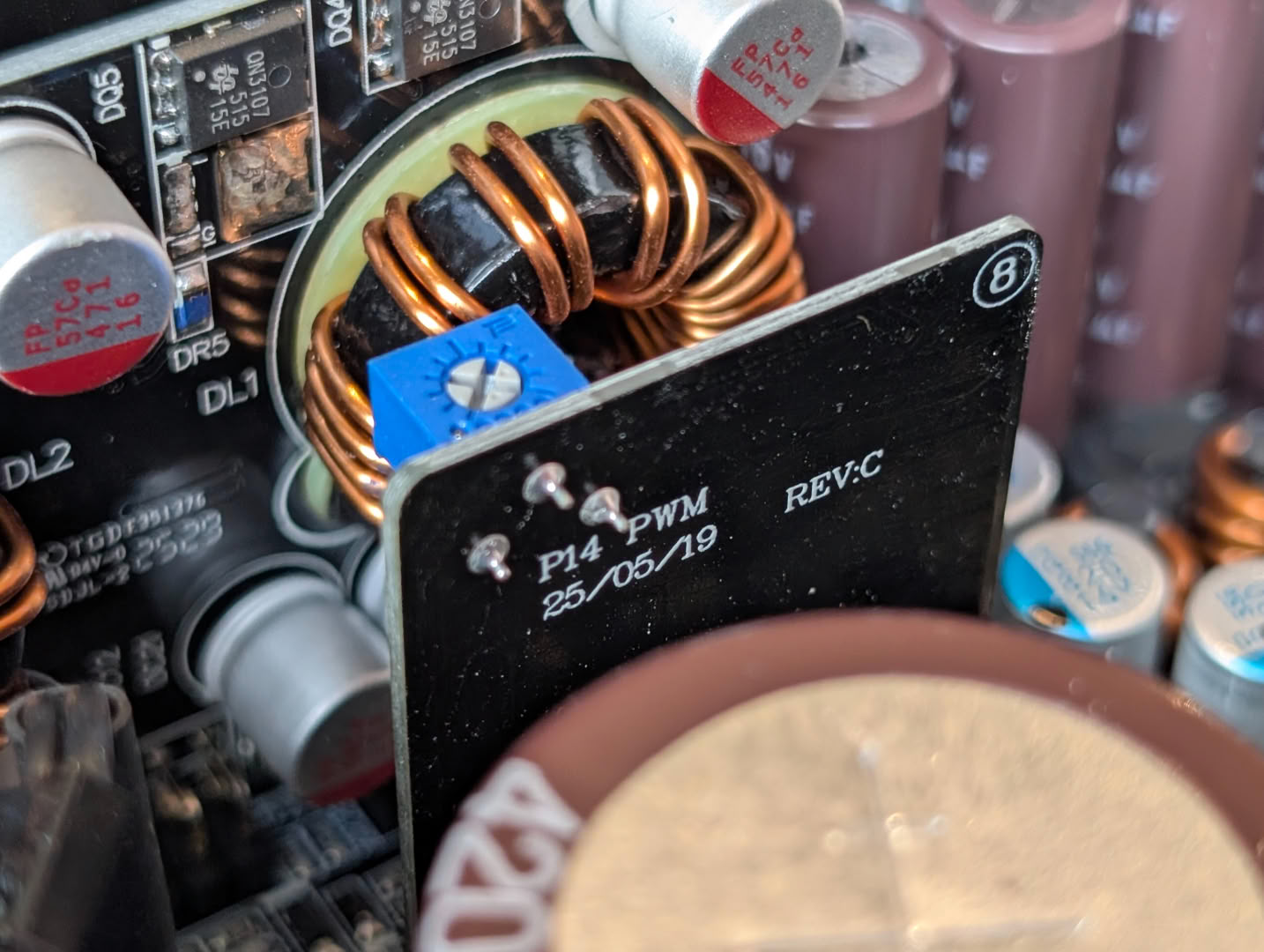
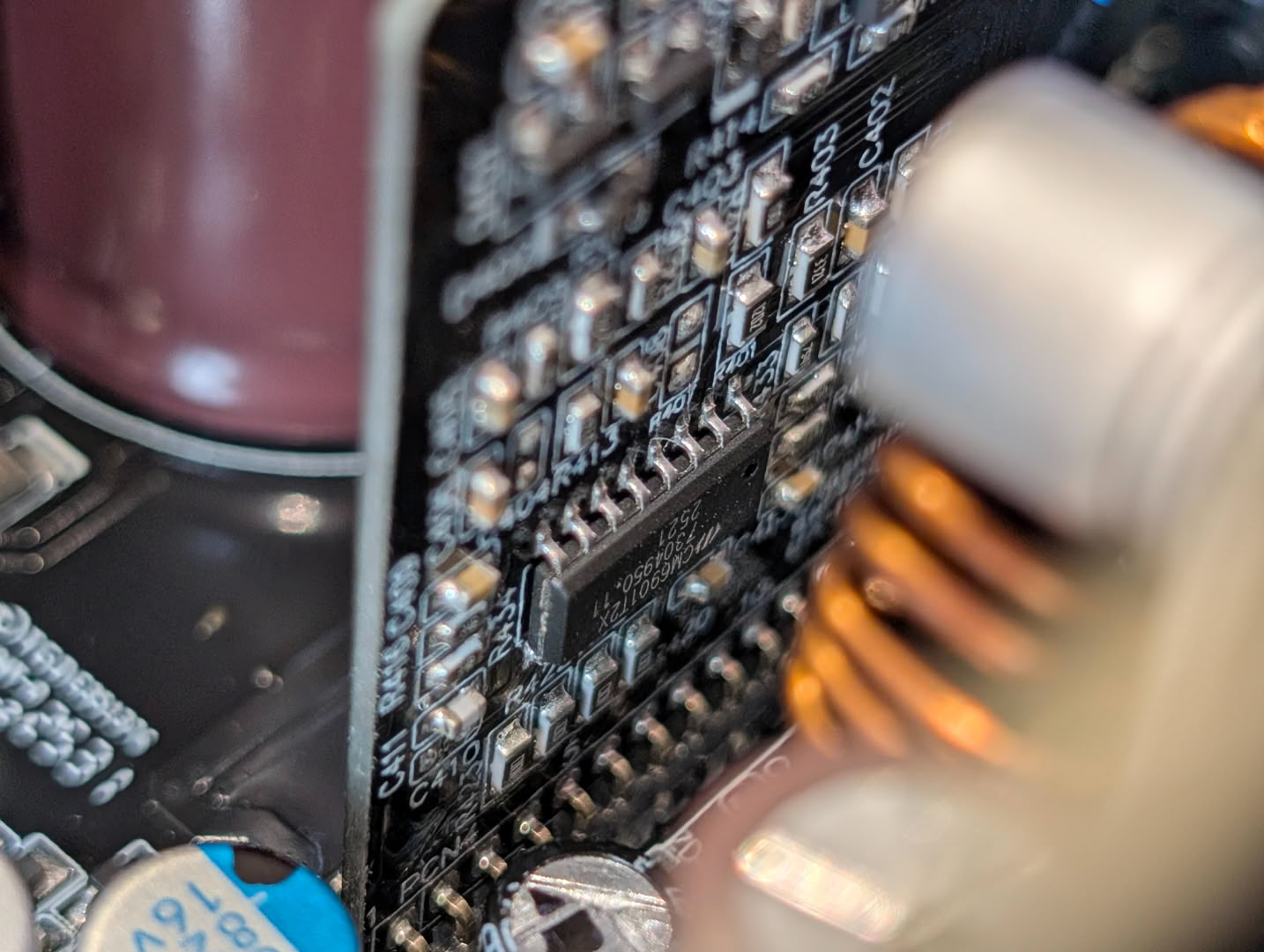
Driving the mosfets is this PWM card, with a CM6901 at the heart of it. It is unclear without further investigation what the potentiometer here does, perhaps voltage or frequency adjustment... best leave it alone.
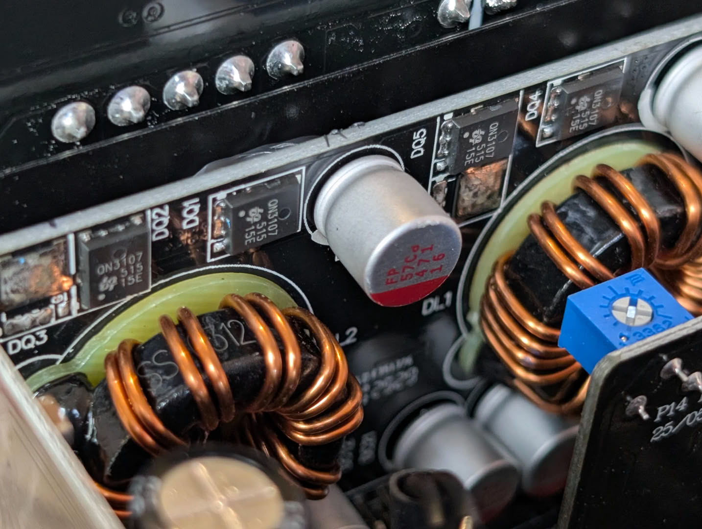
There is a daughterboard responsible for stepping down to the lower voltage rails, running QN3107M6N mosfets and inductors.
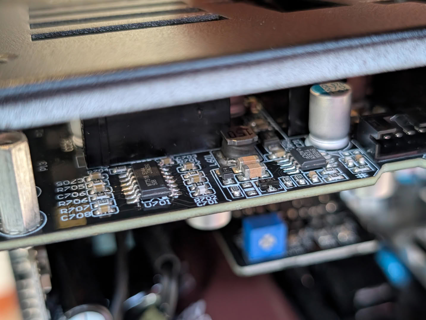
The WT7518 supervisor is hidden away on the output connector board, alongside a TPS54231 variable step-down converter, likely being used to regulate fan speed.
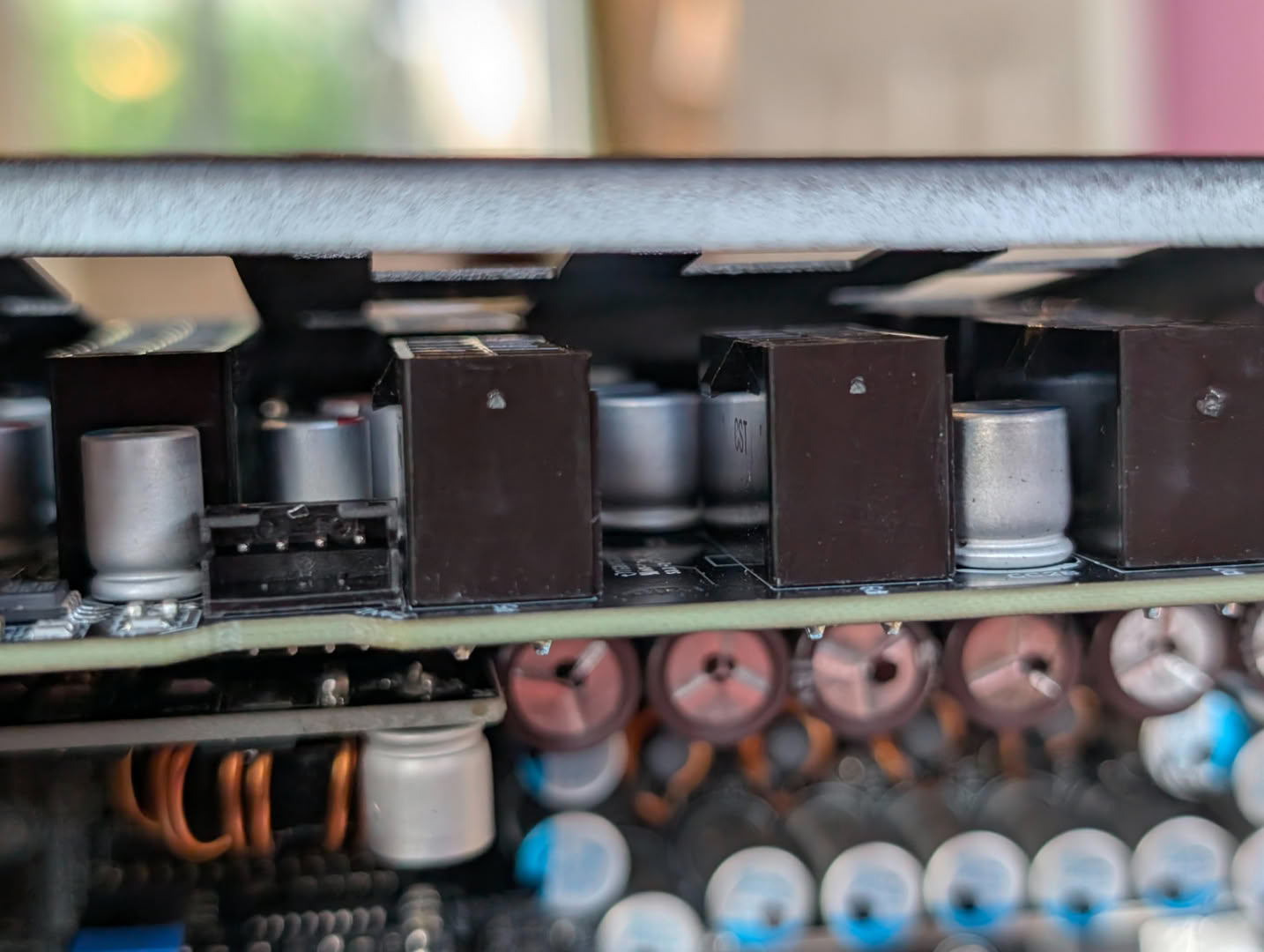
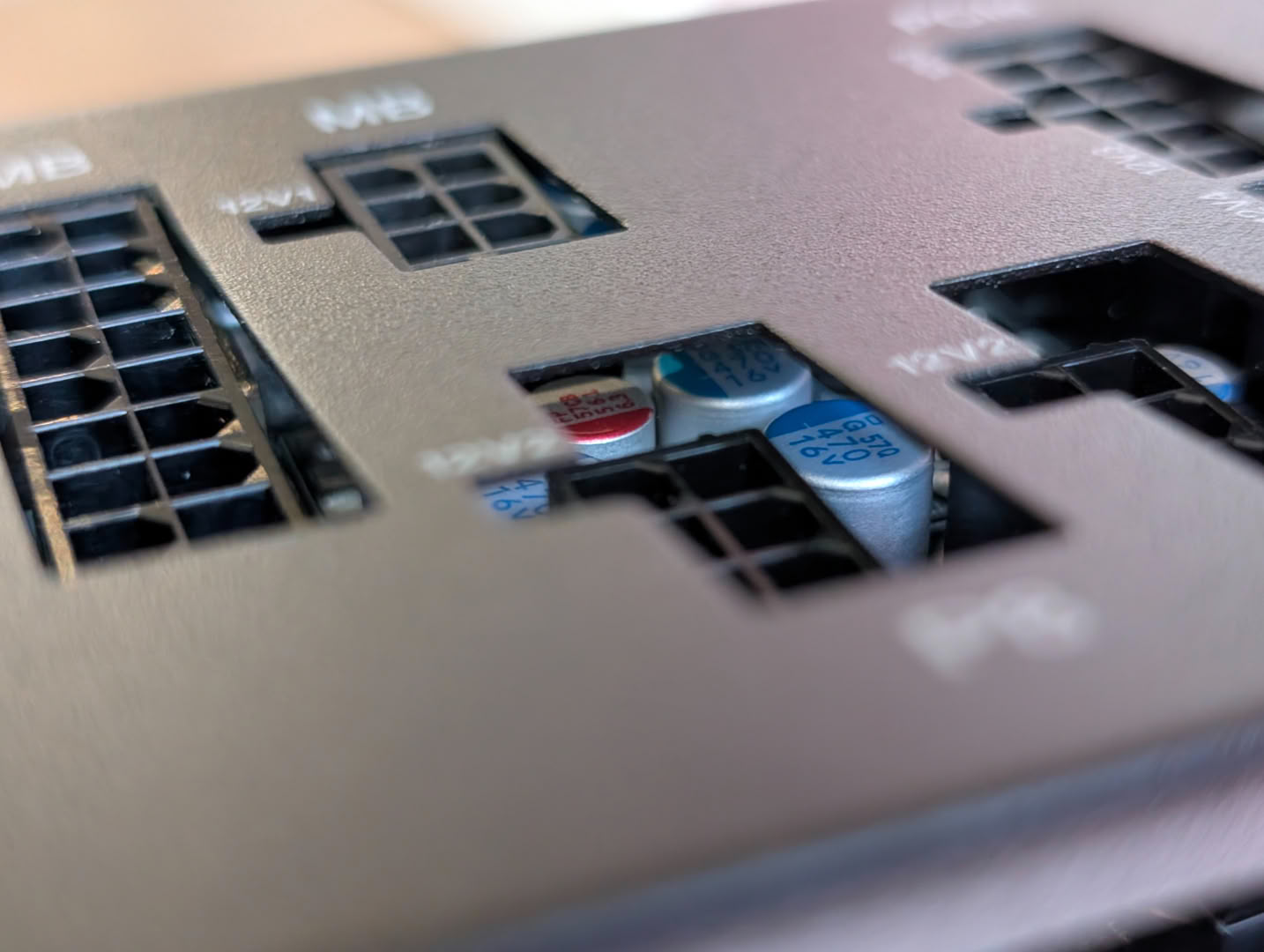
Plenty of smoothing caps can be found directly next to the power connectors themselves.
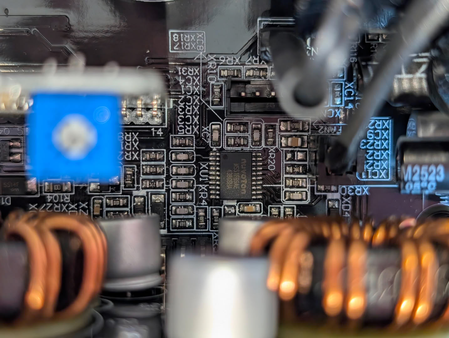
There is an MS51FB9AE 8-bit microcontroller situated near the PWM and step-down cards. The 0-RPM and OCK switches are connected nearby, so this will be handling the changes required to the main circuit when these modes are set. It may also be controlling the PWM on-state, listening out for voltage/current sense and protection signals from elsewhere in the circuit.
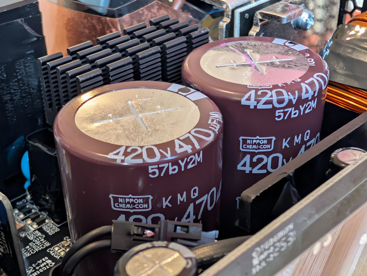
The main bulk capacitors are Nippon Chemi-Con 420 V 470 uF 105C rated.
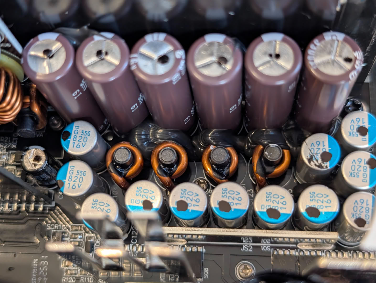
There are dedicated final output filter inductors for each of the four 12 V rails.
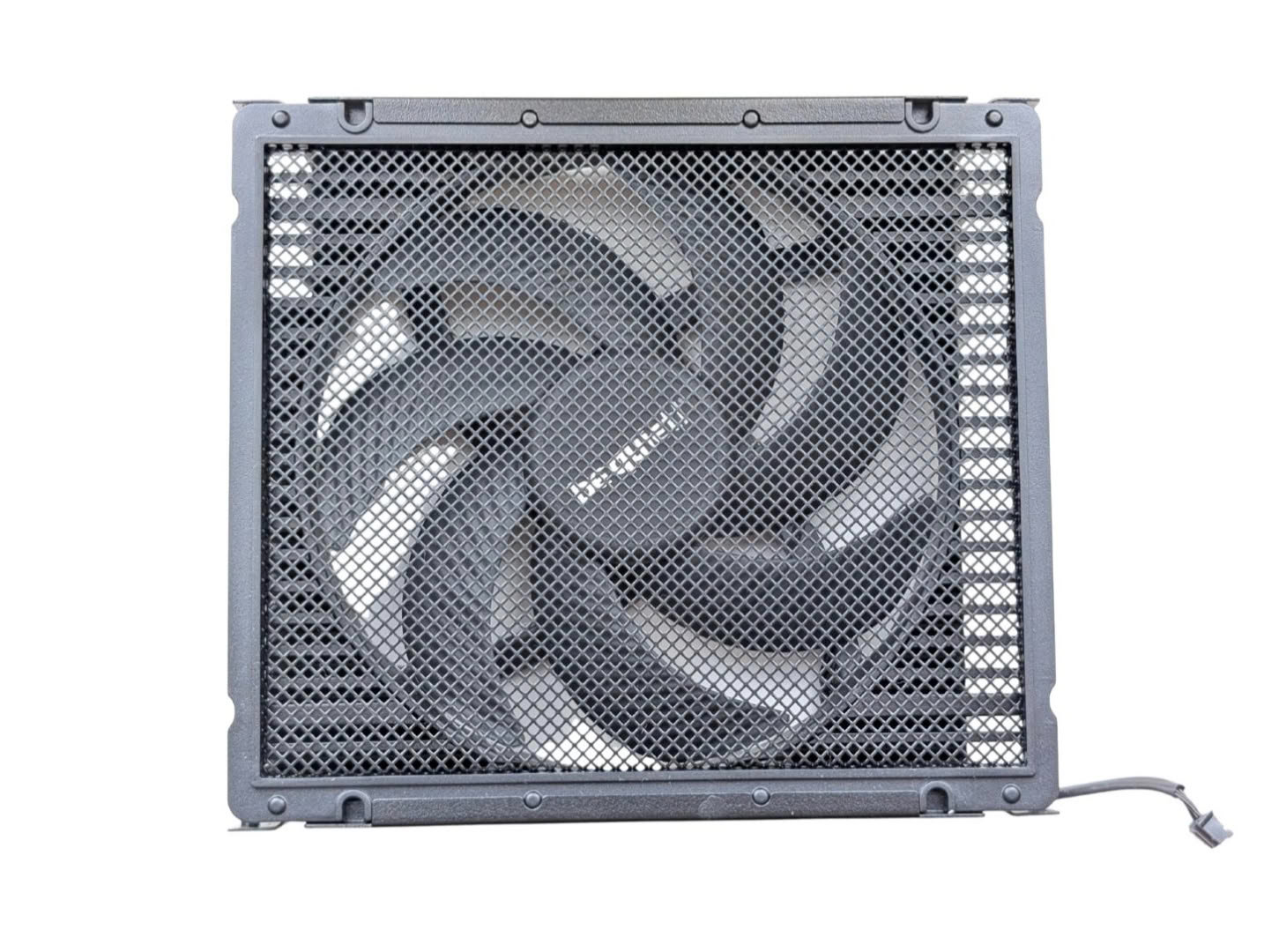
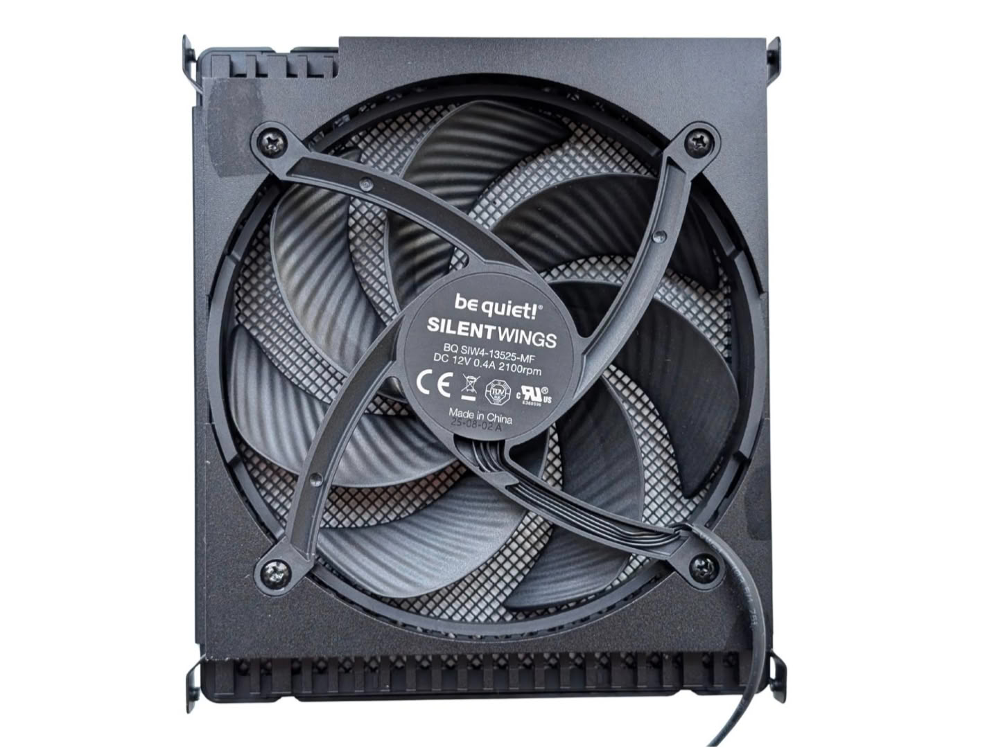
The unique 135 mm Silent Wings fan is frameless, and features a 6-Pole Fan Motor and a Fluid-Dynamic Bearing.
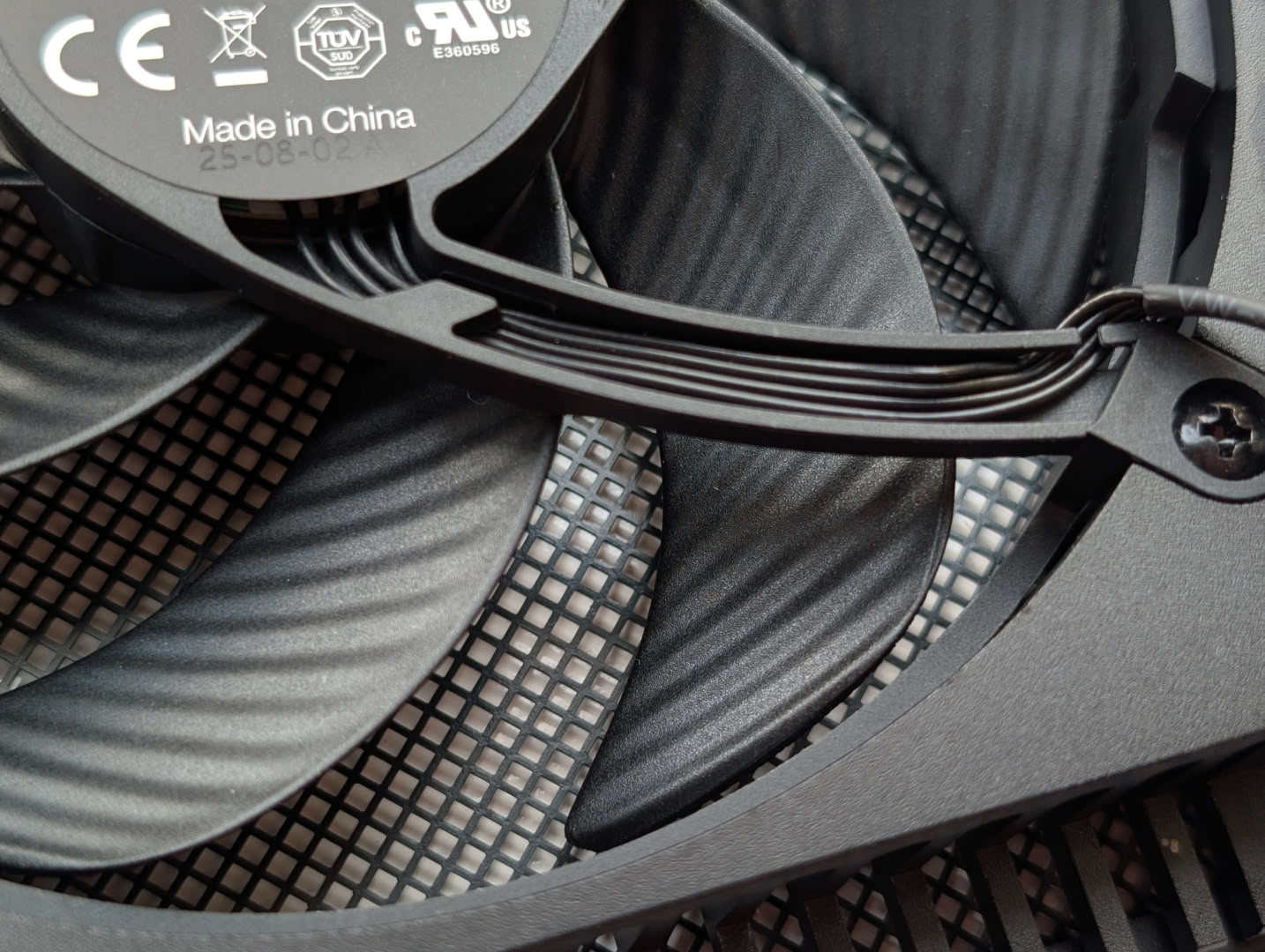
The blades have a rippled design in order to aid smooth airflow, fewer vortices and quieter operation.
The overall build and assembly quality is exceptional, with nothing loose or haphazard, and the soldering quality is great.
Nov 21st, 2026 04:43 PST
change timezone
Latest GPU Drivers
New Forum Posts
- WarpCoreBench scores! (88)
- What's your latest tech Freebie? (86)
- TPU's Nostalgic Hardware Club (22179)
- [Poll] 12V-2x6 Connector Protection: What Are You Using? (WireView / Ampinel / Equalizer / Other / Nothing) (50)
- UPS what one to get? (1)
- Anthrophics IPO (28)
- RX 9000 series GPU Owners Club (2252)
- Windows 11 General Discussion (7743)
- Without Jensen, PC gaming will be (52)
- Zen 3 IF/IMC degradation (242)
Popular Reviews
- Microsoft Surface Laptop Ultra Review - The Next-gen Arm Laptop
- Ugreen NASync DXP4800 GT Review
- Corsair RM1200e (Second Generation) Review
- Pulsar Office Tour & First Look at P1 Dual-Sensor Mouse
- Upcoming Hardware Launches 2027 (Updated Nov 2026)
- Acemagic Retro X3 Review
- Biwin Black Opal NV7400 2 TB Review
- AMD Ryzen 7 9800X3D Review - The Best Gaming Processor
- AMD Zen 6 Technical Deep Dive
- Chieftec Iceberg PRO 360 DARK Review
TPU on YouTube
Controversial News Posts
- NVIDIA Co-Founder and CEO Jensen Huang Officially Resigns (491)
- Report: Jensen Huang Eyes NVIDIA Comeback (257)
- Open Letter Asking NVIDIA to Reinstate Jensen Huang Passes 115,000 Signatures (184)
- OpenAI CEO Argues Home PCs Waste the World's Limited DRAM Supply (152)
- NVIDIA Launches Investigation Into Jensen Huang's Relationship With Suspected Chinese Spy (136)
- Intel "Raptor Lake Next" 16-Core and 20-Core CPUs Surface (130)
- Legendary Game Studio BioWare Shuts Down Following EA Layoffs (104)
- NVIDIA GeForce RTX 50-Series Scheduled for up to $500 Price Hike This Week (89)