 0
0
Corsair RM Series 850 W Review
Voltage Regulation, Hold-up Time & Inrush Current »A Look Inside & Component Analysis
Before reading this page, we strongly suggest a look at this article, which will help you understand the internal components of a PSU much better. Our main tool for the disassembly of the PSU is a Thermaltronics TMT-9000S soldering and rework station. It is of extreme quality and is equipped with a matching de-soldering gun. With such equipment in hand, breaking apart every PSU is like a walk in the park!
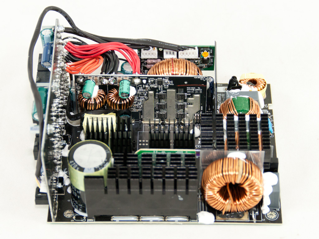


The OEM of every new RM unit, except for the 750 W and 850 W models, is Corsair's favorite manufacturer, CWT (Channel Well Technology). The two aforementioned units are, according to various sources on the net, made by Chicony Power Technology; however, the platform of this unit reminds us of CWT's PUQ (G), though there are some significant differences between the two. For starters, Chicony's platform uses much larger heatsinks, and the DC-DC converters in the secondary side are not installed on the modular PCB but on a large vertical daughter-board, along with the mosfets that generate the +12V rail. They probably thought that having all rails on the same PCB is more efficient because it allows the +12V rail to directly feed both DC-DC converters generating the minor rails.
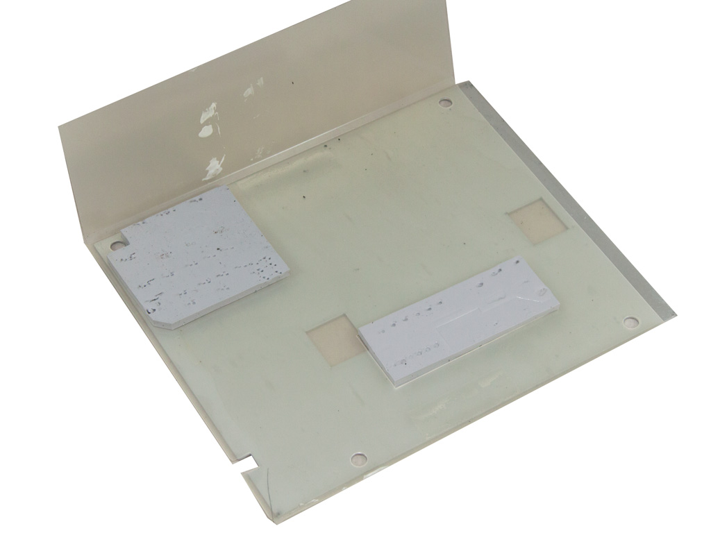
The distance the power cables have to cover until they reach the modular PCB would then be small, keeping energy losses at a bare minimum. All in all, the design looks good. The four main switchers caught our attention first, but we will elaborate on those in the following paragraphs. We also noticed the very large heatsinks used in the primary side and the metal plate covering the whole solder side of the main PCB. This metal plate apparently plays a key role in removing the heat the components on the main PCB produce, allowing the PSU to operate in passive mode for prolonged periods of time.
The first part of the transient filtering stage starts at the AC receptacle and only includes a couple Y caps. The second part, located on the main PCB, consists of two X and two Y caps, three CM chokes, and an MOV.


The two parallel bridge rectifiers are bolted to a large dedicated heatsink.

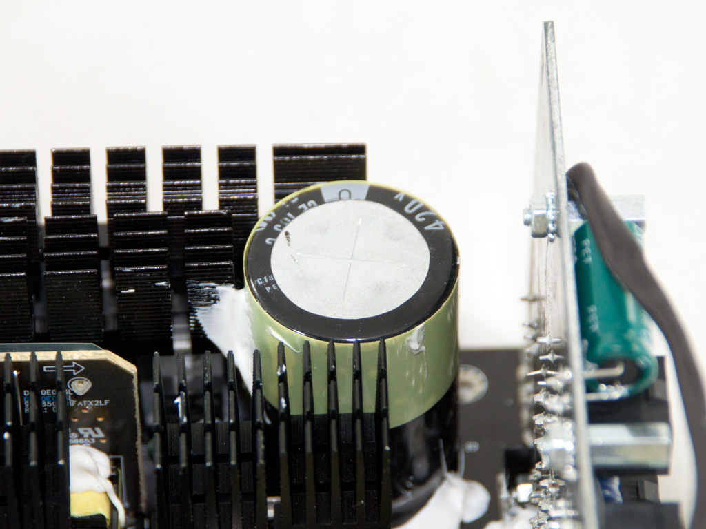

Three mosfets and a CREE C3D08060A boost diode are used in the APFC. The bulk cap is provided by Panasonic (420 V, 560 μF, 105°C).
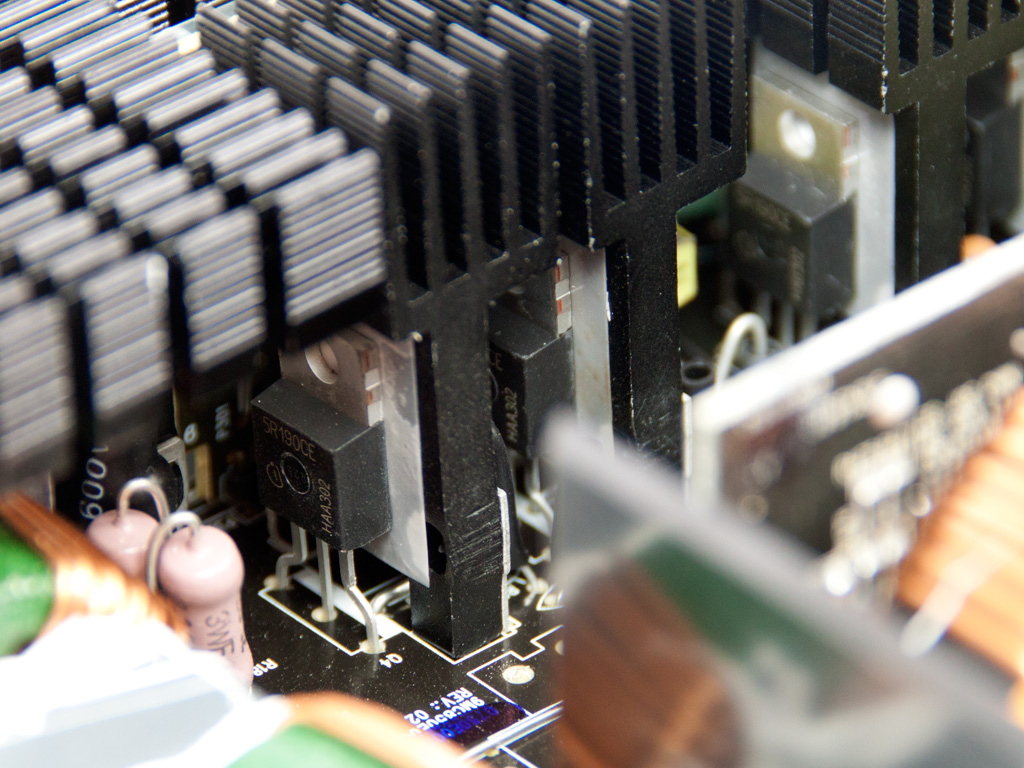

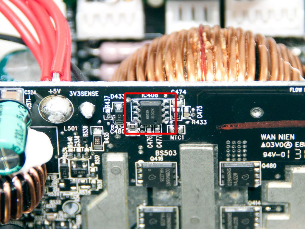
Two heatsinks hold a pair of Infineon IPP50R190CE fets each. Without checking the PWM controller, we can safely assume that a full bridge topology is used, but the small daughter-board behind one of the above heatsinks hosts a combo PFC/PWM CM6802 IC, and this controller doesn't support a full bridge topology. Something else is going on here; each pair of mosfets is apparently controlled/seen as a single fet by the PWM controller.
We had to remove the main transformer to take a good look at the vertical PCB holding all active components of the secondary side.
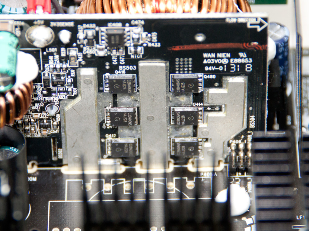
There is no heatsink in the secondary side, only a large daughter-board that holds all mosfets (six Infineon BSC028N06NS) that rectify the +12V rail and both VRMs (Voltage Regulation Modules) generating the minor rails. Three metal bars are responsible for transferring current to/from the above fets. They provide earth and help with heat dissipation. We also spotted an APE6019 synchronous rectifier (SR) driver IC at the very top-right of this board; it drives the +12V fets.

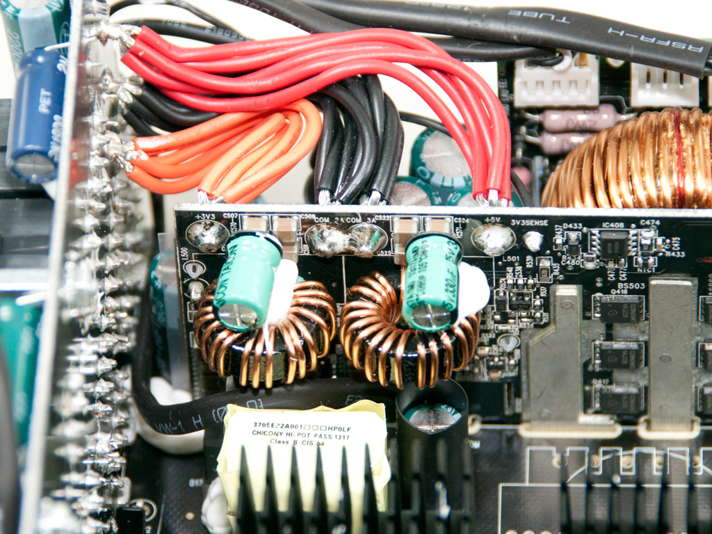

The VRMs use two Taicon electrolytic caps for ripple filtering. All the other caps in the secondary side are by Ltec. Corsair's cap choice definitely isn't the best. Lowering production cost was apparently a prerogative, yet the warranty for this product is still set to five years. Corsair must have been pretty confident to go with Ltec instead of Teapo or better.


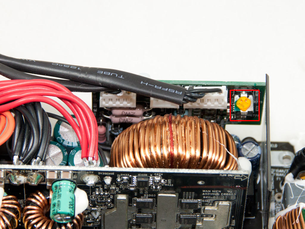
This board holds the supervisor IC we were unable to identify. It also features a potentiometer which we avoided tampering with, though it was a tempting.


The front of the modular PCB hosts several electrolytic Ltec caps, for some extra ripple filtering. This is a typical move when there is no space on the main PCB for any more filtering caps, or when ripple is higher than expected and the techs decide to lower it after the main PCB has already hit the production line.
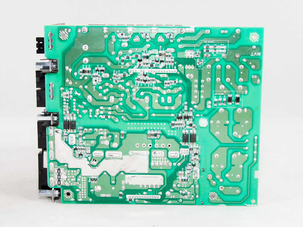
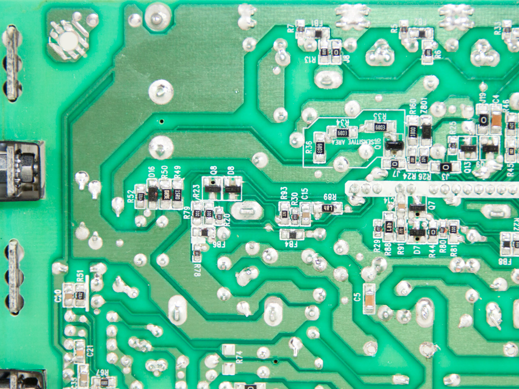


Soldering quality isn't the best we have seen. The production line probably needs some time to hit optimal quality levels. CWT implementations are clearly superior in this area, so Chicony has some catching up to do. The large metal bar shown on the fourth of the above photos is used to transfer earth to the modular panel, while the smaller bar is used by the +12V rail. We also spotted three current sense resistors right in front of the +12V pads on the modular PCB.


The cooling fan is, according to Corsair, designed to operate quietly, and we have no reason to doubt them. We will obviously check our dB meter readings to be sure! This fan's model number is NR135L (12 V, 0.22 A). Corsair doesn't provide any information on the type of bearings it uses (Corsair informed us after the review was posted that it uses rifle bearings).
Jul 24th, 2025 19:55 CDT
change timezone
Latest GPU Drivers
New Forum Posts
- Current Sales, Bundles, Giveaways (10348)
- Lexar NM790 (4TB) made my PC go back to Windows XP days, since it caused my PC to be SO slow and laggy! (22)
- What's your latest tech purchase? (24357)
- B580 tanks performance with low end CPUs (215)
- 14900k high voltage (43)
- R9 7900X - 5070Ti - Lags / Stuttering (12)
- Windows 10 Vs 11, Which one to choose? (230)
- Solidigm NVMe Custom Modded Driver for All NVMe Brands SSDs & Any NVMe SSDs (233)
- VMware Workstation is now free for everyone (29)
- I'm not really impressed with the AMD Z2 extreme processor (2)
Popular Reviews
- Noctua NF-A12x25 G2 PWM Fan Review
- MSI MPG B850I Edge Ti Wi-Fi Review
- UPERFECT UMax 24 Review
- Cougar OmnyX Review
- TerraMaster F4-424 Max Review - The fastest NAS we've tested so far
- Thermal Grizzly WireView Pro Review
- Sharkoon OfficePal C10 Review - Affordable and Decent
- VAXEE XE V2 Wireless Review
- Upcoming Hardware Launches 2025 (Updated May 2025)
- Razer Blade 16 (2025) Review - Thin, Light, Punchy, and Efficient
TPU on YouTube
Controversial News Posts
- Some Intel Nova Lake CPUs Rumored to Challenge AMD's 3D V-Cache in Desktop Gaming (140)
- AMD Radeon RX 9070 XT Gains 9% Performance at 1440p with Latest Driver, Beats RTX 5070 Ti (131)
- AMD's Upcoming UDNA / RDNA 5 GPU Could Feature 96 CUs and 384-bit Memory Bus (119)
- NVIDIA GeForce RTX 5080 SUPER Could Feature 24 GB Memory, Increased Power Limits (115)
- NVIDIA DLSS Transformer Cuts VRAM Usage by 20% (99)
- AMD Sampling Next-Gen Ryzen Desktop "Medusa Ridge," Sees Incremental IPC Upgrade, New cIOD (97)
- NVIDIA Becomes First Company Ever to Hit $4 Trillion Market-Cap (94)
- Windows 12 Delayed as Microsoft Prepares Windows 11 25H2 Update (92)