 6
6
CORSAIR STRAFE RGB MK.2 Keyboard Review
Driver »Disassembly
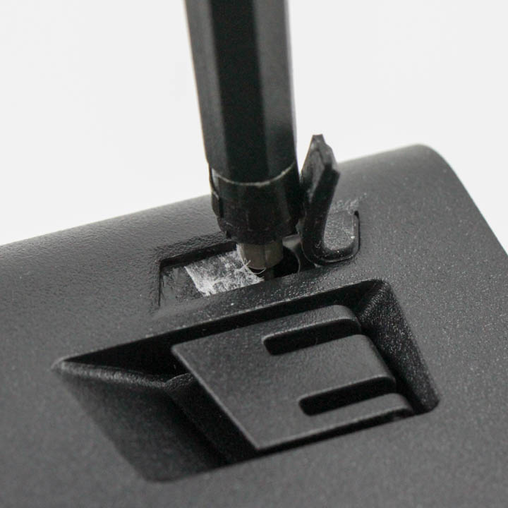

There is quite a lot to see here, and disassembly of the keyboard begins with the removal of 13 Phillips head screws on the bottom holding the two case pieces together. After this, you get the dubious pleasure of using a thin, flat object to pry apart the two pieces that are held together via multiple interlocking plastic tabs as seen above.
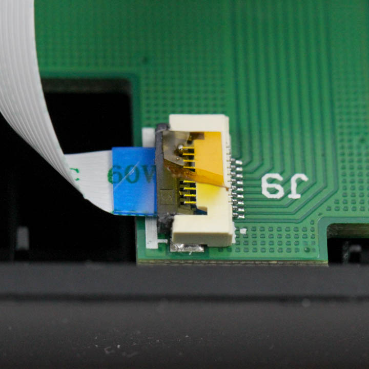
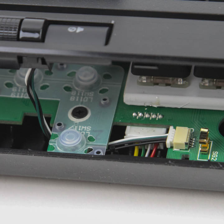

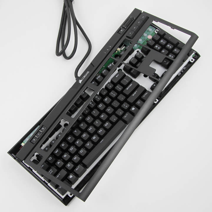
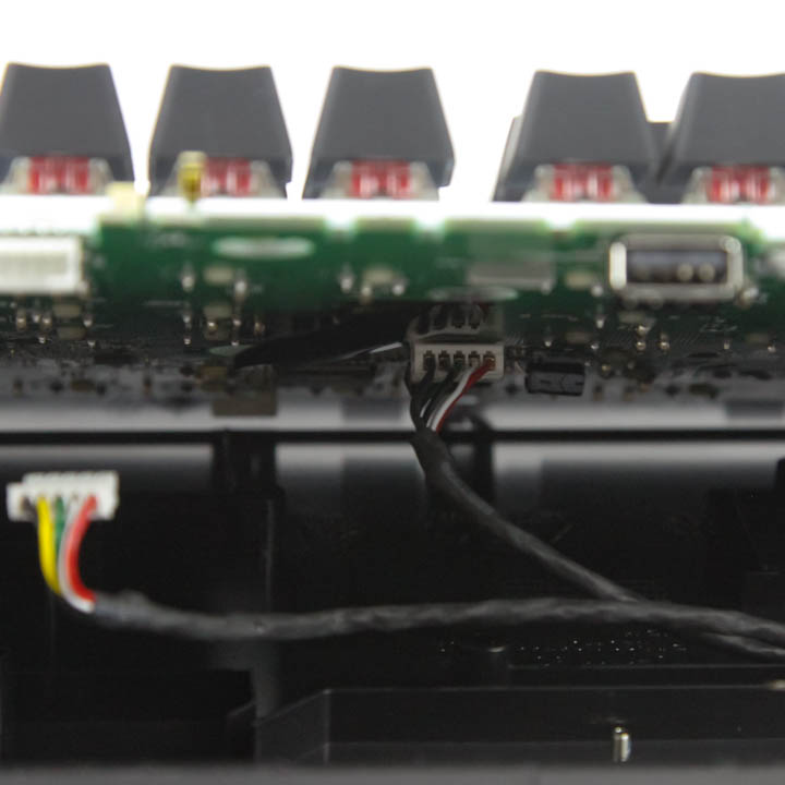
There are still two cables connecting the top panel piece to the PCB that need to be removed before full separation, and here, you also have to be careful. At least on my sample, the middle cable that connects to the LEDs under the CORSAIR logo on the top was taped into a connector, and the actual holding clip was broken out of the box. The tape was thus the only thing keeping it in place, and putting this back together was a real pain as it took me over 30 minutes. The other cable connects the daughter PCBs to the main PCB, which helps with the additional keys we saw before, and it is easy enough to remove, but you may have to loosen the screws on the main PCB to provide enough flex to move the connector under and over as seen above. Once done, we can take a closer look at the top case panel, which confirms an ABS plastic composition as well as membrane switches for the other keys alongside the smooth scroll wheel for volume control and LEDs throughout for more lighting.


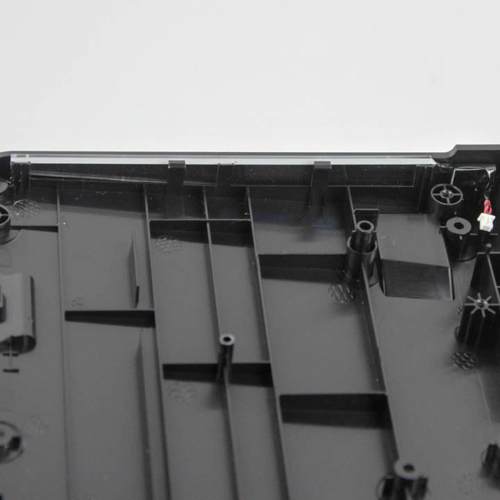
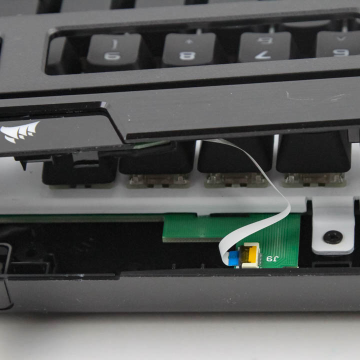
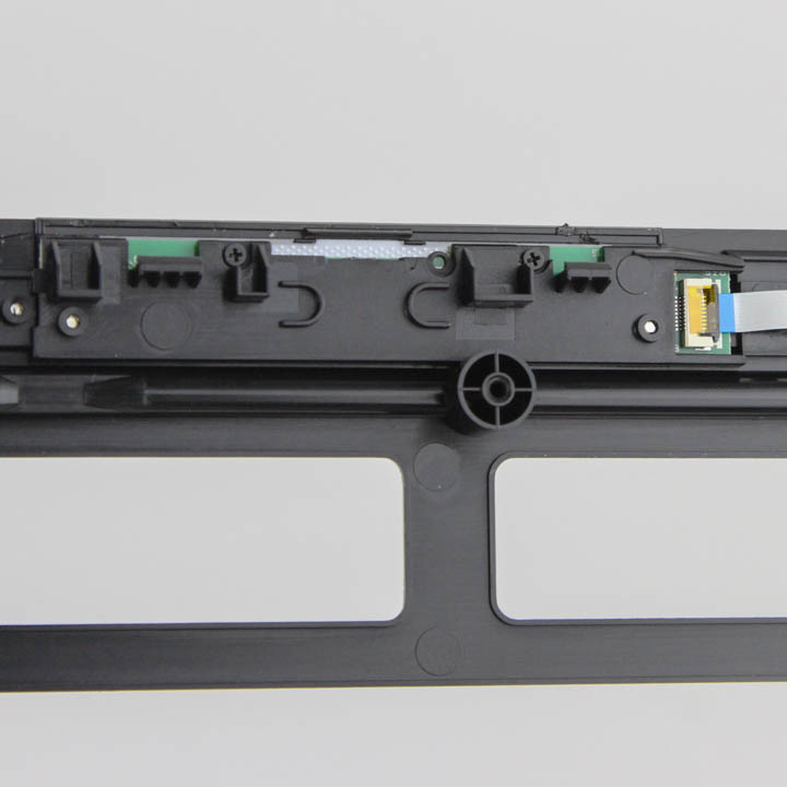
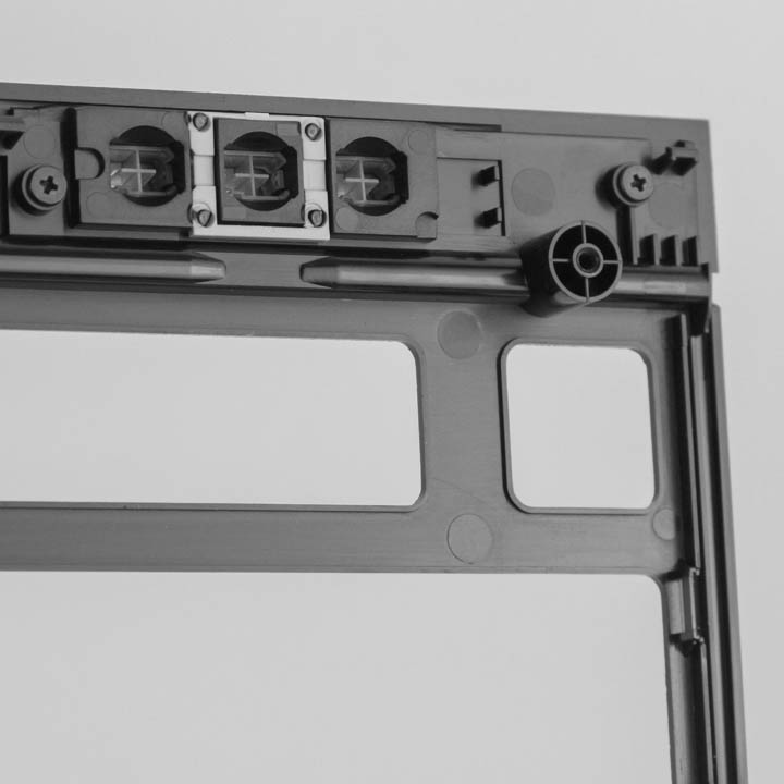
There are more screws holding the main PCB in place on the bottom case panel, and removing them only means there is enough flex to now disconnect more cables. To begin with, there are two side plates that have a cable each for lighting, and then there are the two cables coming off the keyboard cable and going on to internal USB connectors underneath. With all four cables disconnected, we can finally separate and remove the bottom panel piece also composed of ABS plastic.
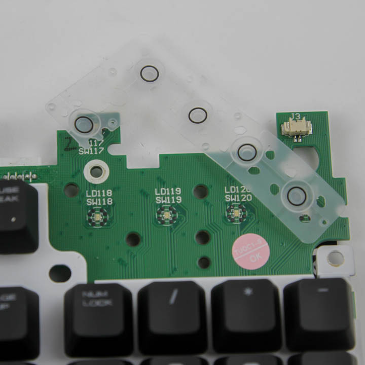
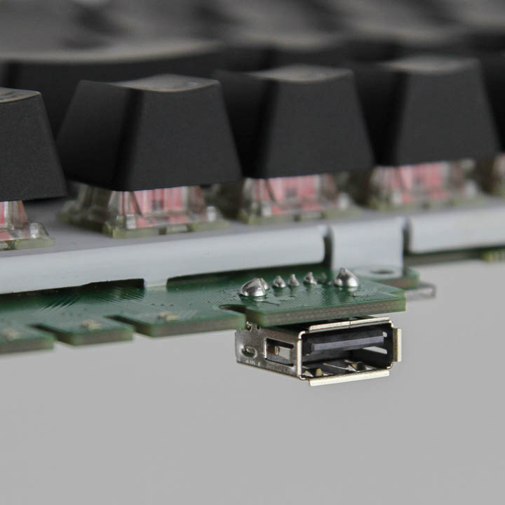

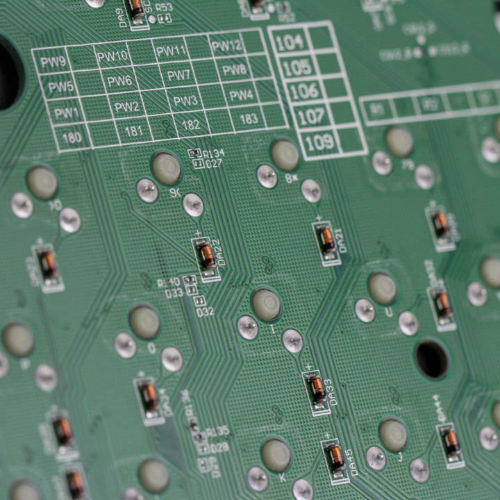
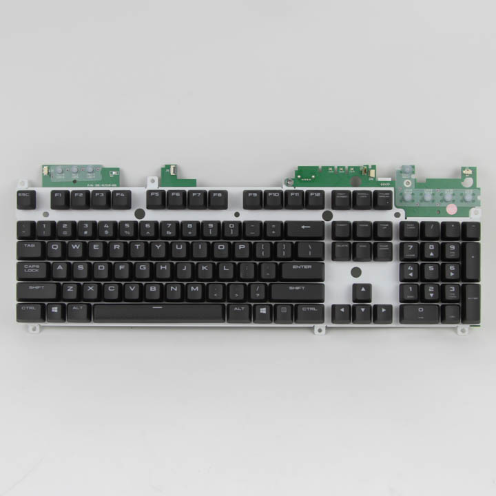
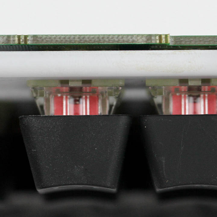
We see a stainless steel plate added for structural integrity, and it has been given a white color to better reflect light off the surface, which enhances the keyboard's lighting in person. The primary PCB is extended at its top corners to accommodate the extra keys that use membrane switches, as we see above, and the rest of the keyboard utilizes Cherry MX RGB switches. The solder quality is really good on the underside, with definite signs of machine assembly. The USB pass-through port does appear to be hand-assembled and not done as well with some relatively ugly and large solder balls.
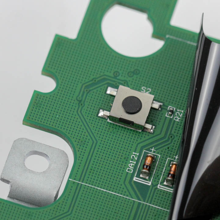
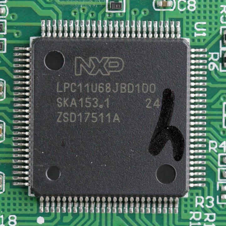

Underneath one of the black pieces of electrical insulating tape is a secret hardware reset button, and it can be accessed without keyboard disassembly by looking out for a small hole by the keyboard feet when raised. Powering the Corsair STRAFE RGB MK.2 is an NXP LPC11U68JBD100 32-bit ARM Cortex-M0+/M0 Cores-based USB microcontroller with 256 KB on-board flash memory and 36 KB SRAM. There is also a Macronix MX25L6433 8 MB flash memory module to store all the pre-programmed functions alongside some 100µF polymer capacitors. All the components, including the switches, LEDs, and capacitors, are soldered to a multi-layered PCB.
Before we move on, be advised that disassembly will void the warranty and that TechPowerUp is not liable for any damages incurred if you decided to go ahead and do so anyway.
May 16th, 2024 04:36 EDT
change timezone
Latest GPU Drivers
New Forum Posts
- Immortals of Aveum deserves a second chance, the new free demo has convinced me. (48)
- EULA in Games (10)
- Double radiator setup with GPU fans on top (5)
- What's your latest tech purchase? (20532)
- Apparently Valve is giving refunds on Helldivers 2 regardless of hour count. Details inside. (108)
- AM5 boot times improve RADICALLY with memory context restore enabled (69)
- MSI Z370 SLI PLUS + i9 9900k bad perfomance. (3)
- have LGA 1155 motherboard which xeon processor will fit ? (15)
- Ubuntu 24.04 LTS released (29)
- NVcleanstall error (3)
Popular Reviews
- Homeworld 3 Performance Benchmark Review - 35 GPUs Tested
- Enermax REVOLUTION D.F. X 1200 W Review
- Lofree Edge Ultra-Low Profile Wireless Mechanical Keyboard Review
- Upcoming Hardware Launches 2023 (Updated Feb 2024)
- ZMF Caldera Closed Planar Magnetic Headphones Review
- AMD Ryzen 7 7800X3D Review - The Best Gaming CPU
- Corsair MP700 Pro SE 4 TB Review
- ASUS Radeon RX 7900 GRE TUF OC Review
- ThundeRobot ML903 NearLink Review
- Sapphire Radeon RX 7900 GRE Pulse Review
Controversial News Posts
- Intel Statement on Stability Issues: "Motherboard Makers to Blame" (267)
- AMD to Redesign Ray Tracing Hardware on RDNA 4 (227)
- Windows 11 Now Officially Adware as Microsoft Embeds Ads in the Start Menu (172)
- NVIDIA to Only Launch the Flagship GeForce RTX 5090 in 2024, Rest of the Series in 2025 (152)
- AMD Hits Highest-Ever x86 CPU Market Share in Q1 2024 Across Desktop and Server (137)
- AMD RDNA 5 a "Clean Sheet" Graphics Architecture, RDNA 4 Merely Corrects a Bug Over RDNA 3 (124)
- AMD's RDNA 4 GPUs Could Stick with 18 Gbps GDDR6 Memory (114)
- AMD Ryzen 9 7900X3D Now at a Mouth-watering $329 (104)