 8
8
Cougar GX-S 550 W Review
Ripple Measurements »Advanced Transient Response Tests
In these tests, we monitor the response of the PSU in two different scenarios. First, a transient load (10 A at +12V, 5 A at 5V, 5 A at 3.3V, and 0.5 A at 5VSB) is applied to the PSU for 200 ms while the latter is working at 20% load. In the second scenario, the PSU, while working at 50% load, is hit by the same transient load. In both tests, we measure the voltage drops the transient load causes using our oscilloscope. The voltages should remain within the regulation limits as defined by the ATX specification. We must stress here that these tests are crucial since they simulate transient loads a PSU is very likely to handle (e.g., booting a RAID array, an instant 100% load of CPU/VGAs, etc.). We call these tests "Advanced Transient Response Tests", and they are designed to be very tough to master, especially for a PSU with a capacity below 500 W.| Advanced Transient Response 20% | ||||
|---|---|---|---|---|
| Voltage | Before | After | Change | Pass/Fail |
| 12 V | 12.226V | 12.053V | 1.42% | Pass |
| 5 V | 5.078V | 4.957V | 2.38% | Pass |
| 3.3 V | 3.345V | 3.208V | 4.10% | Pass |
| 5VSB | 5.145V | 5.043V | 1.98% | Pass |
| Advanced Transient Response 50% | ||||
|---|---|---|---|---|
| Voltage | Before | After | Change | Pass/Fail |
| 12 V | 12.183V | 12.017V | 1.36% | Pass |
| 5 V | 5.046V | 4.923V | 2.44% | Pass |
| 3.3 V | 3.317V | 3.174V | 4.31% | Pass |
| 5VSB | 5.109V | 5.011V | 1.92% | Pass |
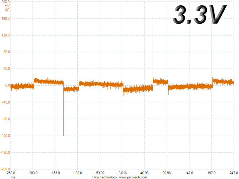
The PSU's low capacity doesn't help in these tests. The +12V rail deviates significantly in both tests, but still manages to keep its voltage above the nominal level when the transient load is applied. This is mainly due to the +12V rail's high initial voltage. The 5V and 5VSB rails don't deviate by more than expected, but the 3.3V rail, the worst performer here, deviates by more than 4% in both tests and exhibits a very low voltage level in the second test.
Below are the oscilloscope screenshots we took during Advanced Transient Response testing.
Transient Response at 20% Load


Transient Response at 50% Load


Turn-On Transient Tests
We measure the response of the PSU in simpler scenarios of transient load—during the power-on phase of the PSU—in the next set of tests. In the first test, we turn the PSU off, dial the maximum current 5VSB can output, and switch on the PSU. In the second test, we dial the maximum load +12V can handle and start the PSU while the PSU is in standby mode. In the last test, while the PSU is completely switched off (we cut off power or switch the PSU off by flipping its on/off switch), we dial the maximum load the +12V rail can handle before switching the PSU on through the loader and restoring power. The ATX specification states that recorded spikes on all rails should not exceed 10% of their nominal values (e.g., +10% for 12V is 13.2V and 5.5V for 5V).


The 5VSB slope is perfect. There were no spikes in the other two tests, but there was a short rise in ripple during the "PSU Off to Full 12V" test.
Jun 16th, 2024 16:39 EDT
change timezone
Latest GPU Drivers
New Forum Posts
- The Filthy, Rotten, Nasty, Helpdesk-Nightmare picture clubhouse (2651)
- First Build. PC not booting from USB (5)
- Shadow Of The Tomb Raider - CPU Performance and general game benchmark discussions (527)
- new tv/display what one? what to avoid? (41)
- Last game you purchased? (345)
- How Should iGPU be tweaked in comparison to CPU & Cache? (11)
- RX 580 Sapphire Nitro 8gb | black screen when booting after disabling CSM and trying to turn on SecureBoot (18)
- Your PC ATM (34634)
- Optane 1600X 118GB - Lots of CDM benching and some thoughts (67)
- Linpack Xtreme Released (464)
Popular Reviews
- Pulsar Xlite V3 eS Review
- Aune AR5000 Headphones + S17 Pro Headphones Amplifier Review
- Upcoming Hardware Launches 2024 (Updated May 2024)
- Team Group T-Force G70 Pro 2 TB Review
- VAXEE Outset AX Wireless (4K) Review
- AMD Ryzen 7 7800X3D Review - The Best Gaming CPU
- Intel Lunar Lake Technical Deep Dive - So many Revolutions in One Chip
- NZXT H6 Flow RGB Review
- ASUS Radeon RX 7900 GRE TUF OC Review
- Thermal Grizzly KryoSheet Review - Tested on RX 7900 XTX with 475 W
Controversial News Posts
- Possible Specs of NVIDIA GeForce "Blackwell" GPU Lineup Leaked (134)
- NVIDIA RTX 5090 "Blackwell" Founders Edition to Implement the "RTX 4090 Ti" Cinderblock Design (118)
- AMD Ryzen 9000 Zen 5 Single Thread Performance at 5.80 GHz Found 19% Over Zen 4 (115)
- AMD Outs Ryzen 5000XT Processors for Socket AM4, an 8-year Old Socket (105)
- Nightmare Fuel for Intel: Arm CEO Predicts Arm will Take Over 50% Windows PC Market-share by 2029 (105)
- AMD Says Ryzen 9000 Series Won't Beat 7000X3D Series at Gaming (102)
- AMD Zen 5 Storms into Gaming Desktops with Ryzen 9000 "Granite Ridge" Processors (100)
- Biden Administration to Revive Trump-Era Tariffs on China-made GPUs and Motherboards (95)