 2
FSP MEGA PM 1200W Review
Test Methodology »Internals
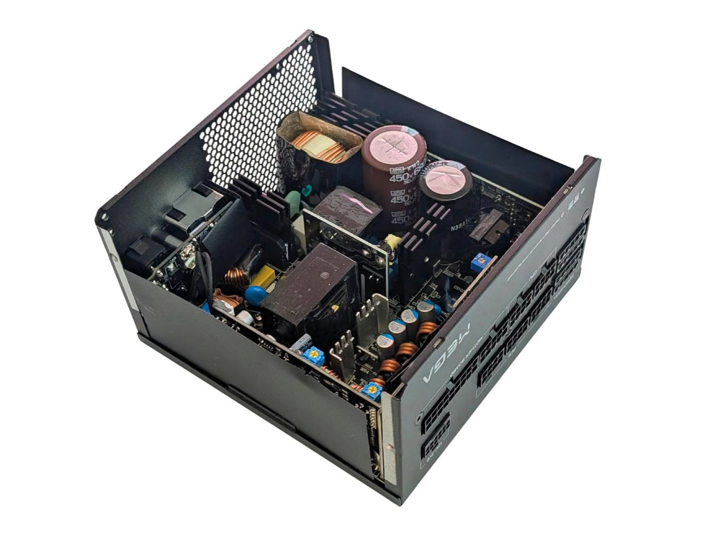
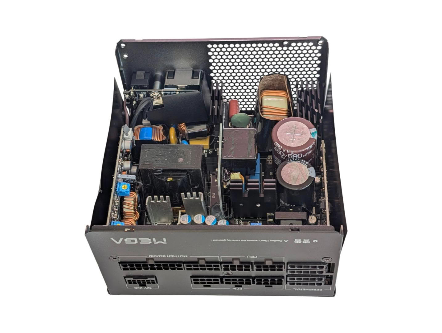
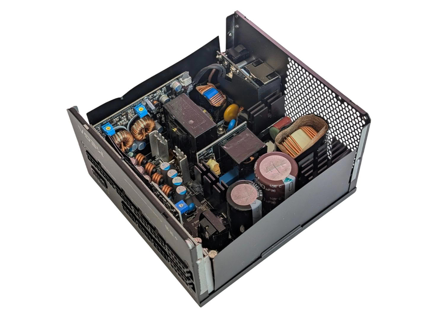
Taking a look inside, this is quite a densely packed unit with plenty of heatsinks, capacitors and daughter boards.
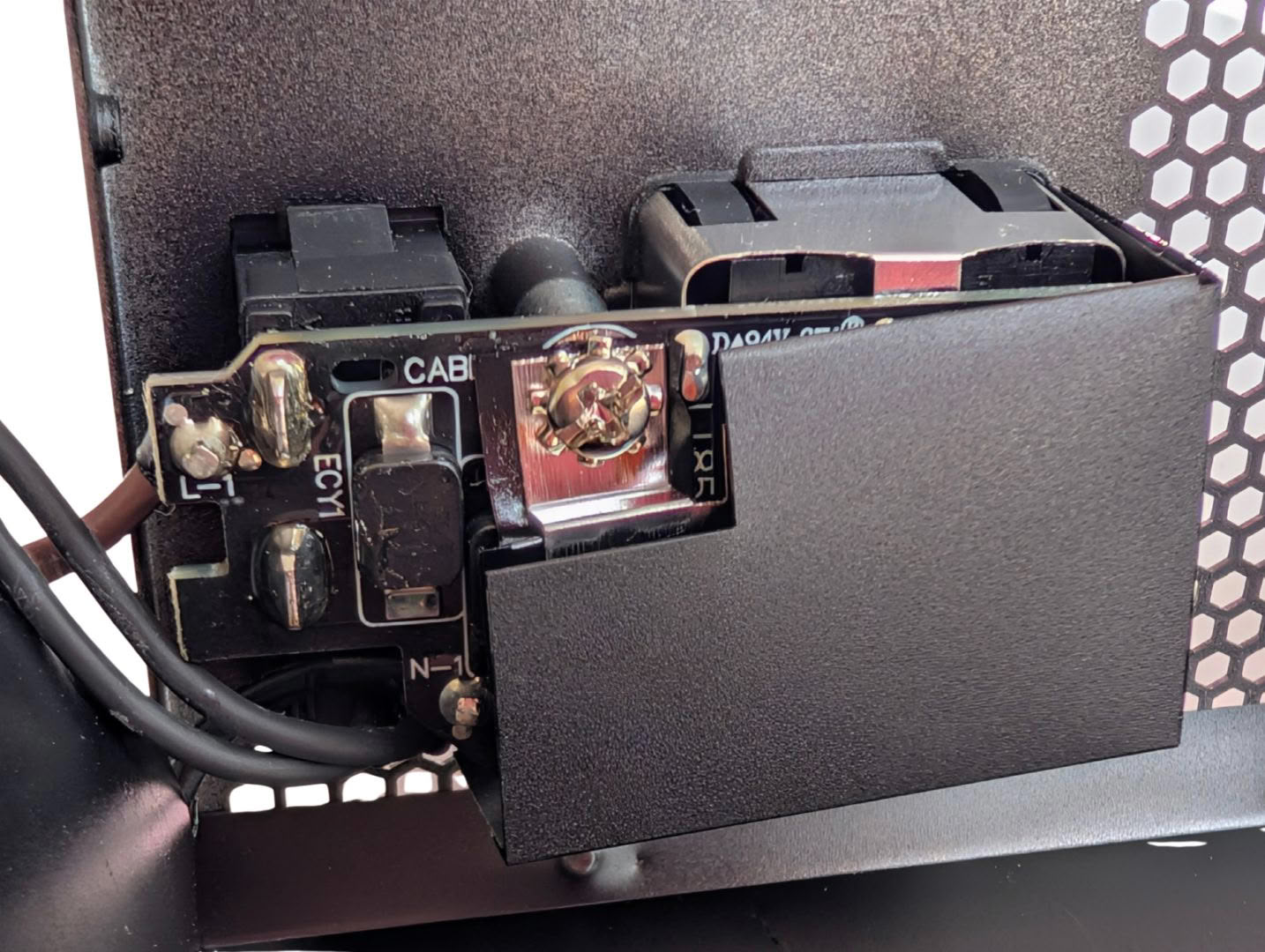
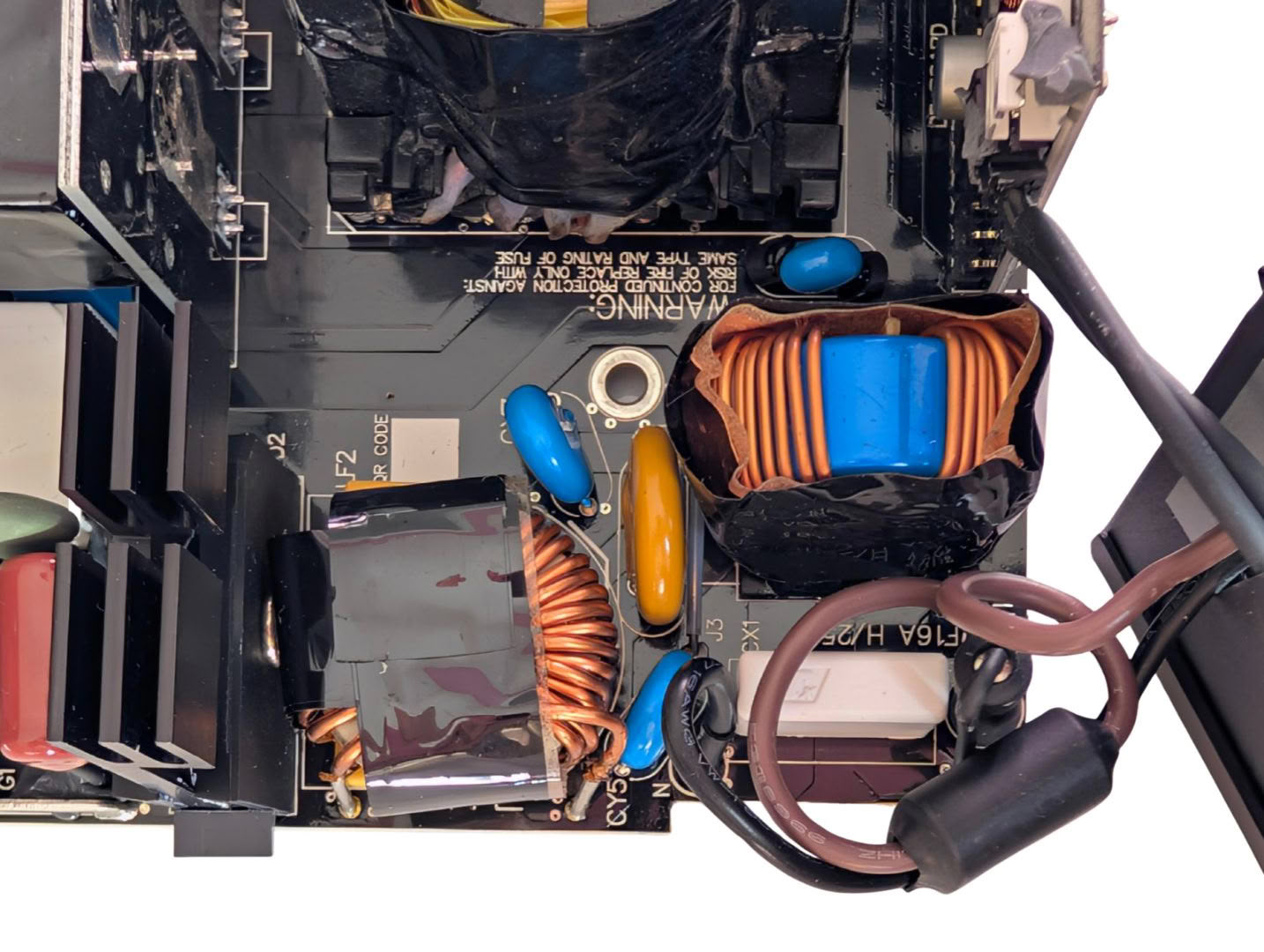
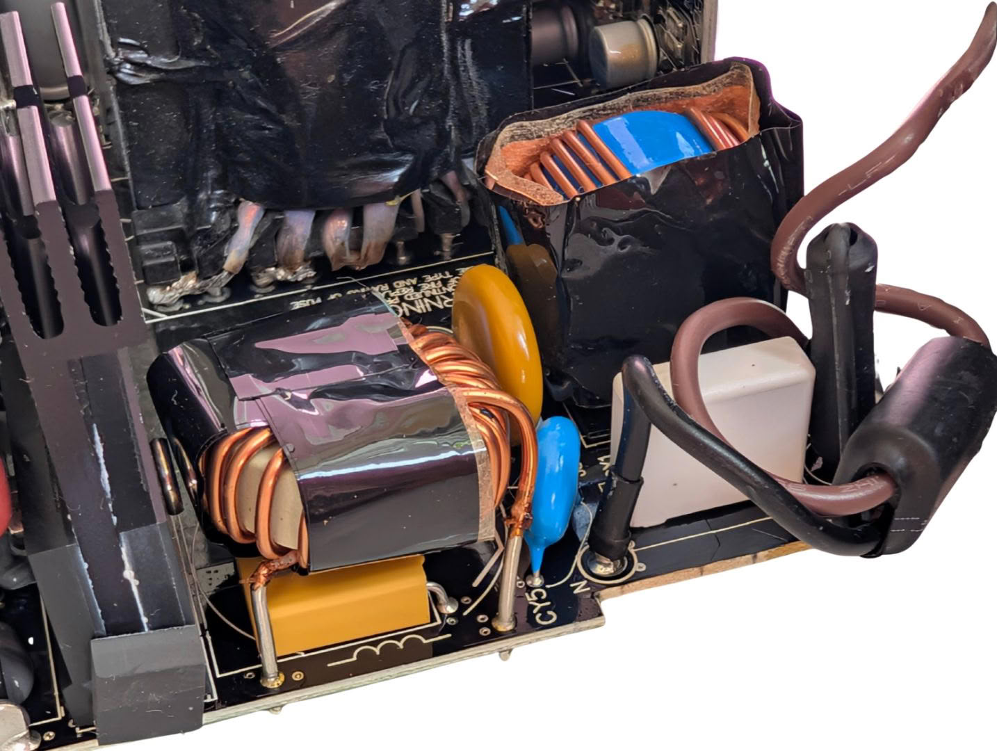
The mains input uses a PCB to house the connector and power switch, along with a visible SMD Y cap and grounded shield over the connector itself. On the main board, there are a pair of X caps and pair of Y caps, two CM chokes, MOV and 16 A fuse.
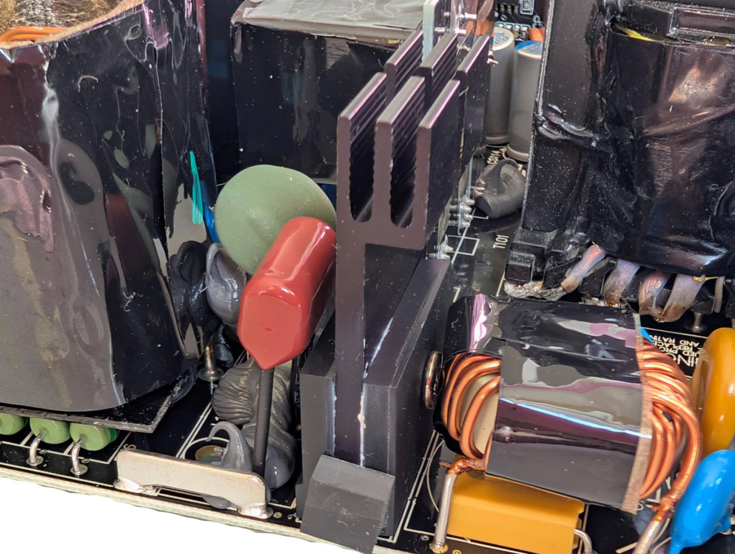
After transient filtering, the AC makes its way to a pair of bridge rectifiers clamped to a small heatsink.
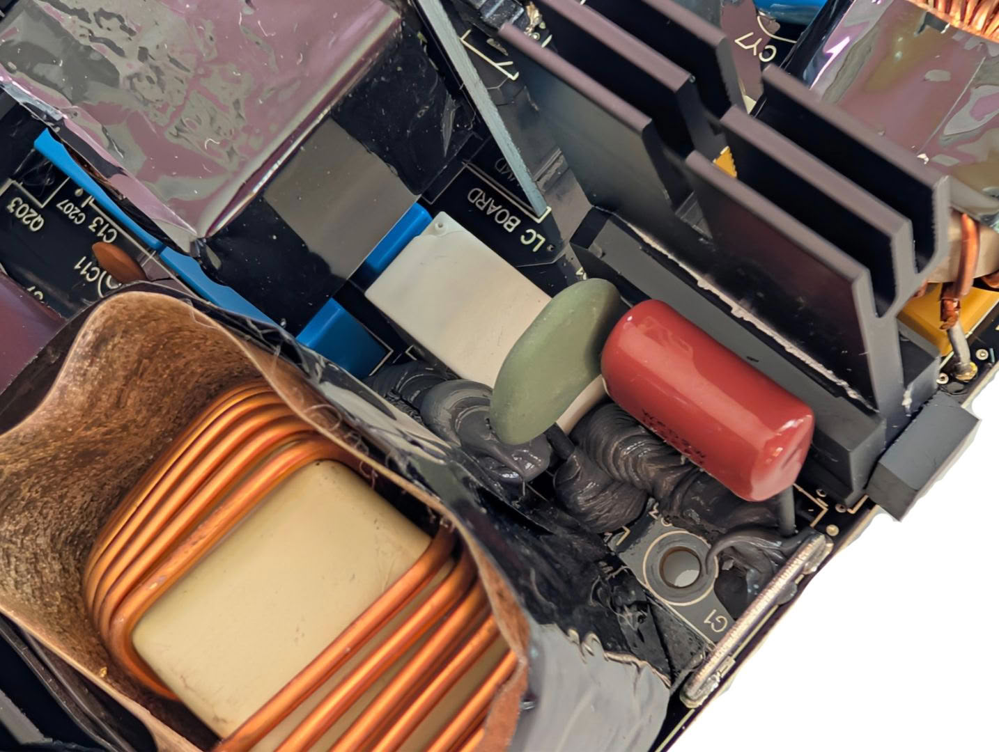
Directly after the rectifiers there is a thermistor and relay to deal with inrush suppression.
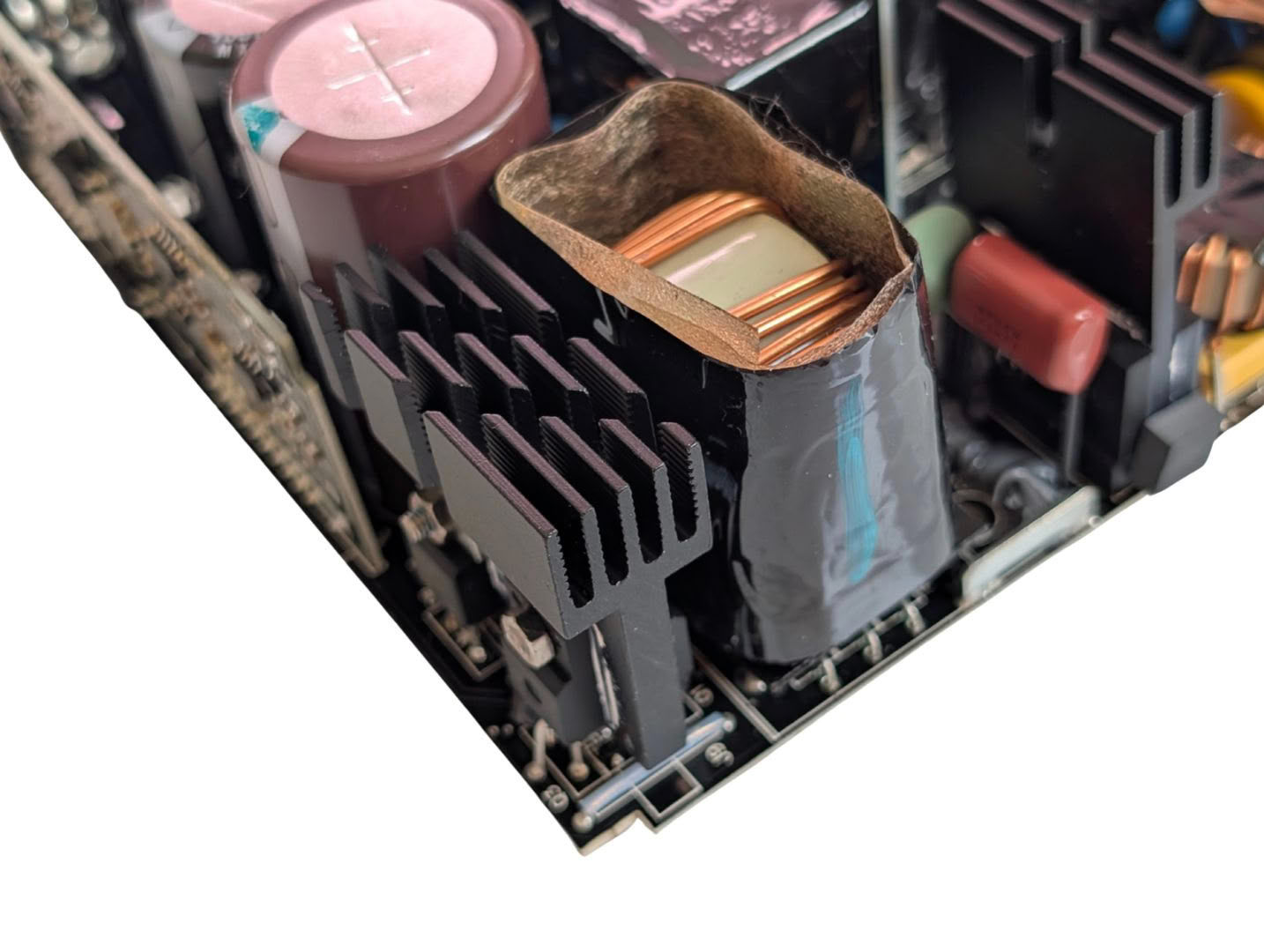
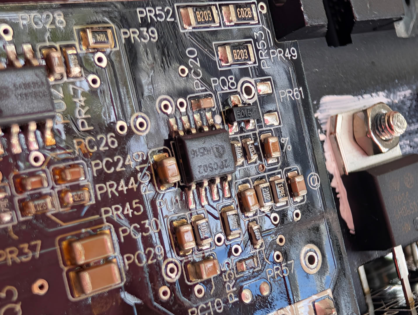
Active PFC is handled by an ICE2PCS02 IC, which drives the gates directly and uses a fixed frequency of 65khz. It operates in Continuous Conduction Mode (CCM) with average current control, and Discontinuous Conduction Mode (DCM) under light loads.
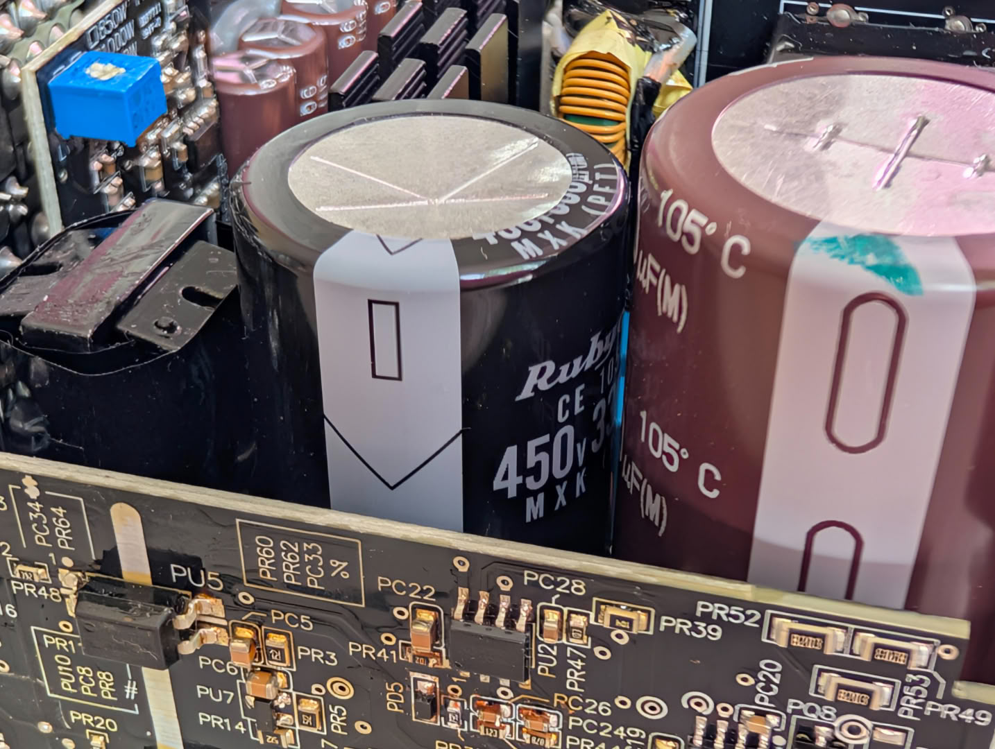
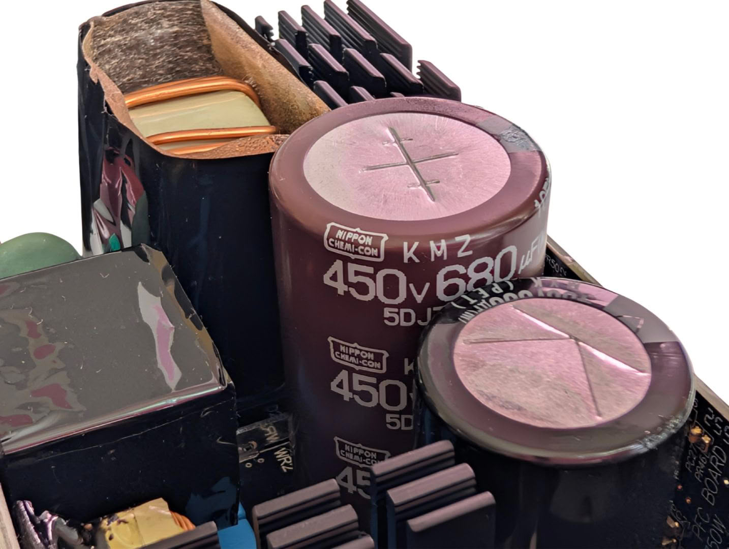
A pair of bulk caps are used, one Nippon Chemi-Con 680uF, and one Rubycon 330uF, for a total bulk capacitance of 1010uF. These are both quality models, rated at 105C.
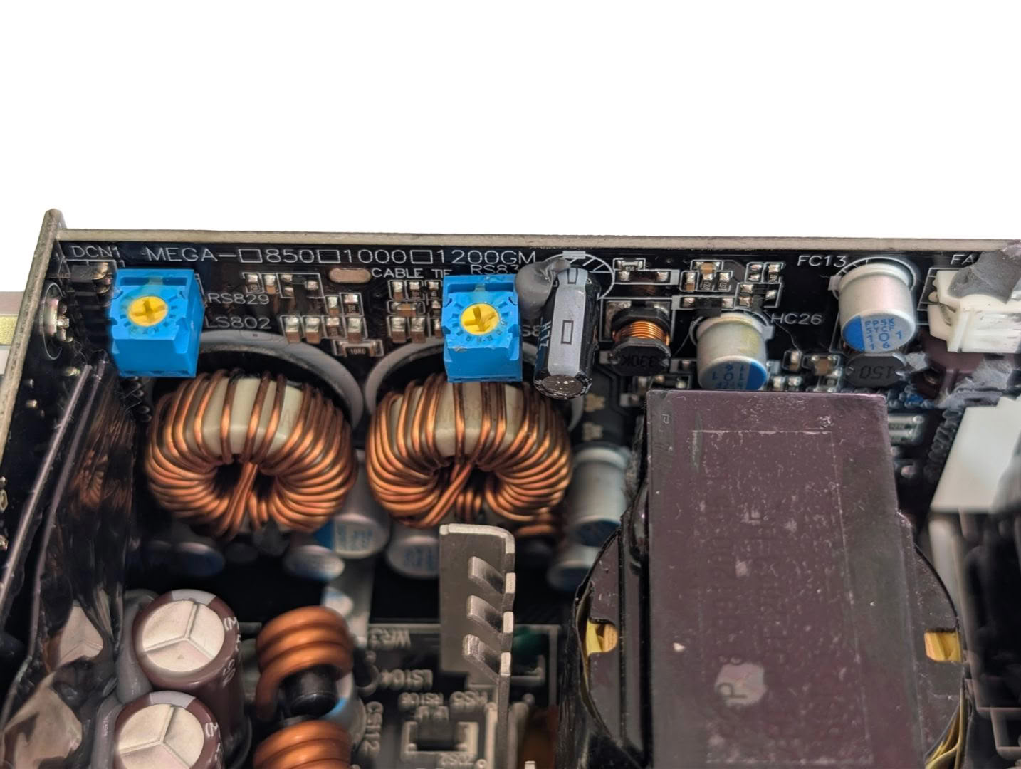
Generating the minor rails is this upright DC-DC board, using two MOSFETs for 3.3 V and 5 V.
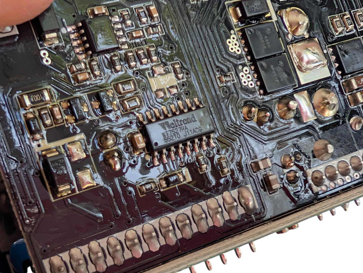
The Weltrend WT7527RA supervisor is also mounted to this board, along with the fan control circuitry.
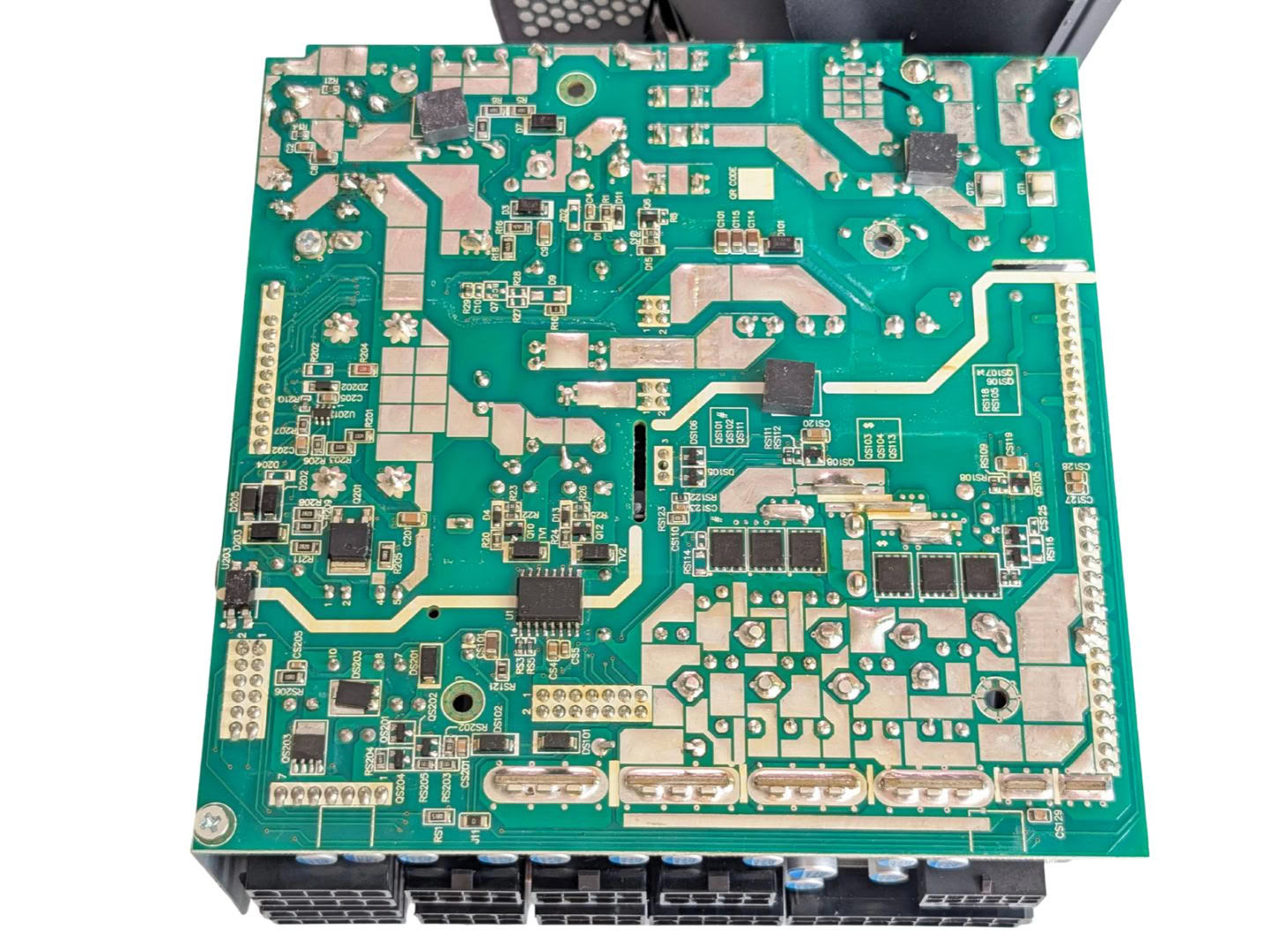
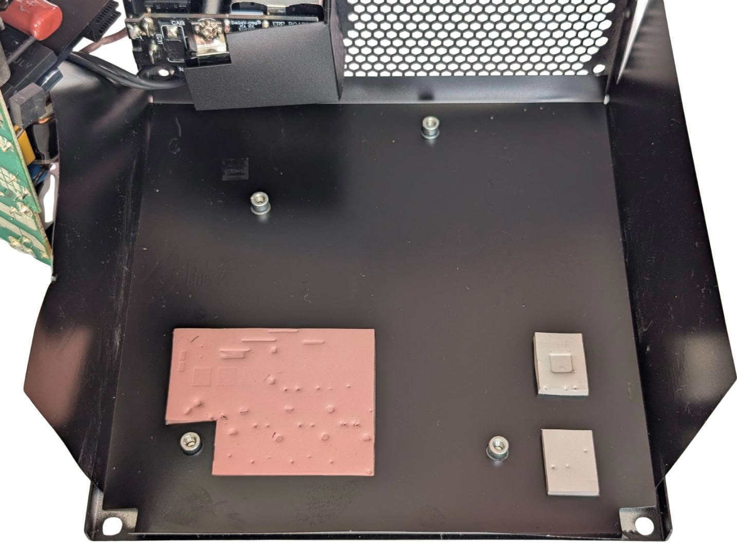
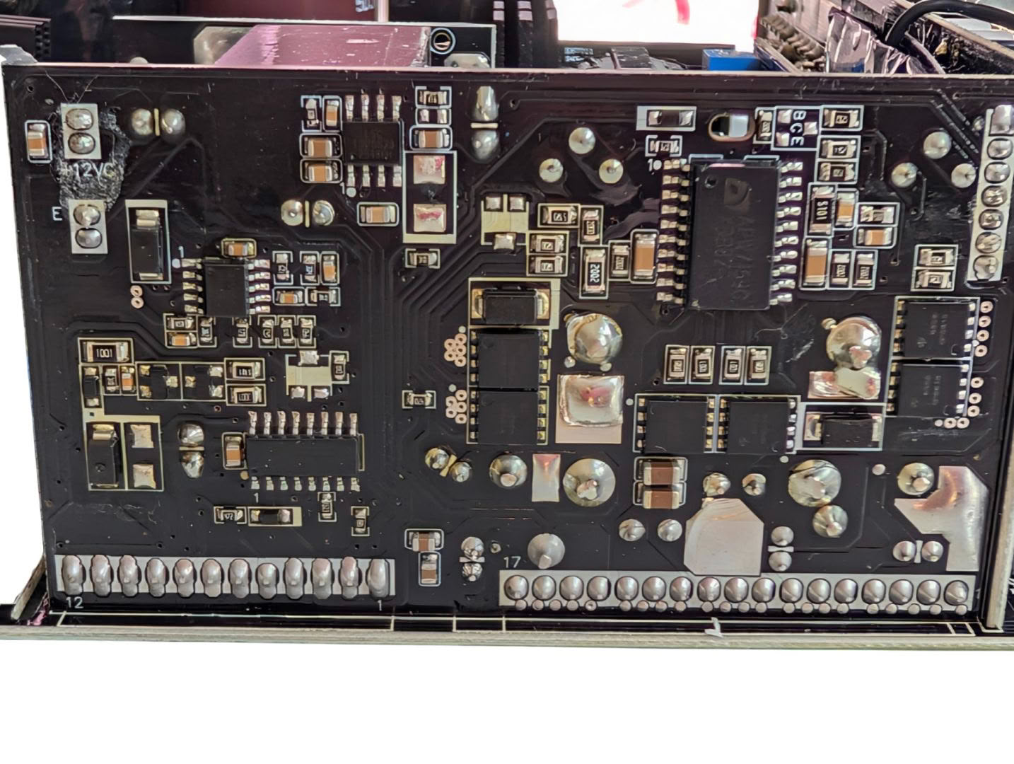
The underside of the board is home to plenty of active components and thick current-carrying traces. There is a heat pad which thermally couples the 12 V drain traces to the case to wick away heat.
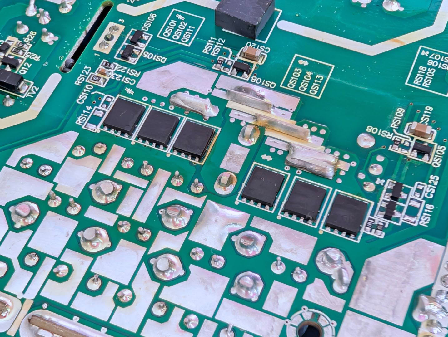
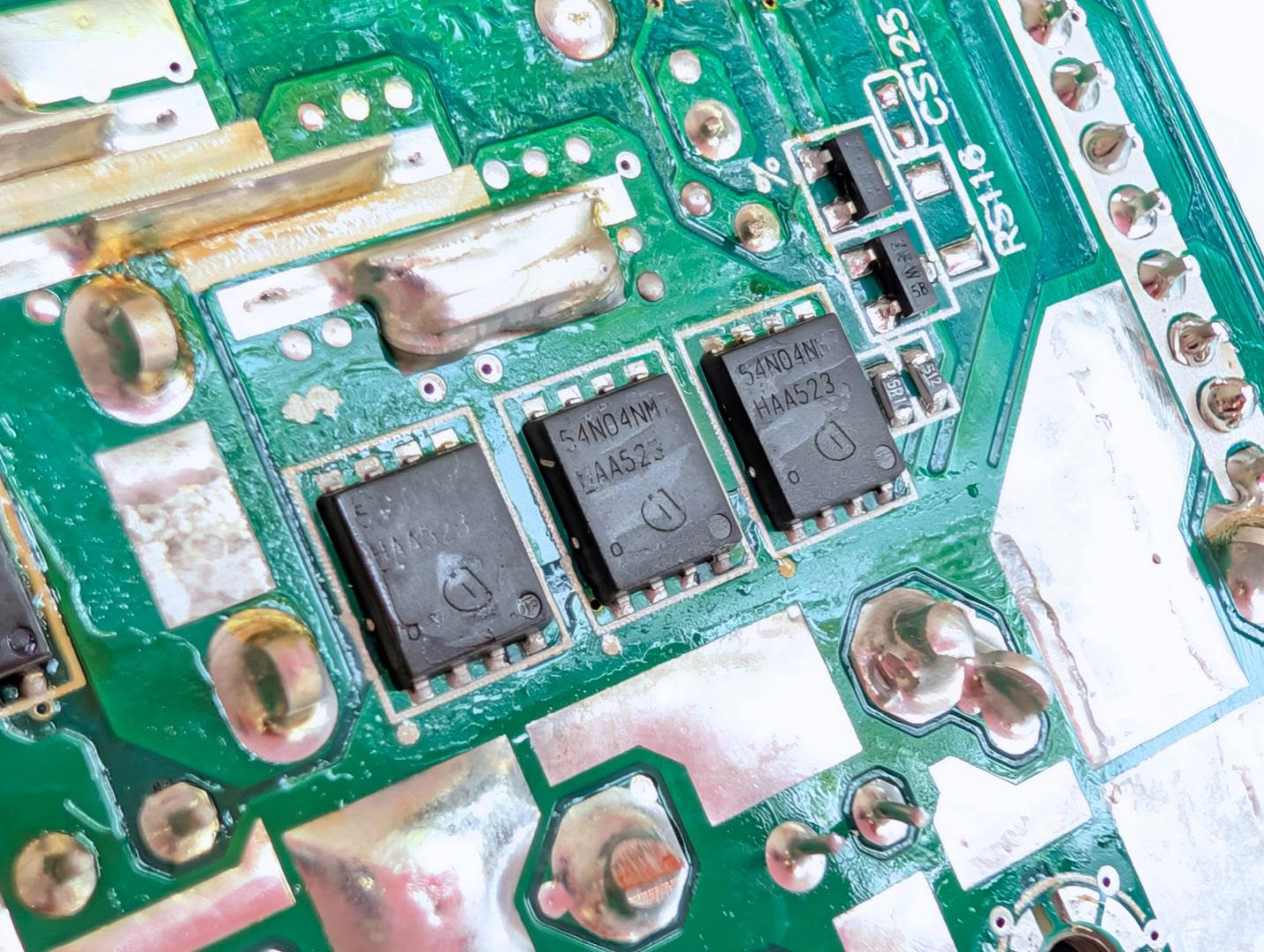
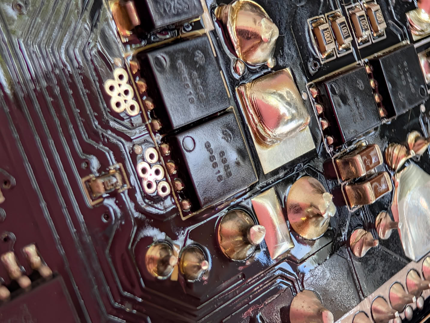
The 12 V rail is generated using six ISCH54N04NM7V MOSFETs, with some wild specifications - 458 A with just 0.58 mΩ RDS(on).
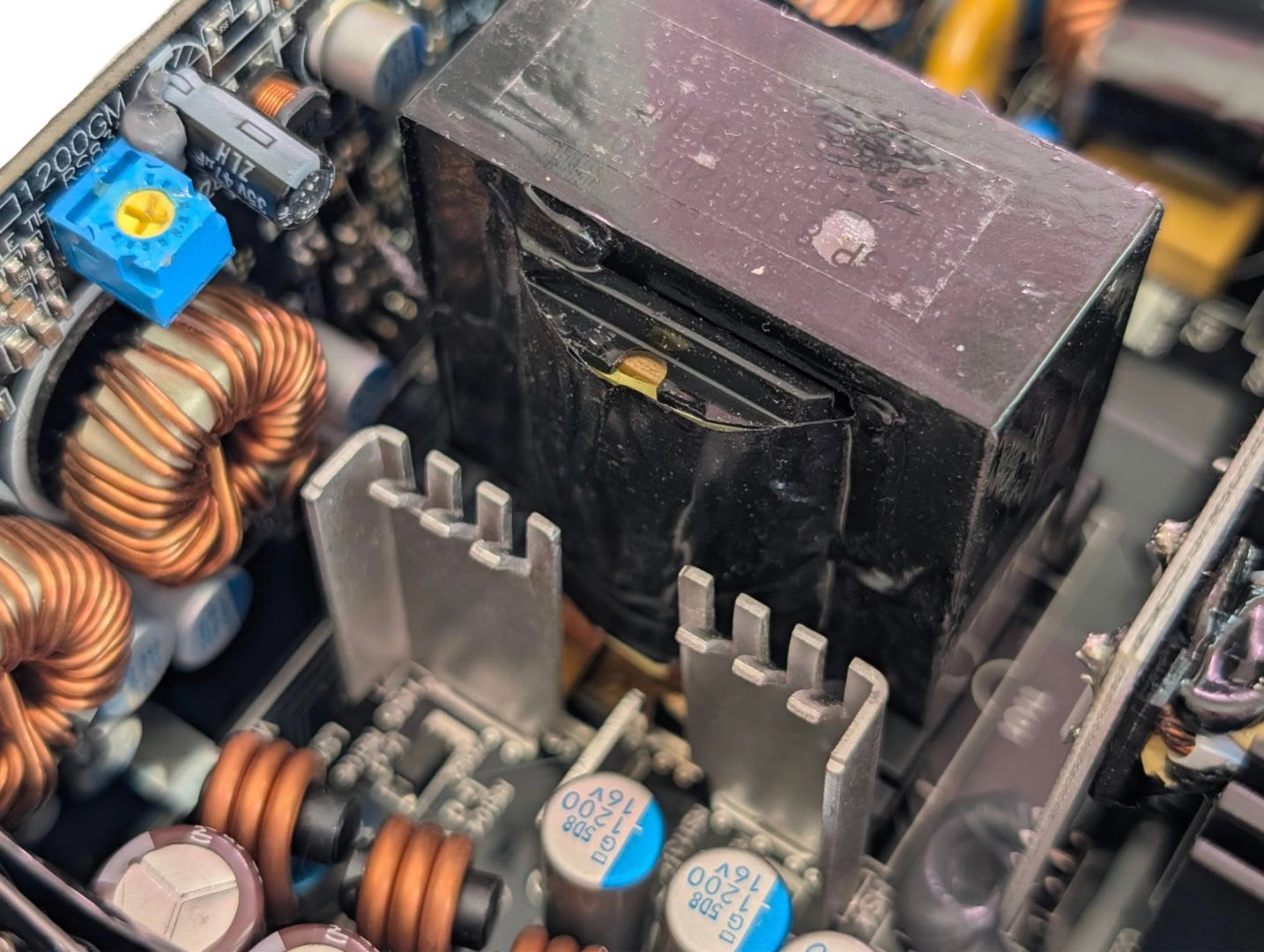
In addition to sinking heat to the case via the underside of the board, there are a pair of heatsinks mounted to the top to pull some heat into the airflow generated by the fan.
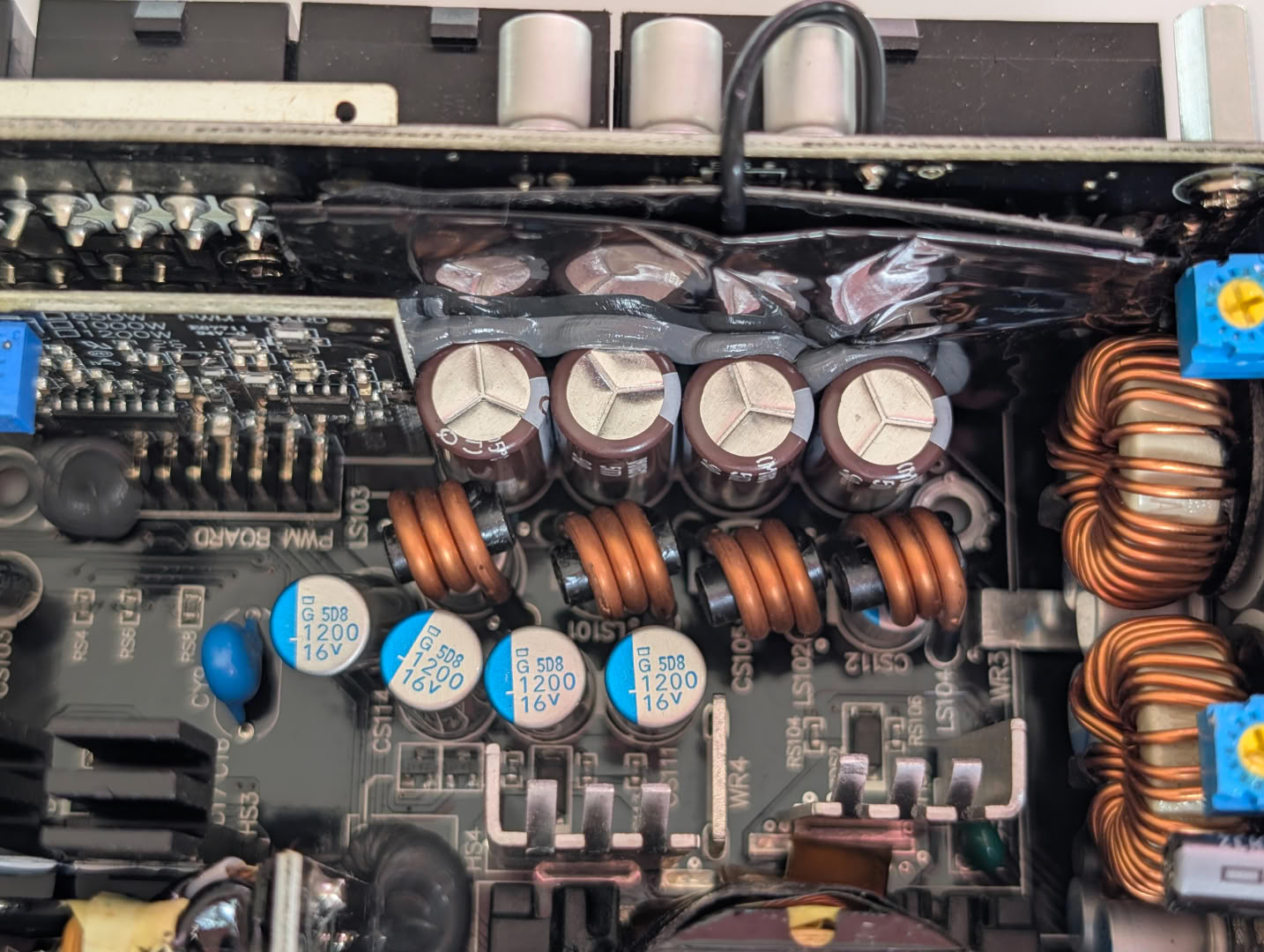
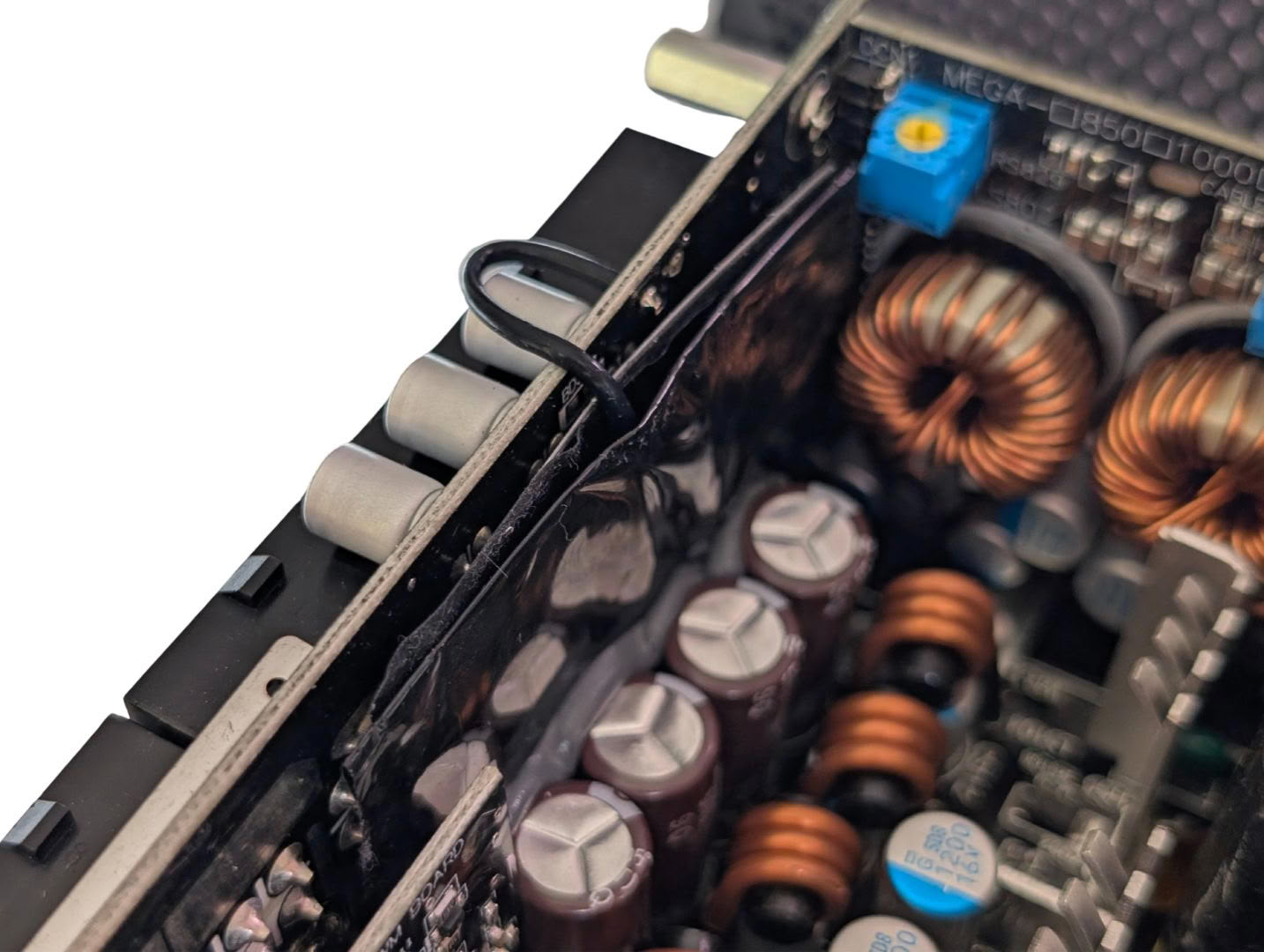
There has been good effort made to reduce ripple and noise on the 12 V rail, by utilising high quality Japanese capacitors, inductors, and a grounded copper sheet between the output connector board and the switching components on the main board.
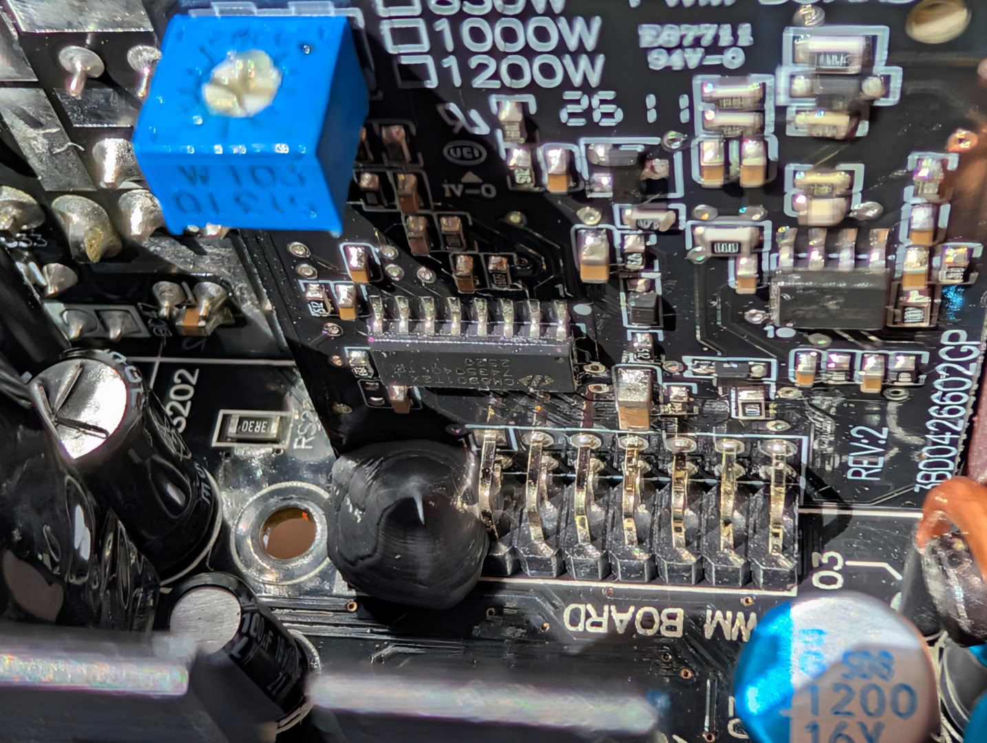
The resonant controller used here is the well-documented CM6901.
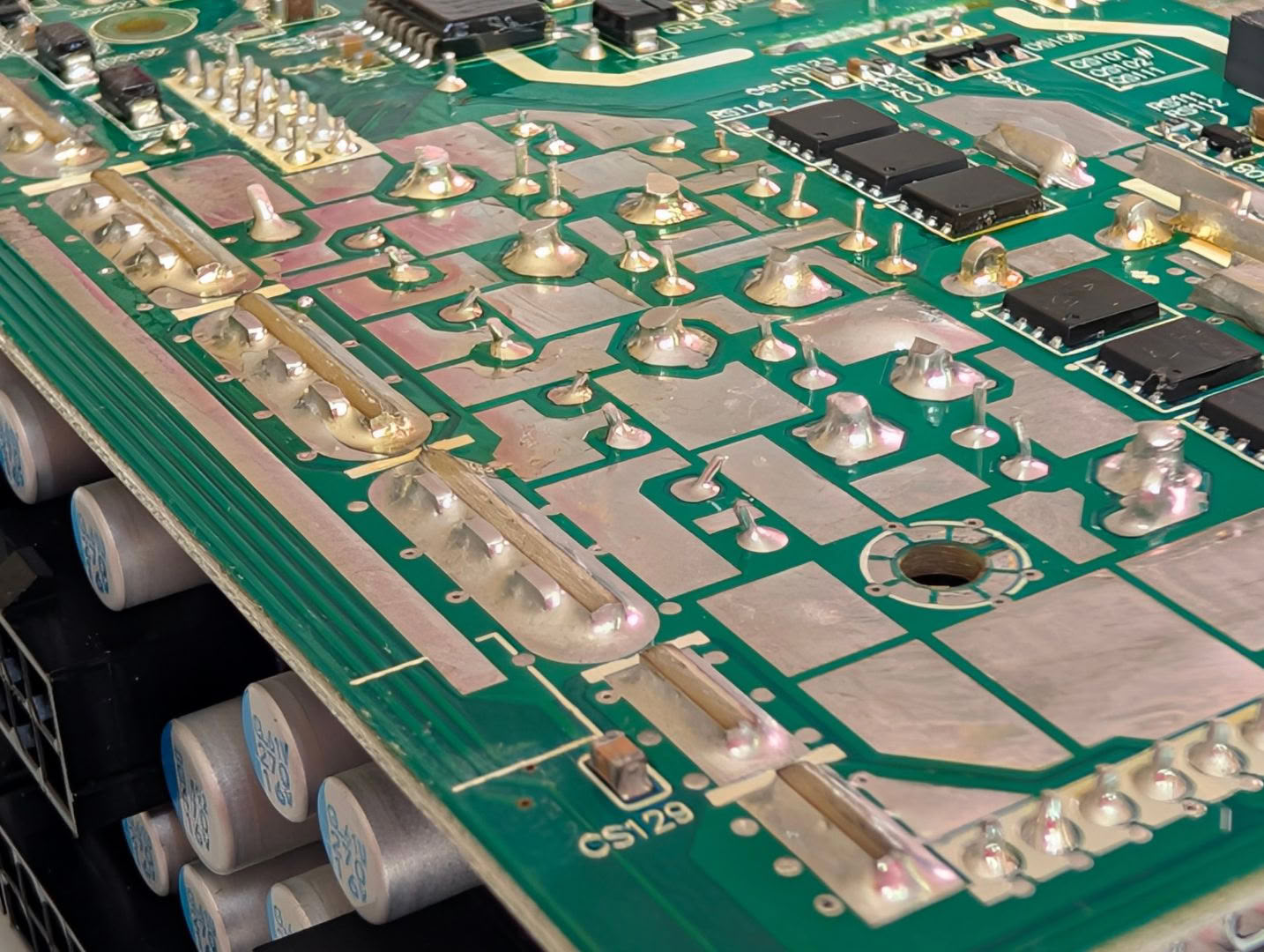
The connection between main and output board is very strong, using thick metal pins in addition to the PCB itself, and the soldering is very consistent.
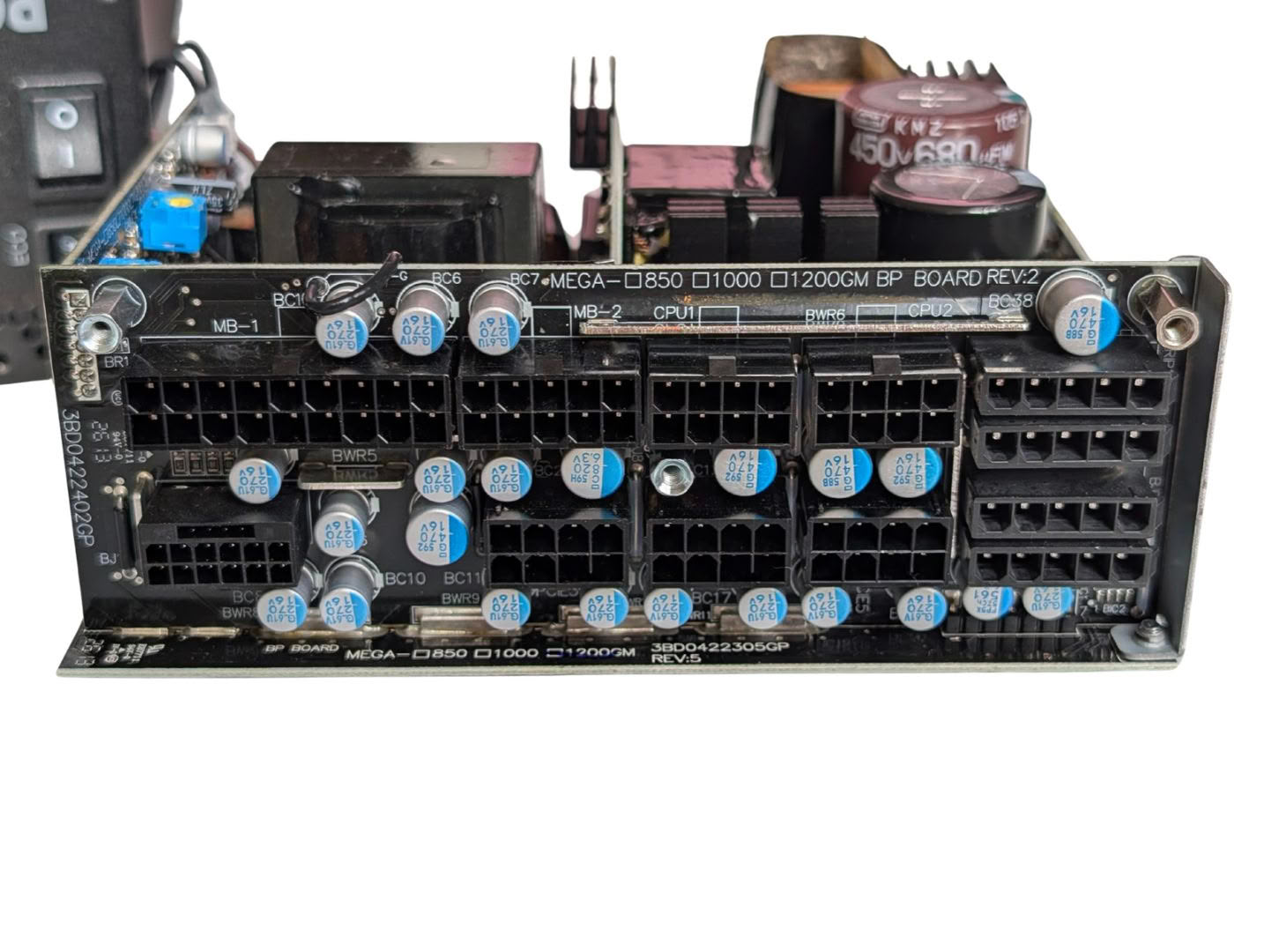
The connector board has plenty of filter caps right alongside each connector, and metal bars to improve current flow to the connectors.
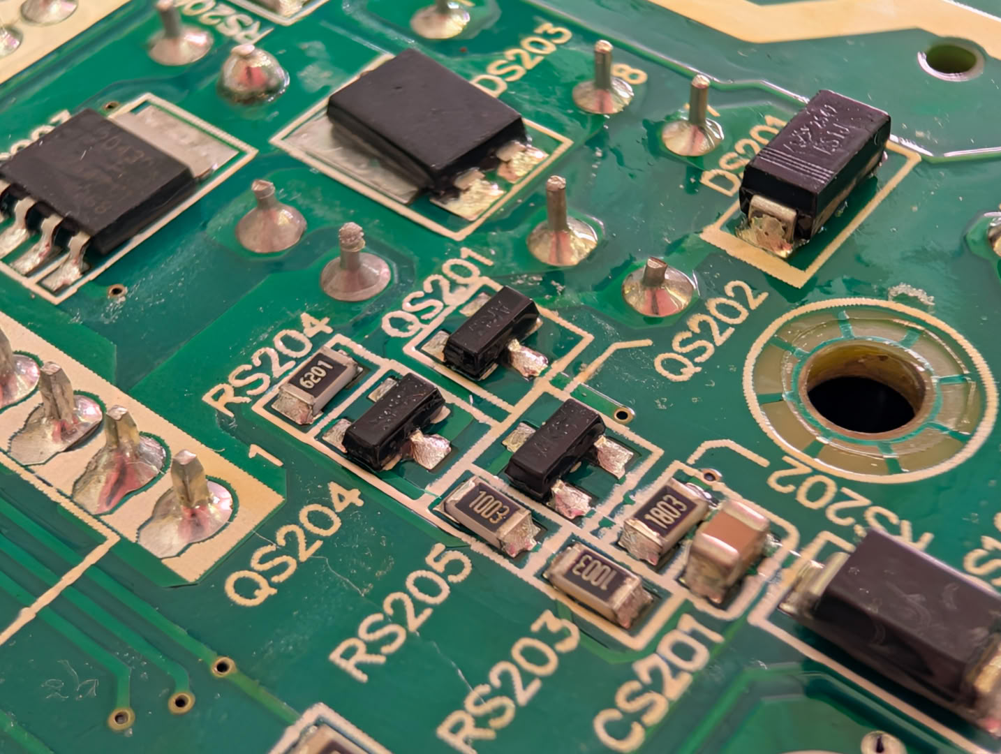
The soldering quality throughout the board is good and consistent, although a few components were noted to be skewed from their ideal position. This isn't an issue, but unless every unit is QC tested at the factory, there may be times where parts were not correctly soldered or touching where they shouldn't.
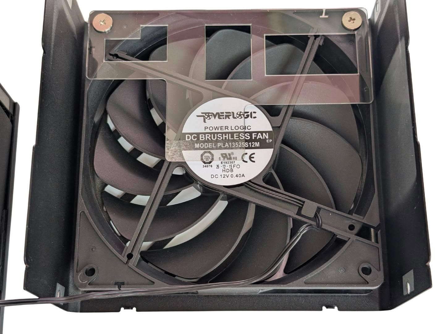
The Power Logic PLA13525S12M 135 mm fluid dynamic bearing fan is often praised for its low noise profile and high reliability, and is a solid choice in this model.
Nov 13th, 2026 21:56 CST
change timezone
Latest GPU Drivers
New Forum Posts
- no "PhysX" workable (8)
- AI generated images... (224)
- Tell me about your favourite graphics card (28)
- Crimson Desert (31)
- RenoDX HDR - how to view the differnce Before&After in game? (0)
- Displayport DP80 3M (10ft) cable that can achieve 80gbps stable? (5)
- I'll flash a ASUS ROG Strix RX480 O8G in Cause of Code 43, as a Newbie (1)
- Opinion on Monitor Replacement (6)
- TMOG - post your benchmark results here (16)
- Microsoft Exchange/365 outages? (61)
Popular Reviews
- AMD Zen 6 Technical Deep Dive
- Corsair HX1000i Shift Crystal Review
- NZXT C1200 Platinum Review
- Upcoming Hardware Launches 2027 (Updated Nov 2026)
- ASUS ROG Strix B850-I Gaming Wi-Fi7 W Review
- Montech King 95 3D PRO Review
- NZXT H7 RGB+ Review
- NZXT H5 Review
- Phantom Blade Zero Performance Benchmark Review - 35 GPUs Tested
- XPG NIMBUS PLUS Review - Mid-range Chair With Strong Competitors
TPU on YouTube
Controversial News Posts
- NVIDIA Co-Founder and CEO Jensen Huang Officially Resigns (379)
- OpenAI CEO Argues Home PCs Waste the World's Limited DRAM Supply (152)
- NVIDIA Launches Investigation Into Jensen Huang's Relationship With Suspected Chinese Spy (136)
- Intel "Raptor Lake Next" 16-Core and 20-Core CPUs Surface (130)
- Legendary Game Studio BioWare Shuts Down Following EA Layoffs (104)
- Dell CEO Says the Memory Shortage Will Get Worse in 2027 (95)
- NVIDIA GeForce RTX 50-Series Scheduled for up to $500 Price Hike This Week (89)
- Modder Fits RTX 5090 With Four 8-Pin Connectors, Halving Current per Wire (80)