 4
4
High Power Astro GD 750 W Review
Voltage Regulation, Hold-up Time & Inrush Current »A Look Inside & Component Analysis
Before reading this page, we strongly suggest a look at this article, which will help you understand the internal components of a PSU much better. Our main tool for the disassembly of the PSU is a Thermaltronics TMT-9000S soldering and rework station. It is of extreme quality and is equipped with a matching de-soldering gun. With such equipment in hand, breaking apart every PSU is like a walk in the park!


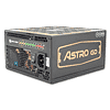
High Power decided to enter the digital era in PSU manufacturing with the AGD-750 as their first venture into this area. That said, we discovered the digital control portion to be restricted to the DC-DC modules generating the minor rails. Nor do we know how much is involved as a standard PWM controller is also present. The platform is modern because an LLC resonant converter is used in the primary side to boost efficiency and since the secondary's synchronous design along with the aforementioned DC-DC modules handle the generation of the main rails.
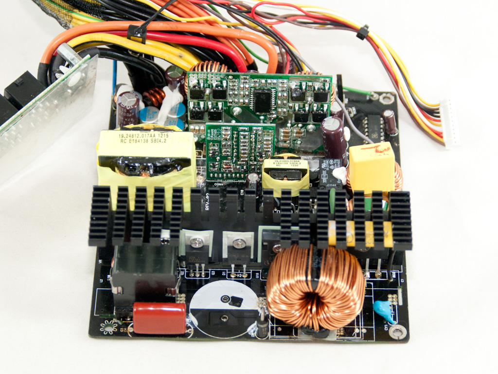
The transient filtering stage starts at the AC receptacle with one X cap and a pair of Y caps. A CM02X is mounted on the X cap, and its job is to block current through the cap discharge resistor when AC voltage is connected. It also automatically discharges the aforementioned cap through the discharge resistor when AC is disconnected. This procedure leads to higher efficiency since X caps tend to keep their charge for quite a long time once AC power is cut off, which is why bleeding resistors have to be used as a safety precaution. However, some energy is lost on such resistors while the PSU is operating, something that the CM02X takes care of by cutting the bleeding resistor off the circuit. The second part of the transient filter is located on the main PCB and consists of two CM chokes, a single X cap, and two Y ones. An MOV is also present, and we located an NTC thermistor responsible for high inrush current protection and a relay that isolates it from the circuit once the start-up phase finishes nearby.


The two parallel bridges (GBU805) are bolted to the primary heatsink. They can handle up to 16 A of current combined, which should suffice for this PSU.


In the APFC circuit, a single fet, an Infineon IPW60R125CP, chops the full wave rectified signal coming from the bridge rectifiers into constant pulse sequences. A CREE C3D08060A boost diode also helps in boosting voltage to around 380 VDC. The bulk cap is provided by Panasonic (400 V, 680 μF, 105°C) and has enough capacity to cover the needs of a 750 W PSU.

The PFC controller is installed on the main PCB. It is a Champion CM6502 that is, according to its manufacturer, designed to meet the 90+ spec .

Two ICE60N150 fets are used as main switchers.


The LLC resonant controller is a Champion CM6901. It is installed on this vertical daughter-board. So far, neither the APFC and the primary side are digitally controlled, like in the Corsair AXi units. The digital control is apparently restricted to the DC-DC modules, but we will talk about that in the following paragraph.


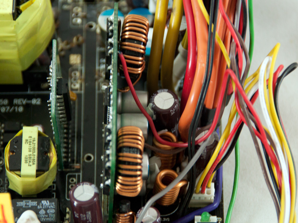
We had to de-solder the secondary heatsink to clear things out and have a better look at the DC-DC modules. This wasn't an easy task since the sample we had in our hands was most likely an early production one, so soldering quality was bad, with messy, huge solder joints and a main PCB that wasn't of the best shape. We found eight fets in total and a single PWM controller, an APW7159, on the vertical PCB that holds both VRMs generating the minor rails. We also noticed two cables going from the digital circuit to the VRMs. What sort of an interaction takes place between the digital circuit and the VRMs then is impossible to figure out since a PWM controller is already present. Only High Power's engineers can shed some light on this matter.
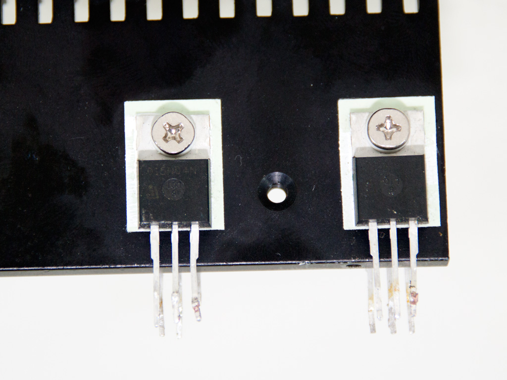


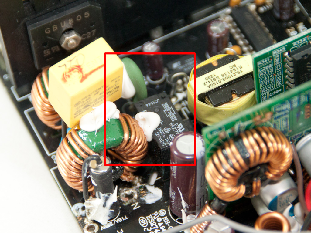
The secondary heatsink has four 015N04N fets generating +12V and a single PFR30L45CT SBR that rectifies 5VSB. There are also several polymer filtering capacitors on the secondary side, with a few electrolytic ones. All are provided by Nippon Chemi-Con.

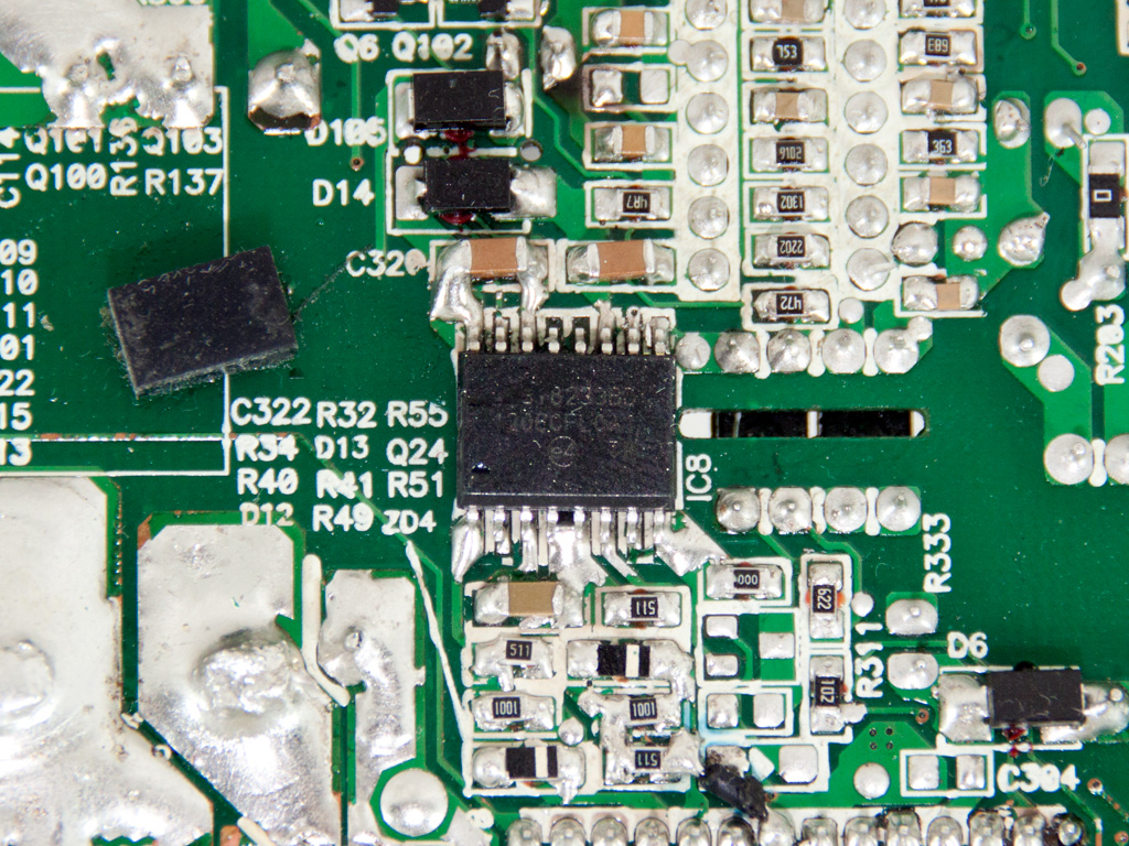
The protections IC is a SITI PS223. It is installed on the main PCB.

The standby PWM controller is a Power Integrations TNY278PN IC.

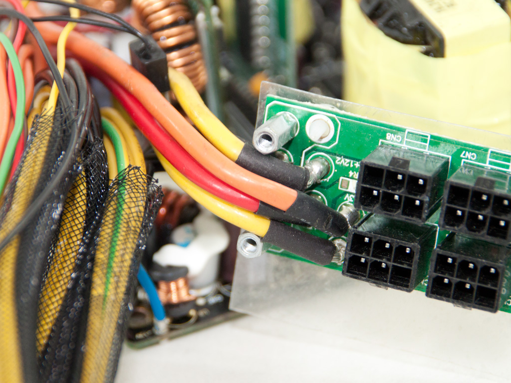

Some really thick cables transfer power to the modular board. A plastic shield on its back provides protection against shorts.
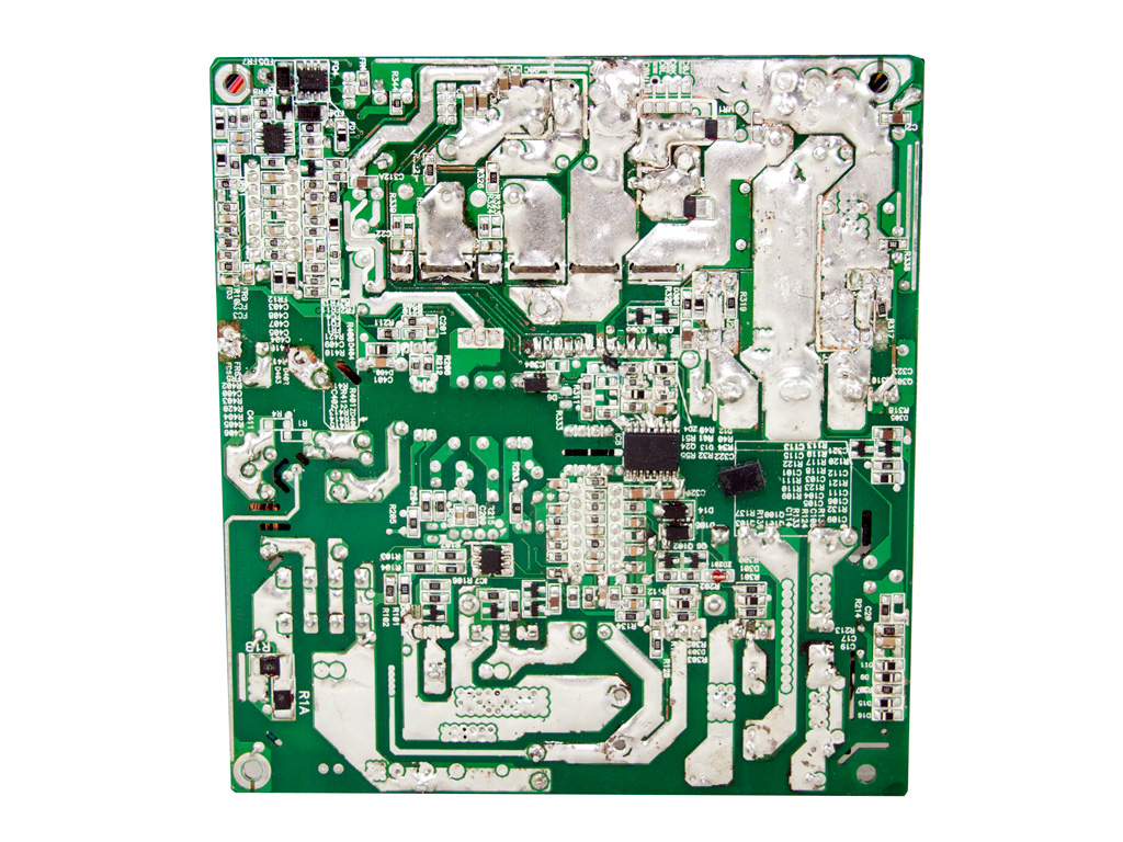


The solder side of the main PCB isn't exactly pleasant to look at since soldering quality was bad, with excess amounts of solder having been used all over the place. This is due to the fact that the sample we have on our hands is a pre-production model. High Power PSUs, especially high-end ones, are normally of good soldering quality, so we expect their normal production models to also be of good soldering quality.
We spotted this IC on the solder side. It is Silicon Labs Si8233BD isolator interface, and its task is to isolate the primary side from the secondary one.


This board houses the LED indicators of the power meter. It is controlled by an 8-bit micro-controller (EM78M611E) that is provided by Elan Microelectronics Corporation. The same controller is also used in the Thunderbolt Plus 1200 W unit, where it controls the iPower device this PSU is equipped with. The EM78M611E controller has both a PWM function and an AD (Analog to Digital) converter built-in, but whether the DC-DC modules of this unit exploit the PWM function remains unclear.

The cooling fan is provided by Globe Fan, and its model number is RL4Z B1352512M (12 V, 0.28 A). It uses double ball-bearings for increased longevity and is a low RPM fan, so we don't expect it to be noisy but silent.
Apr 25th, 2024 16:58 EDT
change timezone
Latest GPU Drivers
New Forum Posts
- im new to throttelstop and i think i messed it up by copying others any hints would be very much aprreciated (2)
- Ryzen Owners Zen Garden (7243)
- What software are you using to monitor CPU temps during gaming session? (15)
- ROG Strix LC III 360 ARG AIO What should the pump speed be? (4)
- Ghetto Mods (4322)
- Legion Pro 7i, i9-13900HX. PL2 limit reason in log file (0)
- Alphacool CORE 1 CPU block - bulging with danger of splitting? (15)
- What are you playing? (20528)
- What phone you use as your daily driver? And, a discussion of them. (1480)
- Black screen after muting (4)
Popular Reviews
- Fractal Design Terra Review
- Thermalright Phantom Spirit 120 EVO Review
- Corsair 2000D Airflow Review
- Minisforum EliteMini UM780 XTX (AMD Ryzen 7 7840HS) Review
- ASUS GeForce RTX 4090 STRIX OC Review
- NVIDIA GeForce RTX 4090 Founders Edition Review - Impressive Performance
- ASUS GeForce RTX 4090 Matrix Platinum Review - The RTX 4090 Ti
- MSI GeForce RTX 4090 Suprim X Review
- MSI GeForce RTX 4090 Gaming X Trio Review
- Gigabyte GeForce RTX 4090 Gaming OC Review
Controversial News Posts
- Sony PlayStation 5 Pro Specifications Confirmed, Console Arrives Before Holidays (116)
- NVIDIA Points Intel Raptor Lake CPU Users to Get Help from Intel Amid System Instability Issues (106)
- Windows 11 Now Officially Adware as Microsoft Embeds Ads in the Start Menu (105)
- AMD "Strix Halo" Zen 5 Mobile Processor Pictured: Chiplet-based, Uses 256-bit LPDDR5X (101)
- US Government Wants Nuclear Plants to Offload AI Data Center Expansion (98)
- AMD's RDNA 4 GPUs Could Stick with 18 Gbps GDDR6 Memory (86)
- Developers of Outpost Infinity Siege Recommend Underclocking i9-13900K and i9-14900K for Stability on Machines with RTX 4090 (85)
- Windows 10 Security Updates to Cost $61 After 2025, $427 by 2028 (84)