 1
1
LEPA G700-MA 700 W Review
Voltage Regulation & Efficiency »A Look Inside
Before reading this page we strongly suggest to take a look at this article, which will help you understand the internal components of a PSU much better.


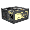
The internals of the G700-MA are exactly the same as the Enermax MODU87+ 700W (EMG700AWT). The only visual difference we spotted was that instead of blue anodized color the heatsinks in this unit are painted in black. This platform utilizes an LLC converter to achieve zero voltage switching on the primary FETs and thus decrease energy losses and boost efficiency to gold levels.
The first part of the transient filtering stage is housed on a small PCB right behind the AC receptacle. There four Y, one X and a CM choke. On the main PCB we find more transient filtering components, namely two coils and an MOV.


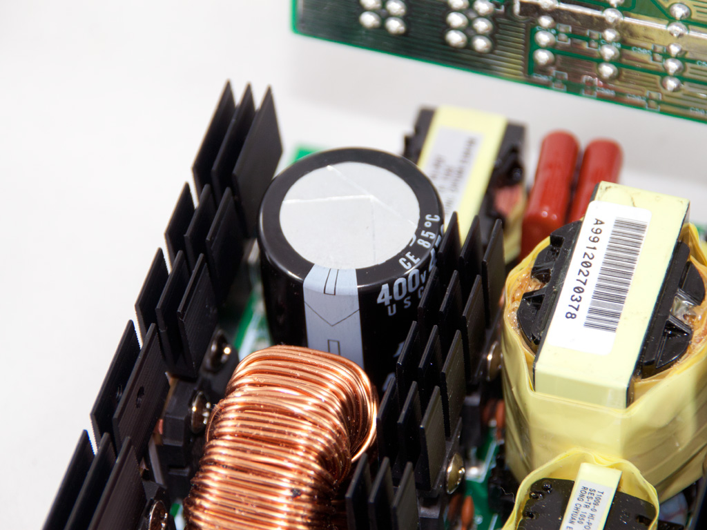
The bridge rectifier is bolted on a dedicated heatsink and right in front of it we find the PFC input capacitor which filters the high frequency ripple of the fully rectified AC signal. The two large resistors are used for current sense purposes from the PFC controller. Speaking of which, it's a CM6502 IC and resides on the solder side of the main PCB.
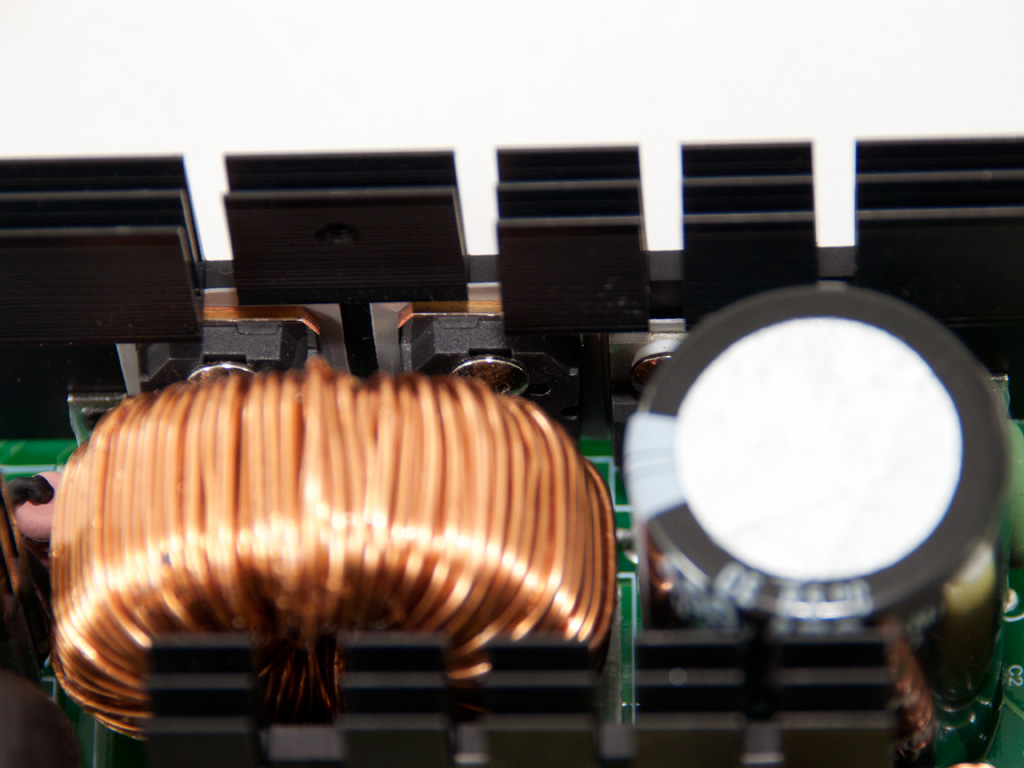

In the APFC two TK20J60T FETs along with a boost diode help the shaping process of current waveform in order to match the corresponding of the voltage. The hold up cap is provided by Rubycon and is rated only at 85°C. It has relatively small capacitance (470μF) for the power of the unit and it's rated at 400V, very close to the 380VDC bus of the APFC.

As primary switches two SiHG20N50C are used. The LLC resonant controller is soldered on the back side of the main PCB and is provided by Champion (CM6901).


In the secondary side synchronous design is used so the regulation of the +12V rails is handled by four IRFB3206 fets. Afterwards, through two DC-DC buck converters the minor rails are generated from +12V. On each VRM there is an APW7073 PWM controller and three APM2556 FETs.


All filtering capacitors in the secondary, both polymer and electrolytic ones, are provided by Nippon Chemi-Con.


The protections IC, a PS231S, is soldered on a small PCB in the secondary side. Among others it supports OCP for three +12V rails, matching the unit's characteristics.


Unfortunately the modular PCB doesn't use a double sided PCB for increased conductivity and lower resistance. On the solder side there is a lonely polymer cap which filters 5V.


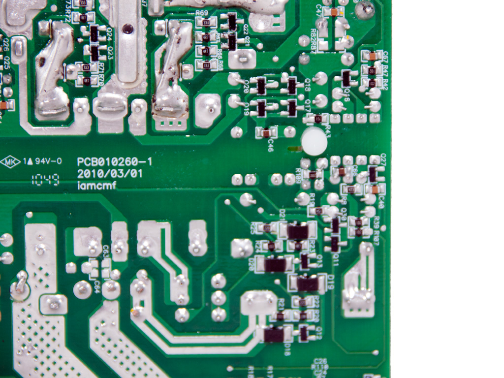
Soldering quality on the main PCB is good overall although in some places we found sloppy, hand made, solder joints. Nevertheless compared to previous Enermax Modu87+ units we have seen in the past this one features way improved workmanship although still far behind Delta and Seasonic levels. Under the +12V islands there are three shunt resistors, matching the +12V virtual rails.

The shiny gold fan is provided by Enermax and its model number is EA142512W-OAB (12V, 0.15A). It uses twisted-bearing.
Jun 1st, 2024 19:58 EDT
change timezone
Latest GPU Drivers
New Forum Posts
- How to reduce Asus mining rx470 4096 mb to 2048 mb vram? (6)
- How do you get games for PC? (12)
- Last game you purchased? (312)
- SSD cooling advice (4)
- V Rising Lycanthropy Club (9)
- Your PC ATM (34594)
- Core counting (67)
- Dude, youre hotrodding a Dell... (0)
- Would you pay more for hardware with AI capabilities? (87)
- 3D/Game Design Workstation (7)
Popular Reviews
- ID-Cooling FX360 PRO Review - Shots Fired @ Arctic
- SilverStone KL07E Review
- NuPhy Air96 V2 Low Profile Wireless Mechanical Keyboard Review
- Senua’s Saga: Hellblade II: DLSS vs. FSR vs. XeSS Comparison Review
- Upcoming Hardware Launches 2024 (Updated May 2024)
- Montech Titan Gold 1000 W Review
- Elysian Acoustic Labs Pilgrim In-Ear Monitors Review
- Waizowl OGM Cloud Review
- Ghost of Tsushima Performance Benchmark Review - 35 GPUs Tested
- Senua's Saga: Hellblade II Performance Benchmark Review
Controversial News Posts
- AMD to Redesign Ray Tracing Hardware on RDNA 4 (227)
- NVIDIA to Only Launch the Flagship GeForce RTX 5090 in 2024, Rest of the Series in 2025 (154)
- AMD Hits Highest-Ever x86 CPU Market Share in Q1 2024 Across Desktop and Server (140)
- AMD RDNA 5 a "Clean Sheet" Graphics Architecture, RDNA 4 Merely Corrects a Bug Over RDNA 3 (139)
- NVIDIA RTX 5090 "Blackwell" Founders Edition to Implement the "RTX 4090 Ti" Cinderblock Design (118)
- Core Configurations of Intel Core Ultra 200 "Arrow Lake-S" Desktop Processors Surface (101)
- Biden Administration to Revive Trump-Era Tariffs on China-made GPUs and Motherboards (95)
- AMD Ryzen 9000 Zen 5 Single Thread Performance at 5.80 GHz Found 19% Over Zen 4 (87)