 12
Memblaze PBlaze7 7A46 6.4 TB Review - Random Write King
NVMe Power States »Teardown
Upon opening the SSD, we see that it's secured with four Torx T-6 screws. Once removed, the back side of the PCB is revealed, firmly attached to the metal housing via several thermal pads that help dissipate heat from key components.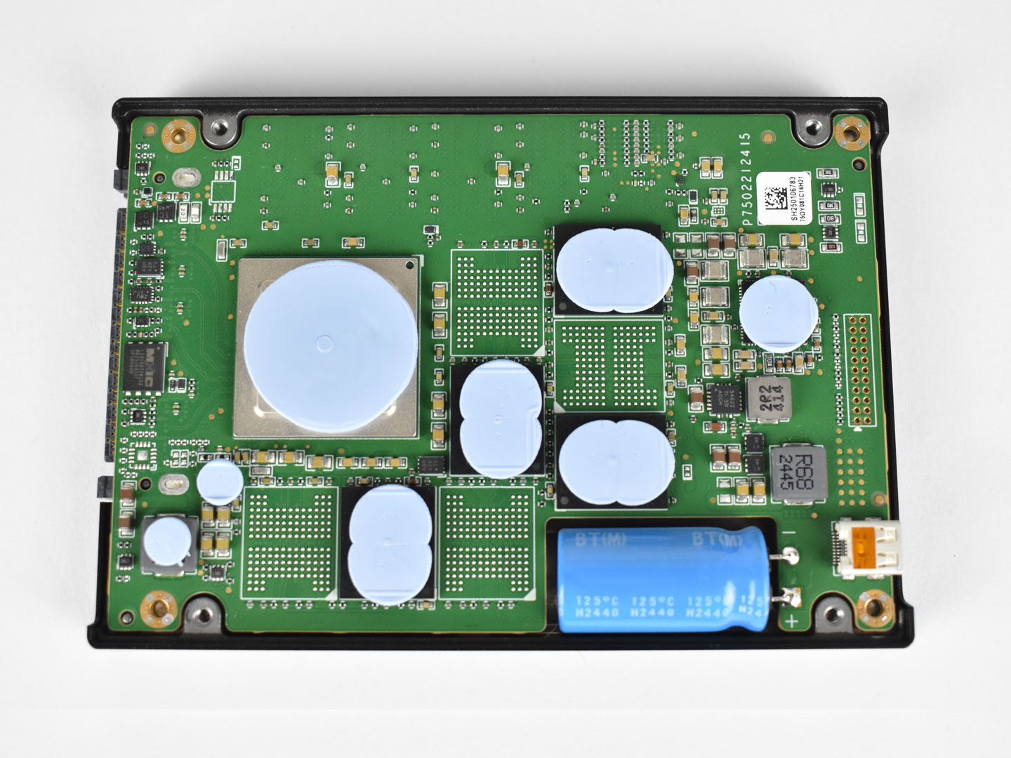
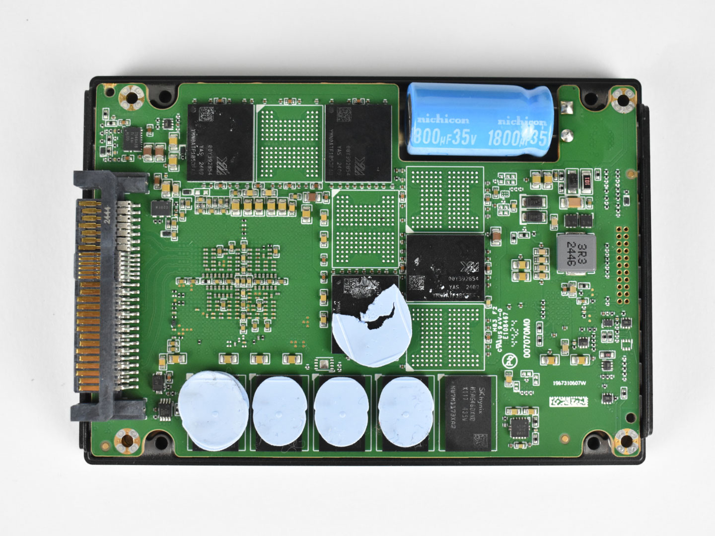
After removing all four screws, we can detach the PCB from its metal enclosure, revealing both the front and rear PCBs. On the front side, we find four NAND flash packages along with the controller and several VRM components. On the rear side, there are four additional NAND packages, five DRAM cache ICs, the power-loss protection capacitor, and more VRM components.
Controller
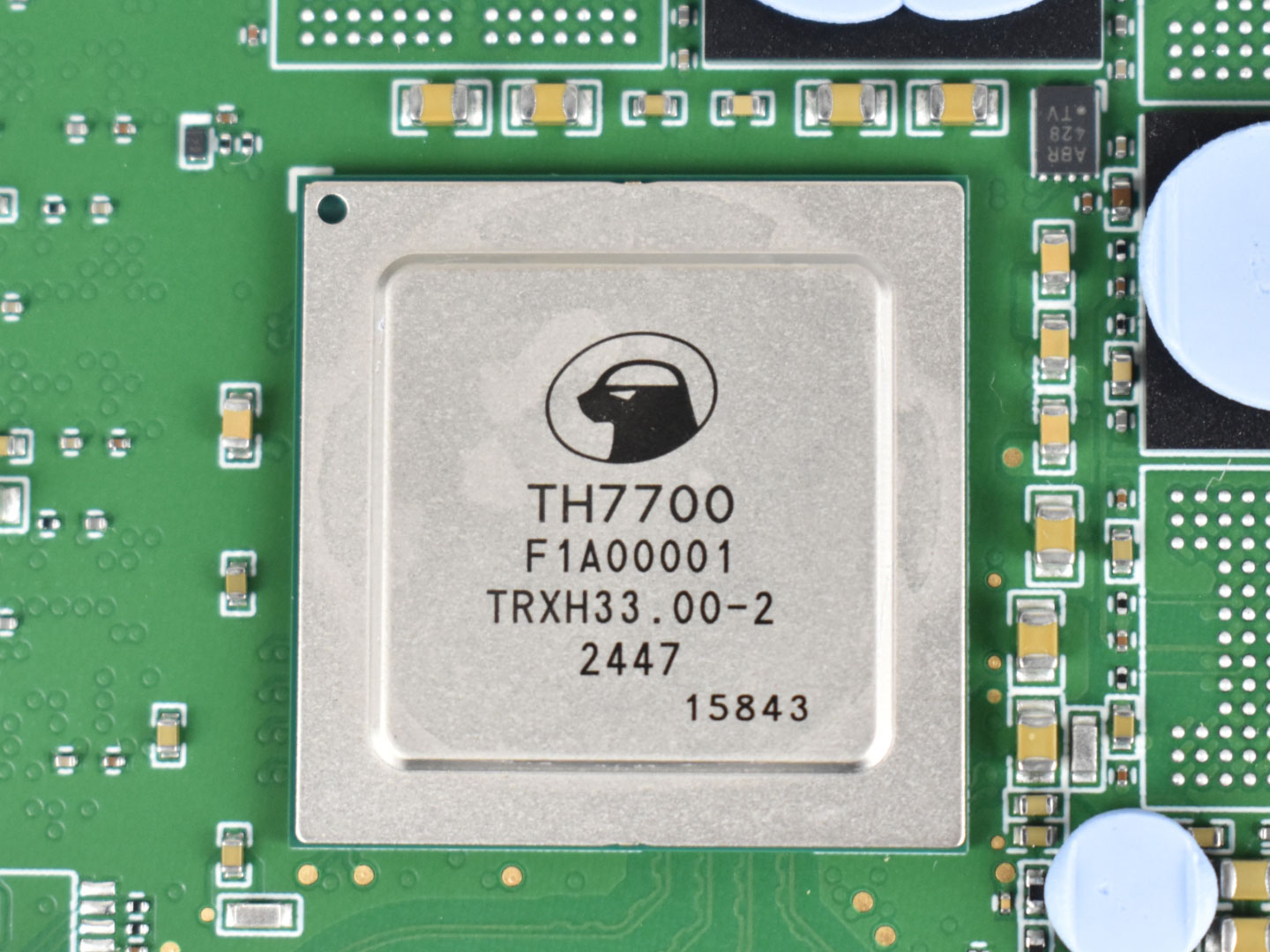
This SSD features an in-house developed controller from the Chinese company T-Head, a chip company from Alibaba, known as the Zhenyue 510 also labeled as "TH7700". It is a 16-channel controller built on TSMC's 12 nm FinFET process. The architecture is based on the T-Head 64-bit Xuantie R910, making it a RISC-V design, which sets it apart from most other SSD controllers we've analyzed that typically rely on Arm architectures. Additionally, it is equipped with 8 cores running at 1.6 GHz, providing strong computational capability for enterprise workloads.
Its 16 channels enable direct communication with the NAND flash at speeds of up to 1600 MT/s, a common value for controllers in this class. The controller also supports interleaving with up to four or eight chip enables per channel, improving parallelism and NAND access efficiency, although the precise number is unknown.
RISC-V cores, such as T-Head's Xuantie R910, are becoming increasingly common across the industry, appearing not only in SSD controllers but also in data center accelerators, IoT devices, networking equipment, and various embedded platforms. As an open-standard architecture, RISC-V offers greater flexibility and customization compared to traditional designs, allowing companies to tailor performance and features to specific workloads. This combination of scalability, efficiency, and architectural freedom makes it particularly well-suited for modern, high-performance and specialized hardware solutions.
DRAM Cache

The SSD comes equipped with a total of 5 DDR4 chips from the South Korean manufacturer SK Hynix, with 5 modules on the back side of the PCB. The specific model used is the H5AG46DXNDX117, which is a 16 Gb module (2 GB) supporting a bandwidth of up to 3200 MT/s CL-22, with a total of 10 GB of DRAM Cache.
NAND Flash
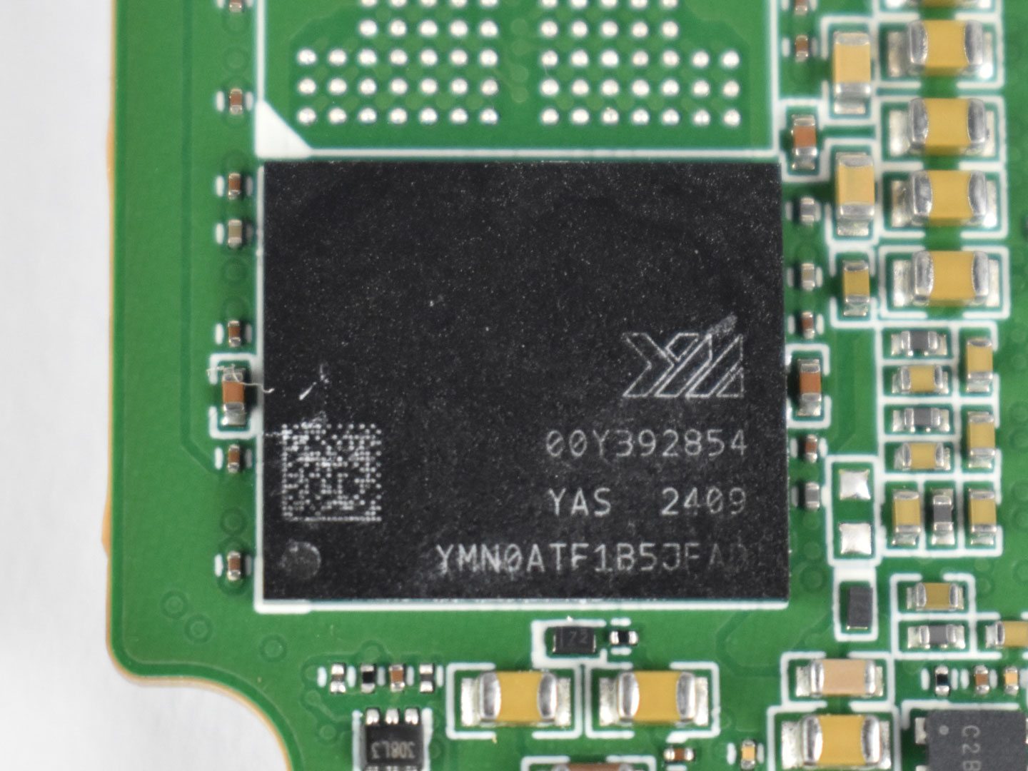
Our SSD features a total of 8 NAND packages, with 4 placed on each side of the PCB, along with 8 additional BGA-132 solder pads reserved for higher-capacity configurations. The NAND used in this design is manufactured by YMTC, specifically the 3D eTLC WDS X3-9070 EET1A 1 Tb 232-layer dies.
Each NAND die has a capacity of 128 GB, and with a total capacity of 8 TB, each package provides 1 TB, meaning that each NAND package contains 8 dies internally. The NAND is marked as YMN0ATF1B5JFAD, and each die measures approximately 68 mm², resulting in a storage density of around 15.1 Gb/mm²—an impressive figure for this generation, which is now being succeeded by newer YMTC designs such as the X4-9070 1 Tb TLC, X4-9060 512 Gb TLC, and their QLC variants.
These dies are capable of interfacing with the controller at speeds of up to 2400 MT/s, although actual performance depends on the controller's capabilities. In this case, the controller is limited to 1600 MT/s, which is typical for early PCIe Gen 5 controllers. However, thanks to its 16-channel architecture, it still has more than enough bandwidth to comfortably saturate a PCIe 5.0 x4 interface.
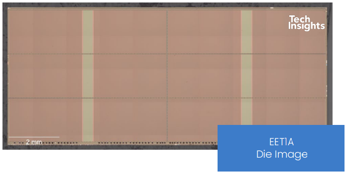
Structurally, these NANDs use two decks of 116 active storage layers combined with 21 dummy wordline layers alongside a 6-plane design alongside other supporting structures. Altogether, this achieves an array efficiency of over 91.7%. Higher array efficiency means less silicon area is wasted, improving cost-effectiveness and potentially delivering better performance relative to die size.
VRM - Power Circuitry
Just like any other electronic component we use in our daily lives, SSDs require power in order to operate. Graphics cards, processors, and motherboards all have voltage regulators to supply power to their respective circuits—and the power delivery for SSDs works in the same way. In the next section of our analysis we'll take a closer look at these details.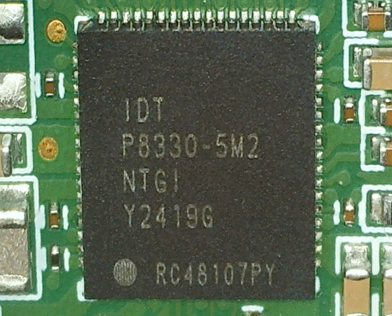
The main power management IC (PMIC) used here is the IDT P8330-5M2, designed by Integrated Device Technology—a subsidiary of Renesas. This PMIC is part of a dedicated power management solution for single or multichannel SSDs.
According to its block diagram, the chip supports up to six integrated step-down regulators, each with its own current and voltage configuration. These internal regulators use built-in MOSFETs and are tailored specifically for SSD applications. Additionally, the P8330-5M2 offers a wide range of protection features, including overcurrent, overvoltage, undervoltage, undercurrent, and over temperature safeguards—ensuring stable and reliable operation in high-performance environments.
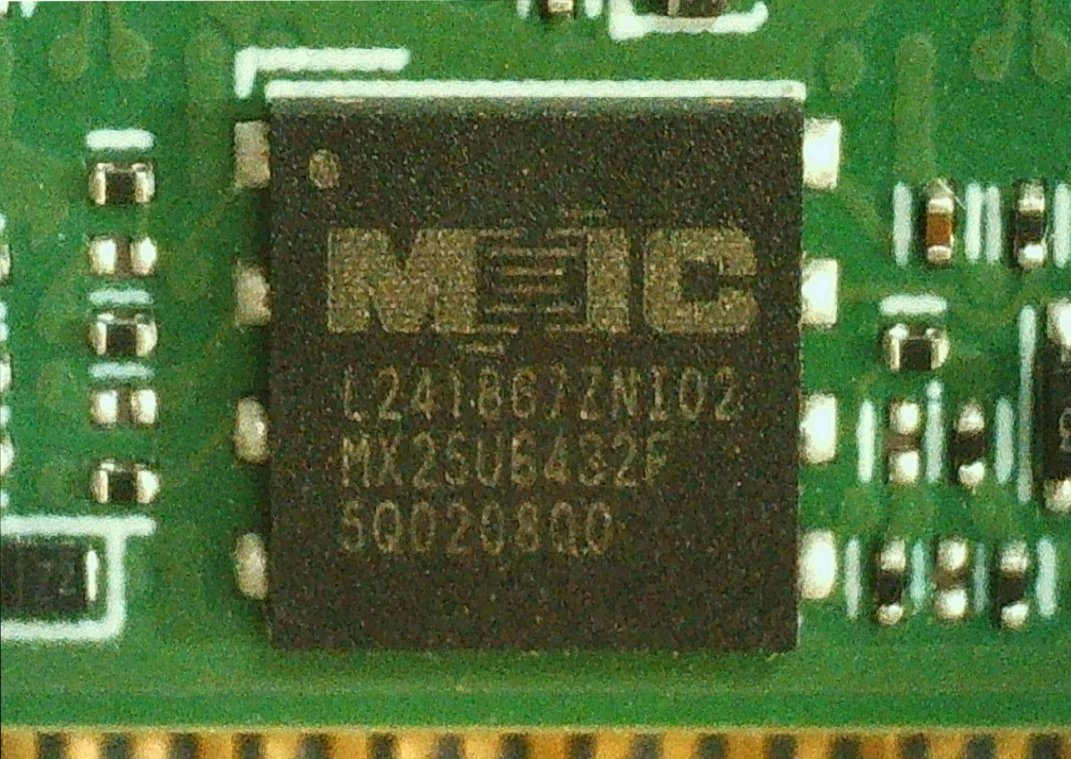
This IC, marked as MX25U6432F, is a 64 Mb SPI-NOR flash memory from Macronix. In SSD designs, NOR flash like this typically stores the bootloader—basic startup code that initializes the controller during power-on. Due to its limited storage capacity and slower write speeds, it does not hold the full firmware or data structures like the Flash Translation Layer (FTL) or wear-leveling logic. Those components reside within the NAND itself, often in dedicated pSLC areas to ensure higher reliability. The contents of this NOR chip are usually written during manufacturing and remain unchanged throughout the SSD's operational life.
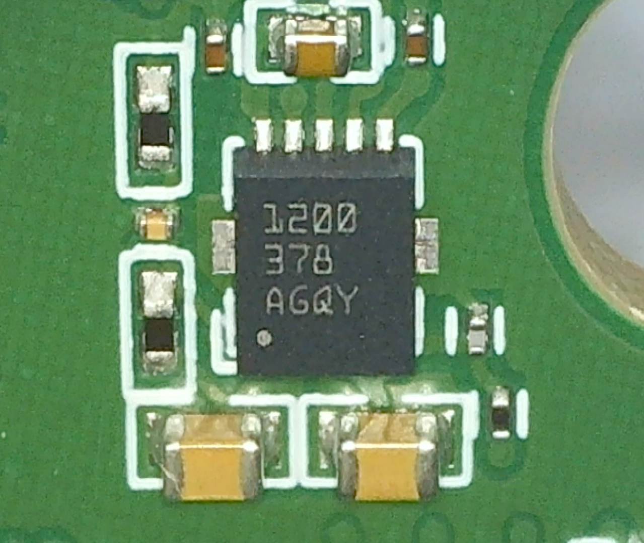
The TPS51200 from Texas Instruments is a sink and source termination regulator specifically designed for DDR memory applications. In SSDs, it plays a crucial role in managing the VTT termination voltage in DRAM modules, ensuring signal stability and data integrity during high-speed memory operations. It supports various DDR standards, including DDR2 through DDR4, and provides features like remote sensing, thermal shutdown, and fast transient response—all essential for reliable DRAM performance in enterprise-grade SSDs.
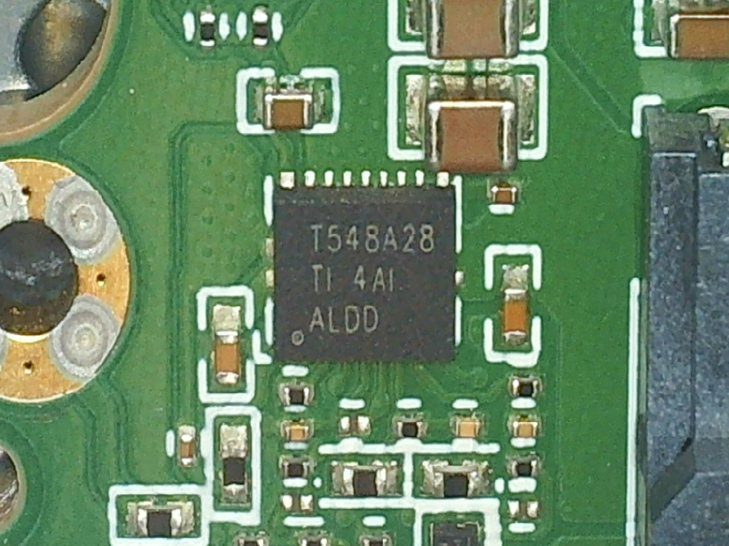
This component, marked TPS548A28, is manufactured by Texas Instruments and is a high-efficiency synchronous buck converter designed for demanding applications such as servers and data center systems. It supports a wide input voltage range from 2.7 V to 16 V and can deliver up to 15 A of output current, making it well-suited for powering critical rails within the SSD. Internally, it integrates low-resistance MOSFETs and features adaptive on-time (D-CAP3) control, enabling fast transient response and stable voltage regulation without requiring complex external compensation.
Power Loss Protection
Power loss protection in datacenter SSDs is essential to ensure data integrity during power failures. Using capacitors for temporary energy storage allows the safe completion of ongoing operations, preventing data corruption in critical environments. This ensures high availability and reliability of data.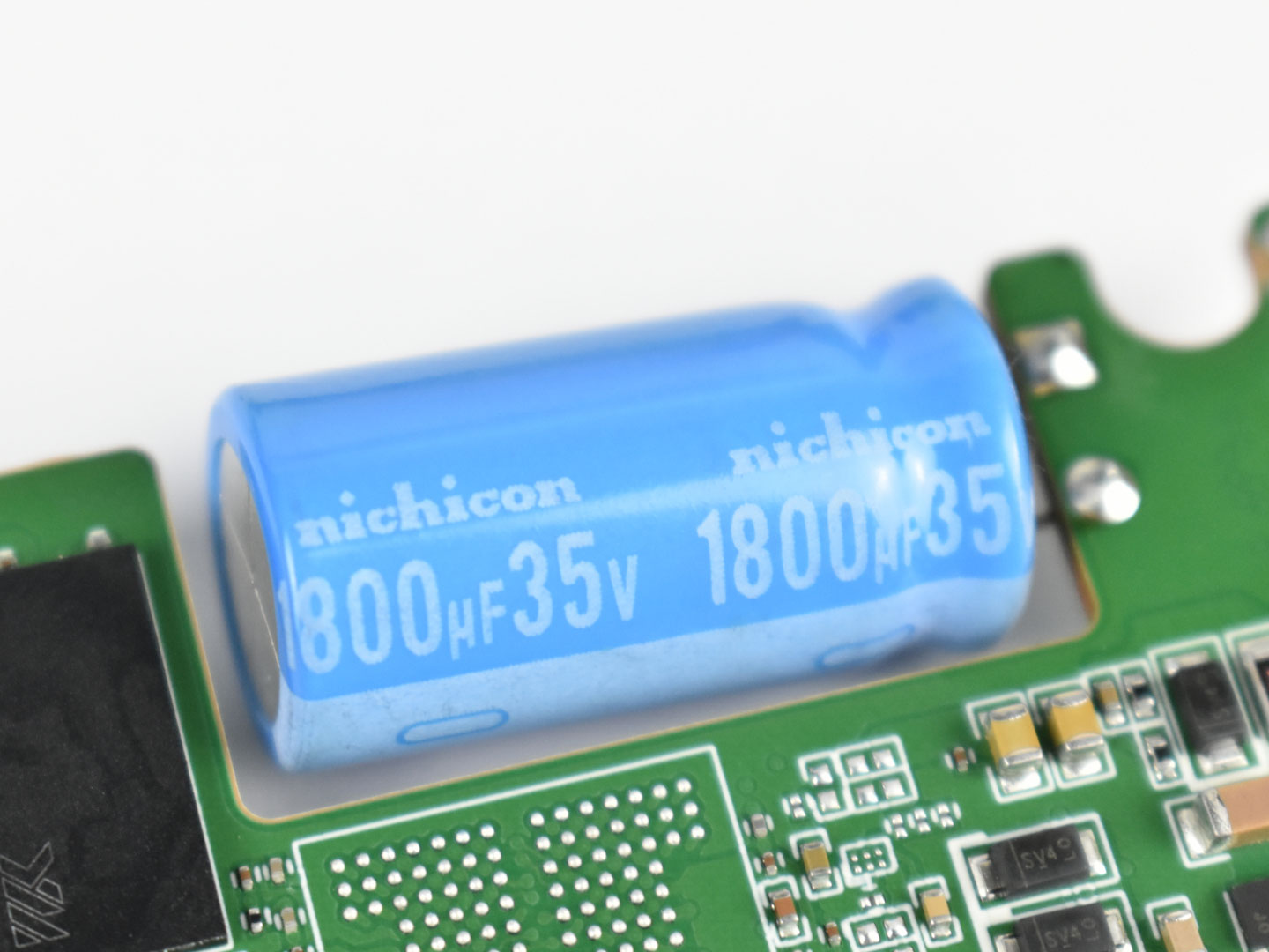
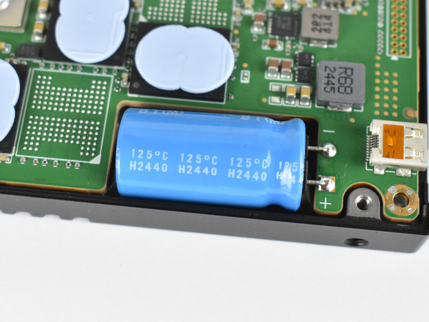
This SSD incorporates one aluminium electrolytic capacitor manufactured by Nichicon. That capacitor operates at a voltage of 35 V with a capacitance of 1800 µF, and is rated to withstand temperatures of up to 125°C.
Estimated Hold Up Time
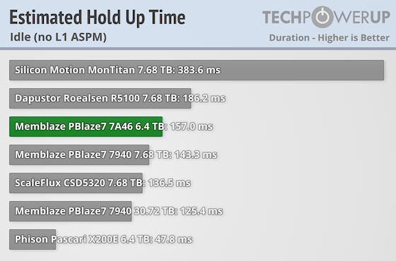
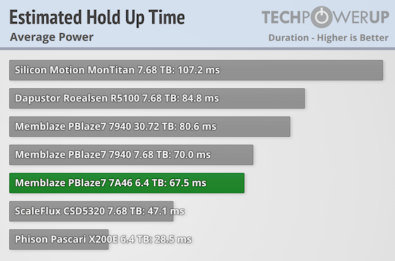
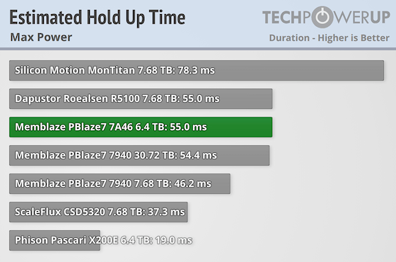
To estimate the hold-up time, we applied a set of equations that help approximate how long the drive can remain operational during an unexpected shutdown, based on its energy requirements. Our calculations use measured values for idle, average, and peak consumption. The analysis also considers the number and size of onboard capacitors, along with specific energy usage under various workload conditions.Please note: It's important to note that it's not an exact measurement, but rather a simplified calculation to illustrate how long an SSD might remain powered during a sudden power loss. In real-world conditions, power consumption is typically lower than the scenario shown here, which would result in a longer hold-up time.
Nov 20th, 2026 13:47 PST
change timezone
Latest GPU Drivers
New Forum Posts
- Honestly, do you care about GTA VI? (208)
- When you could finally run Crysis maxed out? (63)
- WarpCoreBench scores! (80)
- GTA VI (20)
- Anthrophics IPO (25)
- GeekMagic Ultra Smart WiFi Weather Station (8)
- Very unusual two gaming-pc scenarios. (35)
- Can i play GTA 6 now? (Joke) (14)
- How to prevent OLED burn damage due to PC freezes or power outtages? (47)
- Zen 3 IF/IMC degradation (239)
Popular Reviews
- AMD Zen 6 Technical Deep Dive
- Ugreen NASync DXP4800 GT Review
- Microsoft Surface Laptop Ultra Review - The Next-gen Arm Laptop
- Corsair RM1200e (Second Generation) Review
- Acemagic Retro X3 Review
- Upcoming Hardware Launches 2027 (Updated Nov 2026)
- Pulsar Office Tour & First Look at P1 Dual-Sensor Mouse
- Biwin Black Opal NV7400 2 TB Review
- AMD Ryzen 7 9800X3D Memory Performance Scaling
- AMD Ryzen 7 9800X3D Review - The Best Gaming Processor
TPU on YouTube
Controversial News Posts
- NVIDIA Co-Founder and CEO Jensen Huang Officially Resigns (490)
- Report: Jensen Huang Eyes NVIDIA Comeback (255)
- Open Letter Asking NVIDIA to Reinstate Jensen Huang Passes 115,000 Signatures (184)
- OpenAI CEO Argues Home PCs Waste the World's Limited DRAM Supply (152)
- NVIDIA Launches Investigation Into Jensen Huang's Relationship With Suspected Chinese Spy (136)
- Intel "Raptor Lake Next" 16-Core and 20-Core CPUs Surface (130)
- Legendary Game Studio BioWare Shuts Down Following EA Layoffs (104)
- Dell CEO Says the Memory Shortage Will Get Worse in 2027 (95)