 22
22
NZXT Switch 810 Review
Assembly & Finished Looks »A Closer Look - Inside
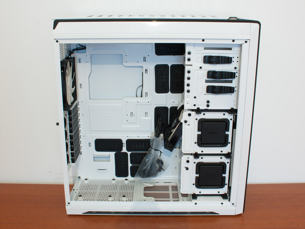

To gain access to the interior, simply remove two of the three thumb screws holding each side panel in place. The third one at mid-height is just supposed to be loosened as it acts as a spring loaded clip. Just like the exterior, the entire insides of the Switch 810 are colored to match. There are many black openings in the motherboard tray to ensure a clean interior. Even a small PCB on the backside means that you just need a single Molex connector to power up to six 3-pin equipped fans. With around 20 mm of space, cable management should not be an issue, if you choose to use some zip ties and spend time cleaning things up a bit.


Two hard drive cages in the front of the chassis are used to hold 2.5 and 3.5 inch storage devices. Held in place by thumb screws as well, you may remove each of these cages easily. A set of grips on the side makes this process extremely easy - just remember to detach any connected drives first. With all the cages removed, you can clearly see the four spots for 120/140 mm fans - two on the floor and two in the front of the chassis. You may even remove the bottom rail of the hard drive trays and install a radiator in here if you wish.
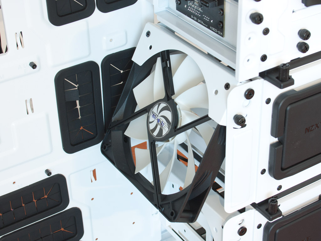

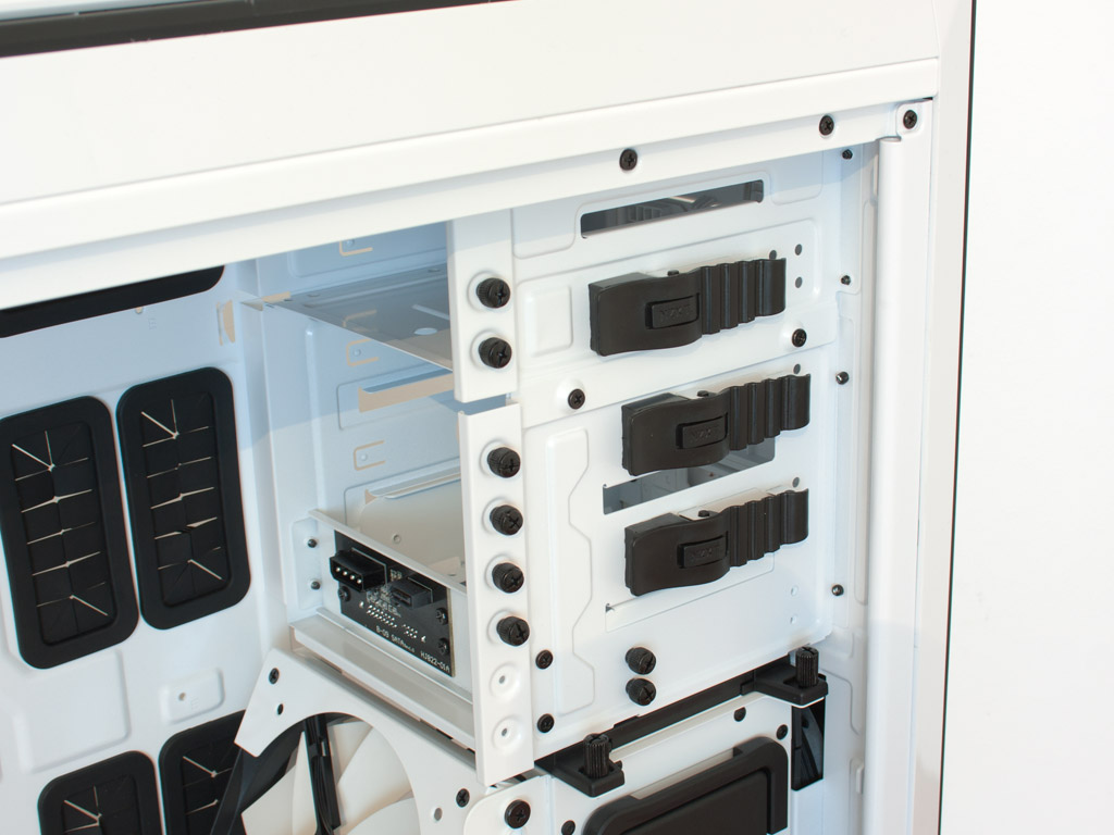
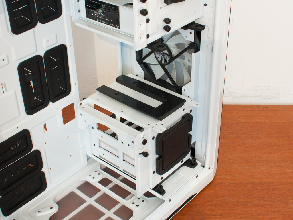
Each hard drive cage may hold a 120 or 140 mm fan, which can be angled to direct the air flow, but NZXT only includes a 140 mm one on the top cage. This brings the total number of 140 mm, 3-pin equipped units to four within the Switch 810. The hot-swap bay in the bottom 5.25 inch drive is implemented using a high-quality PCB instead of a simple plastic bar, while the rest of the bays come with the same screw-less locks we have seen in other NZXT cases as of late. The top one is pushed back a bit, allowing you to use the front cover properly.

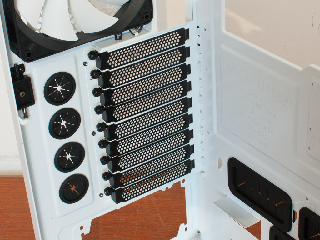

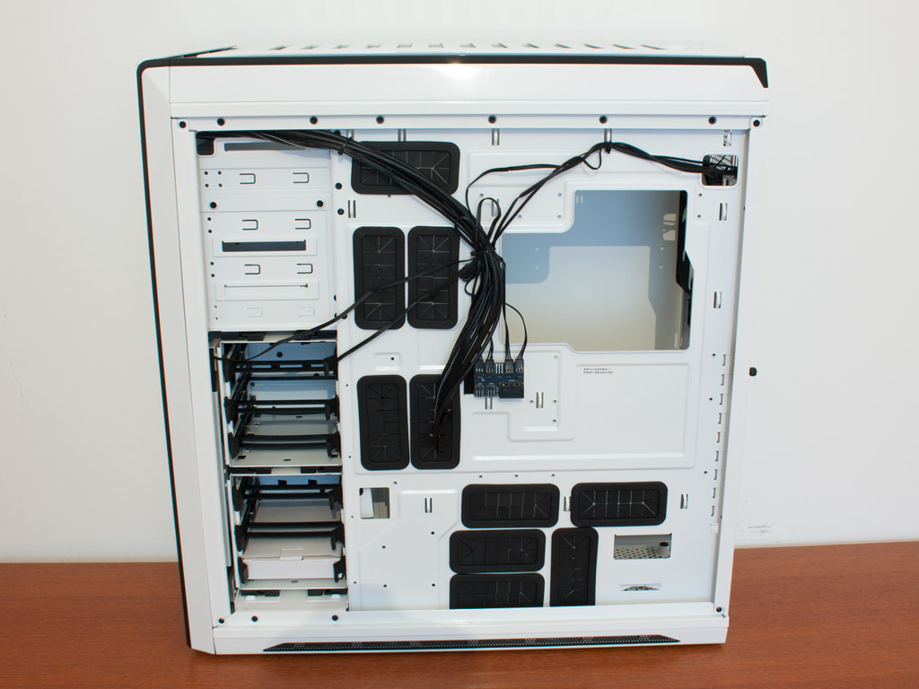
Turning our focus to the rear, the PSU bay is simple but effective, with six foam covered bumps on which the unit rests. Thanks to the spacious interior, you should have no issue with longer, high wattage units. Above that are the afore mentioned motherboard expansion slots with each cover held in place by a separate, black thumb screw. In the very top you can clearly see the white bladed, rear exhaust fan.

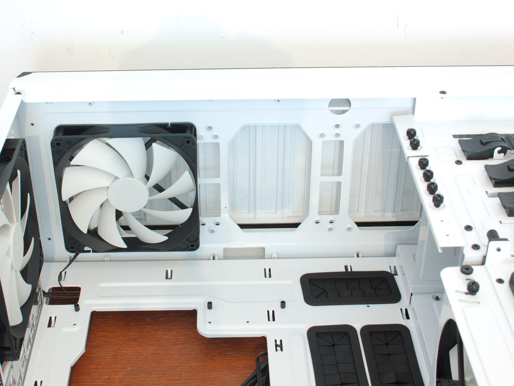
Due to the construction, you may install up to two 140 mm units in the floor of the chassis and still use the hard drive cage above the front cooling unit. The three spots in the ceiling are not obstructed in any way, so you should be fine to place a large radiator in this part of the chassis without having to sacrifice any expandability.
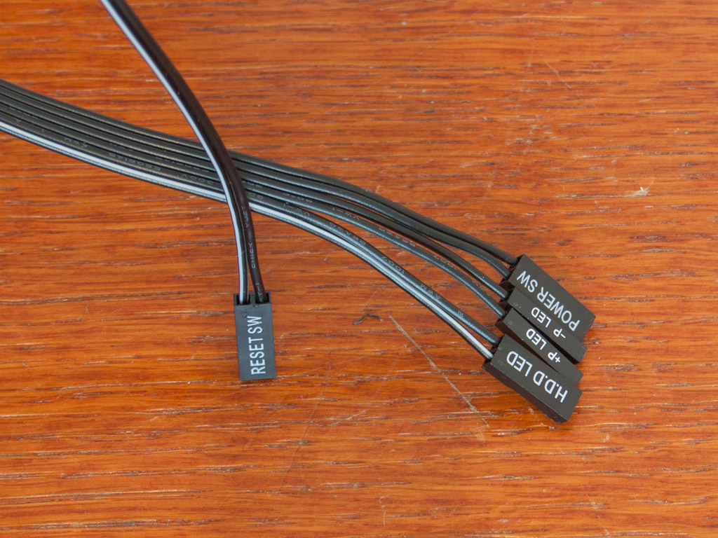
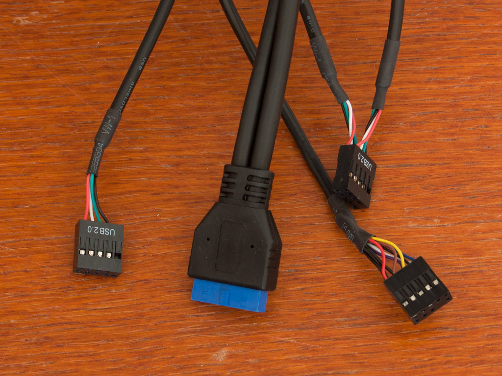

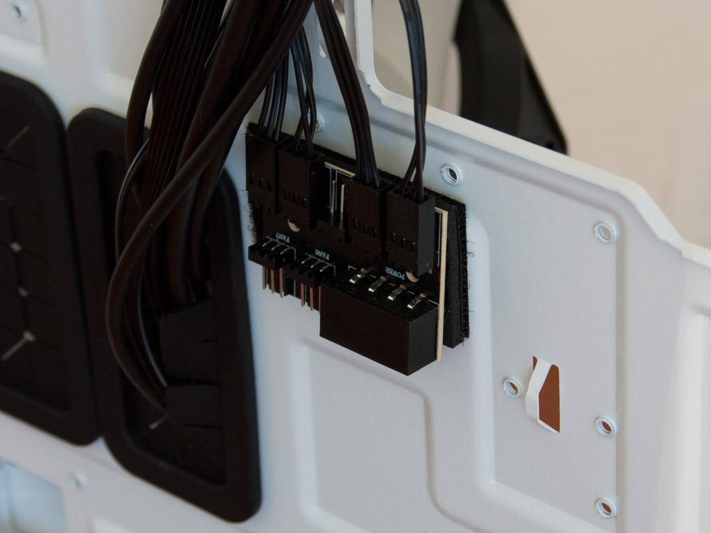
In terms of cabling, the Switch 810 does not really bare any surprises. The only connector which stands out is the SATA cable, which is needed to power the Light and I/O panel of the chassis.
Jul 30th, 2025 10:24 CDT
change timezone
Latest GPU Drivers
New Forum Posts
- What's your latest tech purchase? (24401)
- Looking To Make List Of Keyboard Manufacturers (29)
- AI Job Losses: let's count the losses up, total losses to AI so far 94,000 and counting (85)
- Post your 7-Zip v22.01 scores (439)
- 3DMARK "LEGENDARY" (349)
- 9070XT Bios Flashed Fail (8)
- RX6800XT Gigabyte Gaming OC not giving image while being on "OC" switch and even sometimes while being on "silent" switch. (21)
- Spoiler Alert........this car is fast. (255)
- Are UPS lithium LiFePO4 batteries finally as cheap as lead-acid? (53)
- Gigabyte graphic cards - TIM gel SLIPPAGE problem (171)
Popular Reviews
- Herman Miller Logitech G Embody Review - No Pain, No Gain
- MSI Claw 8 AI+ A2VM Review
- Lenovo Legion 5i (15IRX10) Review - Feature-Rich and Wallet Friendly
- Lian Li O11 Dynamic Mini V2 Review
- Upcoming Hardware Launches 2025 (Updated May 2025)
- Noctua NF-A12x25 G2 PWM Fan Review
- Sapphire Radeon RX 9060 XT Pulse OC 16 GB Review - An Excellent Choice
- AMD Ryzen 7 9800X3D Review - The Best Gaming Processor
- AQIRYS Sirius Pro Review
- NVIDIA GeForce RTX 5050 8 GB Review
TPU on YouTube
Controversial News Posts
- AMD's Upcoming UDNA / RDNA 5 GPU Could Feature 96 CUs and 384-bit Memory Bus (135)
- AMD Radeon RX 9070 XT Gains 9% Performance at 1440p with Latest Driver, Beats RTX 5070 Ti (131)
- Intel "Nova Lake-S" Core Ultra 3, Ultra 5, Ultra 7, and Ultra 9 Core Configurations Surface (110)
- DDR6 Memory Arrives in 2027 with 8,800-17,600 MT/s Speeds (101)
- AMD Sampling Next-Gen Ryzen Desktop "Medusa Ridge," Sees Incremental IPC Upgrade, New cIOD (97)
- Intel CEO Confirms SMT To Return to Future CPUs (95)
- NVIDIA Becomes First Company Ever to Hit $4 Trillion Market-Cap (94)
- Windows 12 Delayed as Microsoft Prepares Windows 11 25H2 Update (93)