 16
16
Seasonic G Series V2 550 W Review
Voltage Regulation, Hold-up Time & Inrush Current »A Look Inside & Component Analysis
Before reading this page, we strongly suggest a look at this article, which will help you understand the internal components of a PSU much better. Our main tool for the disassembly of the PSU is a Thermaltronics TMT-9000S soldering and rework station. It is of extreme quality and is equipped with a matching de-soldering gun. With such equipment in hand, breaking apart every PSU is like a walk in the park!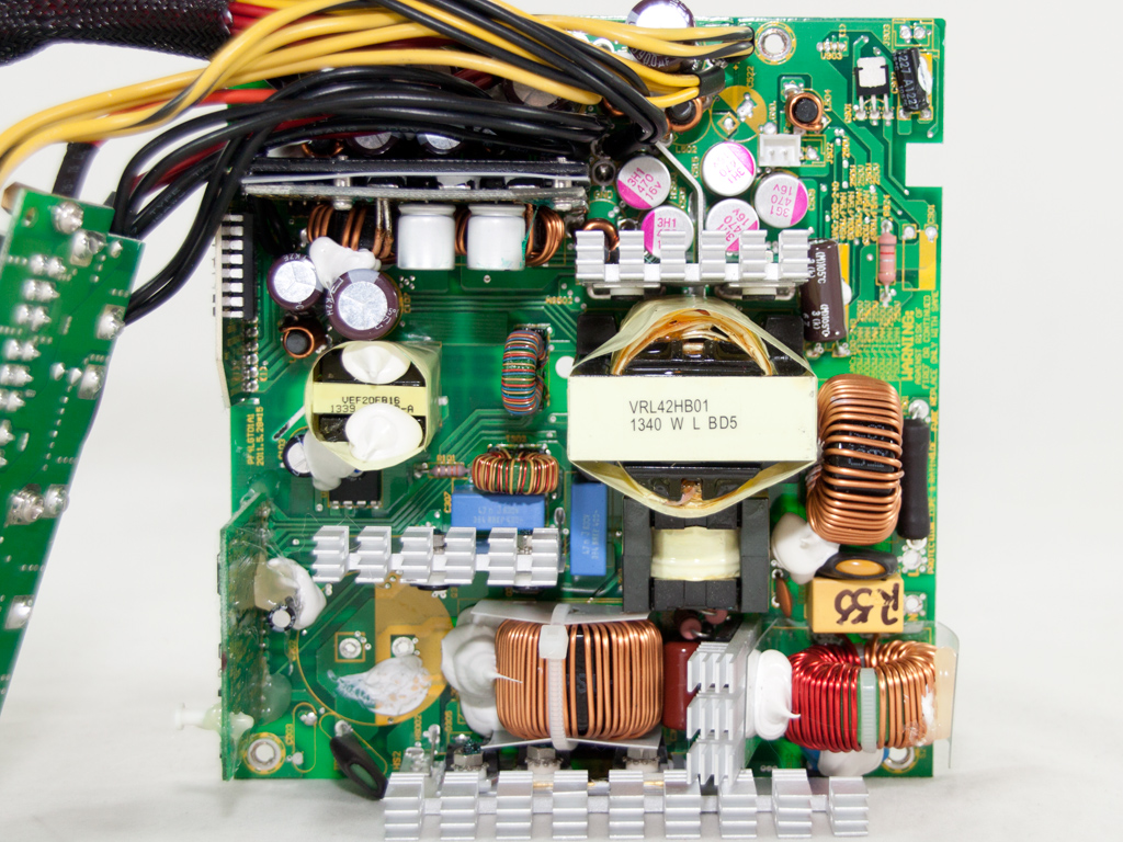

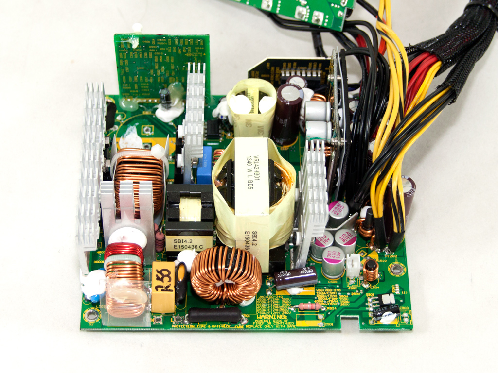


The platform looks like that of the older G-550 after a quick glance, so Seasonic only changed a few components. Simply read through the following paragraphs to figure out which ones. The primary side uses an LLC resonant converter to increase efficiency, while the secondary side uses two DC-DC converters with a semi-synchronous design for the rectification of the main rails, and as is stated on the box, lots of polymer filtering caps are used.
Behind the AC receptacle is a small PCB. It hosts four Y caps, one X cap, and a CM choke. The transient filter continues on the main PCB with two more CM chokes, two Y caps, a single X cap, and an MOV.


Like in the previous G-550 unit we reviewed, the heatsink holding the bridge rectifier is leaning off to one side. Some Seasonic engineers are apparently huge fans of Pizza's tower. A GBU10V08 is bolted to the heatsink. It can handle up to 10 A current.

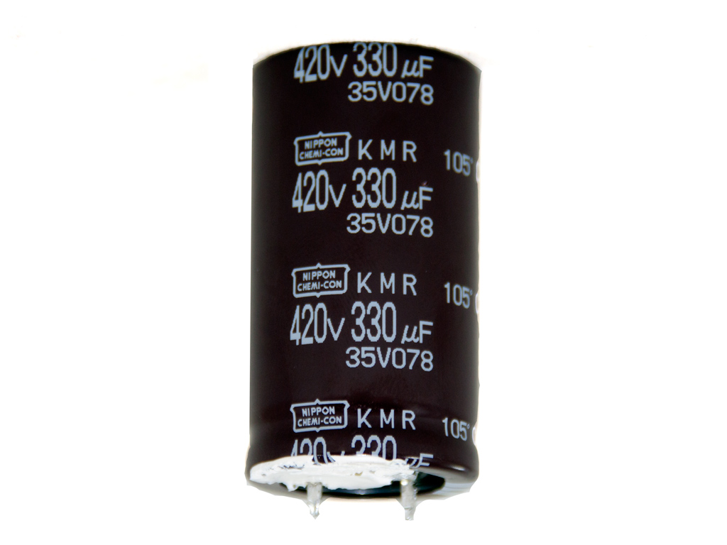

In the APFC, two Infineon IPP50R250CP fets and an STTH8S06D boost diode are used. The older G-550 used two Infineon SPP20N60C3 fets and a CREE C3D06060A boost diode instead. The hold-up cap is provided by Nippon Chemi-Con (330µF, 420V, 105°C, KMR series) and is smaller than the 390 µF cap in the previous G-550, although the cap's other specifications are the same. Right in front of it is the thermistor responsible for protection against large inrush currents.


This vertical daughter-board houses an ICE2HS01G resonant controller (large IC on the left) and an ICE3PCS01 PFC controller (small IC on the right).

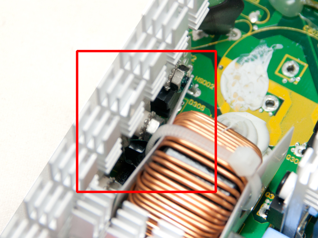
Two IPP50R250CP fets are used as primary switchers. Another major difference to the first G-550 is that a pair of MagnaChip MDF18N50 fets are used.


A semi-synchronous rectification scheme with two PSMN2R6-40YS fets and two SBR10U45 Schottky diodes rectifying the +12V rail is utilized in the secondary side. All the above are installed on the solder side of the main PCB. A heatsink on the component side helps lower their operational temperature. The minor rails are generated by two DC-DC converters.


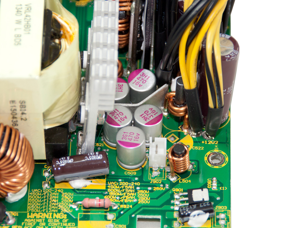
Several polymer Enesol and Chemi-Con caps are responsible for ripple suppression (105°C, KZE & KY series).


The standby PWM controller is an Infineon ICE2QR4765 IC. The Schottky diode responsible for the rectification of the 5VSB rail is an SBR10U45, and it is located on the solder side of the main PCB.


The supervisor IC is a SITI PS223 with support for OTP (Over Temperature Protection) out of the box.


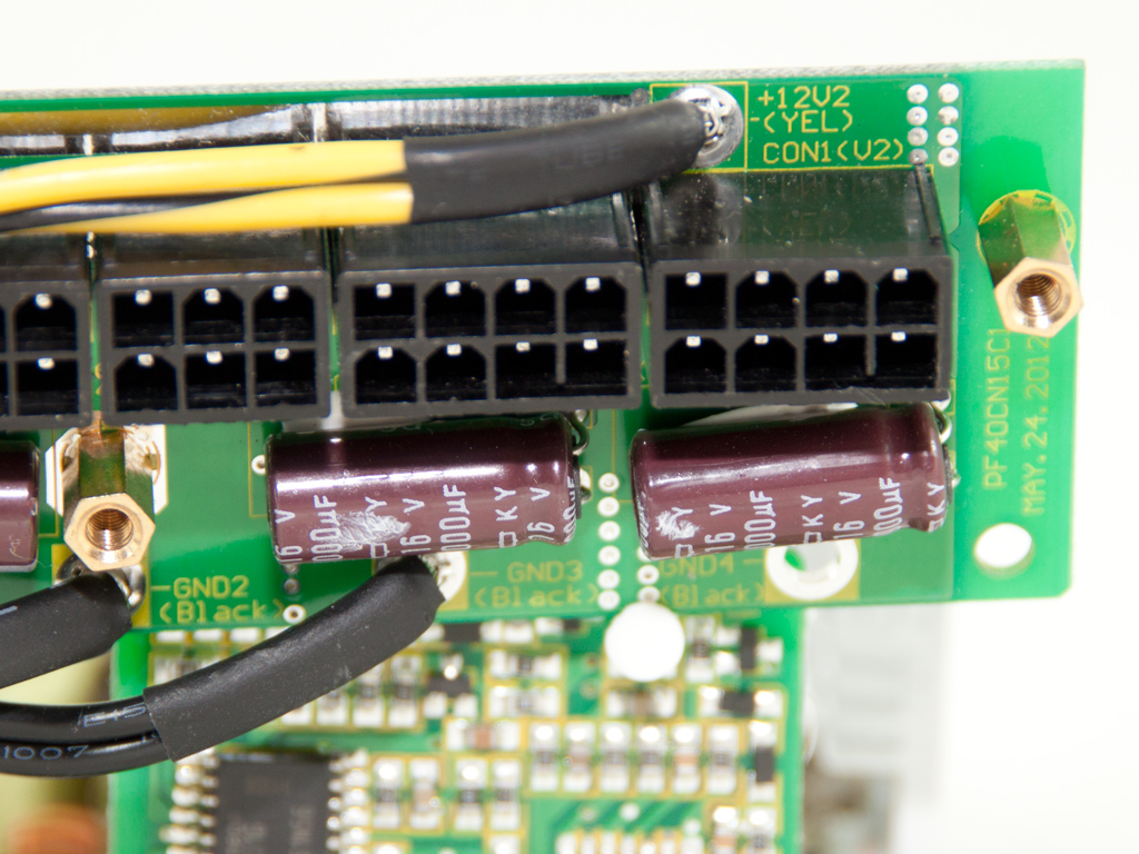

On the front of the modular PCB are four Chemi-Con caps that provide some extra ripple filtering to the outputs.


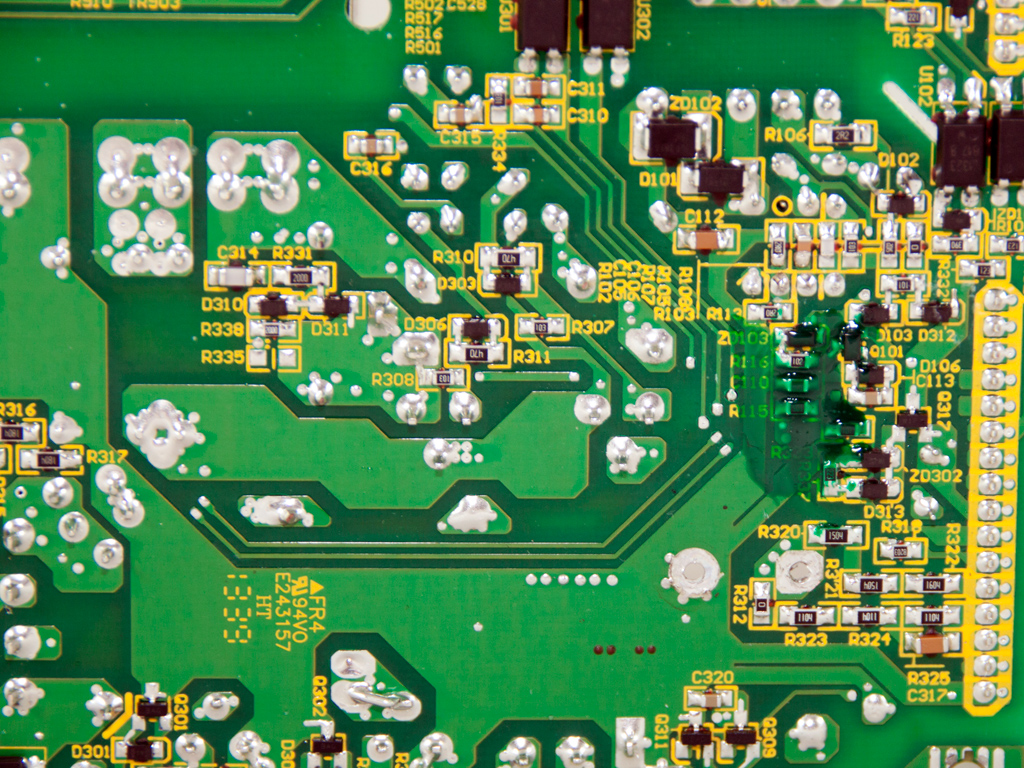

Soldering quality on the main PCB is quite good.


The cooling fan is provided by Jamicon, and its model number is KF1225B1HR-R (120 mm, 12 V, 0.35 A, 2200 RPM max, 75,000 MTBF, 81.17 CFM). This is another change over the old G-550 since it uses an ADDA fan with similar specifications.
Apr 25th, 2024 02:09 EDT
change timezone
Latest GPU Drivers
New Forum Posts
- The TPU UK Clubhouse (24784)
- (Anti) SFF fun house (349)
- Github comments used to push malware via Microsoft repo urls (1)
- What's your latest tech purchase? (20337)
- The Official Linux/Unix Desktop Screenshots Megathread (694)
- XFX RX470 8GB no video and error 43 (27)
- Cinebench crashed my PC. My Wi-Fi stopped working, and I keep getting a "Please wait" screen when I boot up my PC. (31)
- im new to throttelstop and i think i messed it up by copying others any hints would be very much aprreciated (1)
- Aida64 cache mem OC (7)
- I am getting artifacting when I change Windows security settings. Is my GPU failing, or is this just a Windows issue? (10)
Popular Reviews
- Fractal Design Terra Review
- Thermalright Phantom Spirit 120 EVO Review
- Corsair 2000D Airflow Review
- Minisforum EliteMini UM780 XTX (AMD Ryzen 7 7840HS) Review
- ASUS GeForce RTX 4090 STRIX OC Review
- NVIDIA GeForce RTX 4090 Founders Edition Review - Impressive Performance
- ASUS GeForce RTX 4090 Matrix Platinum Review - The RTX 4090 Ti
- MSI GeForce RTX 4090 Suprim X Review
- MSI GeForce RTX 4090 Gaming X Trio Review
- Gigabyte GeForce RTX 4090 Gaming OC Review
Controversial News Posts
- Sony PlayStation 5 Pro Specifications Confirmed, Console Arrives Before Holidays (116)
- NVIDIA Points Intel Raptor Lake CPU Users to Get Help from Intel Amid System Instability Issues (106)
- AMD "Strix Halo" Zen 5 Mobile Processor Pictured: Chiplet-based, Uses 256-bit LPDDR5X (101)
- US Government Wants Nuclear Plants to Offload AI Data Center Expansion (98)
- Windows 10 Security Updates to Cost $61 After 2025, $427 by 2028 (84)
- Developers of Outpost Infinity Siege Recommend Underclocking i9-13900K and i9-14900K for Stability on Machines with RTX 4090 (84)
- TechPowerUp Hiring: Reviewers Wanted for Motherboards, Laptops, Gaming Handhelds and Prebuilt Desktops (78)
- AMD's RDNA 4 GPUs Could Stick with 18 Gbps GDDR6 Memory (74)