 18
18
Seasonic Platinum Series 1200 W Review
Voltage Regulation, Hold-up Time & Inrush Current »A Look Inside & Component Analysis
Before reading this page, we strongly suggest a look at this article, which will help you understand the internal components of a PSU much better. Our main tool for the disassembly of the PSU is a Thermaltronics TMT-9000S soldering and rework station. It is of extreme quality and is equipped with a matching de-soldering gun. With such equipment in hand, breaking apart every PSU is like a walk in the park!


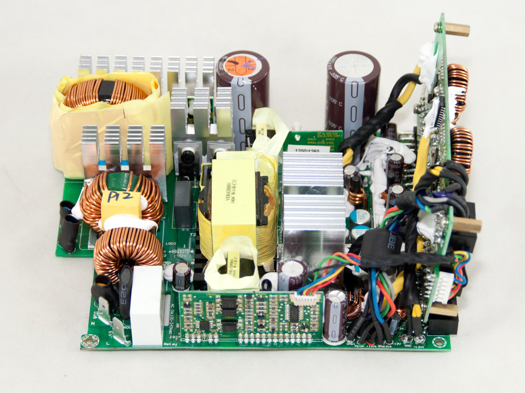
This unit uses Seasonic's current flagship platform, the XP3. Cooler Master was one of the first companies to use this platform, with slight differences resulting in a different fan and different bulk caps. The primary side uses a full-bridge topology and an LLC converter for lossless switching, and the secondary side employs a synchronous design with the +12V fets on the main PCB. Both DC-DC converters are also on the modular PCB to decrease power losses.
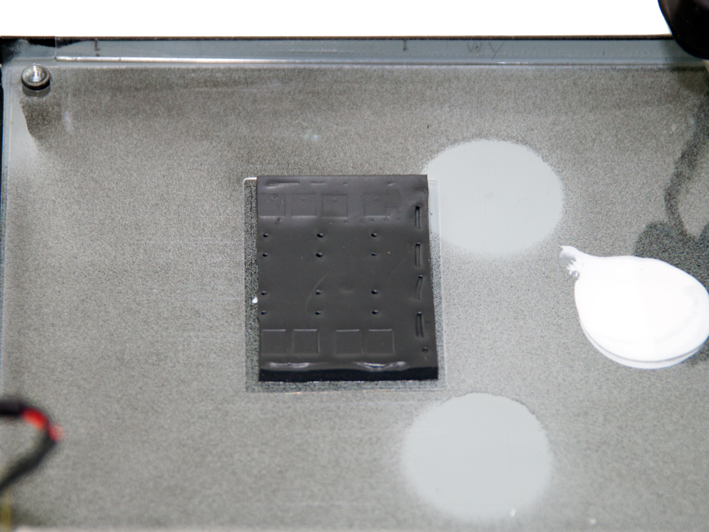
The sealed PCB behind the AC receptacle holds a CM choke, four Y caps, and a single X cap. The filter's other components, two pairs of X and Y caps, two CM chokes, and an MOV, are on the main PCB. There is also an NTC thermistor. It protects the unit against large inrush currents and has a relay that isolates it once it finishes its job.
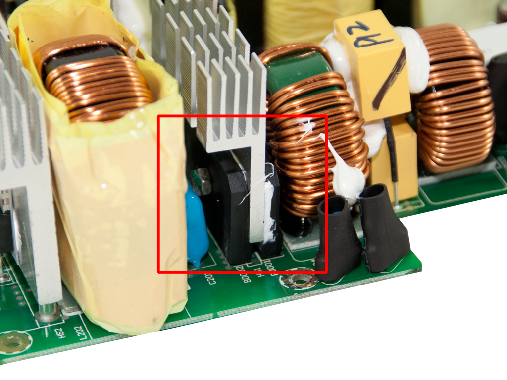

Both parallel bridge rectifiers are bolted to a dedicated heatsink.

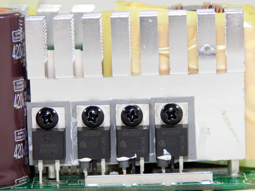

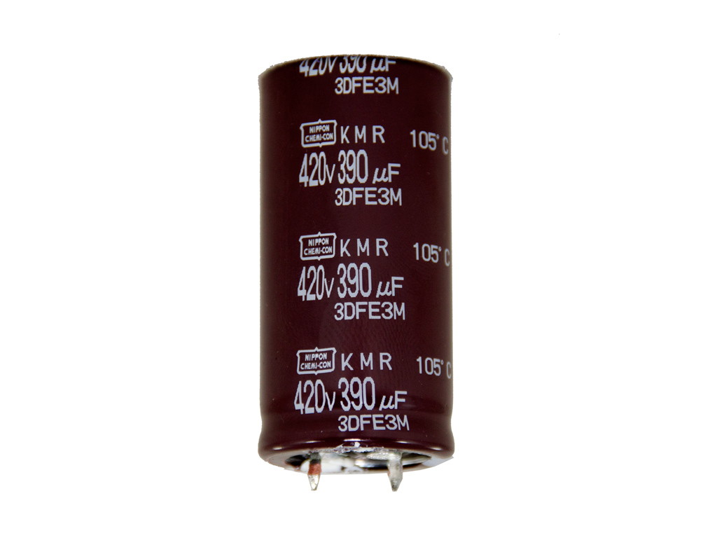
The APFC converter uses three Infineon IPP60R125CP fets and a single SCS110AG boost diode. The three parallel hold-up caps are provided by Nippon Chemi-Con (420 V; 390 μF each or 1170 μF combined; 105°C; KMR series).
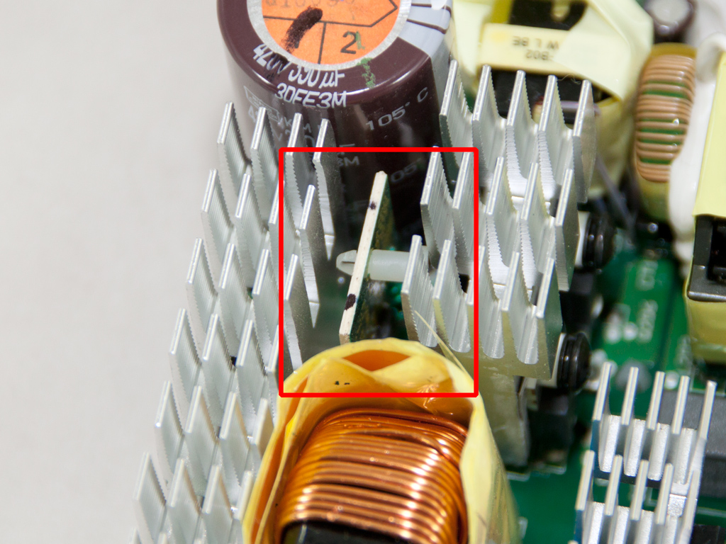
The PFC controller, an NPC1654 IC, is on a small vertical PCB, right between the primary heatsinks and the APFC.
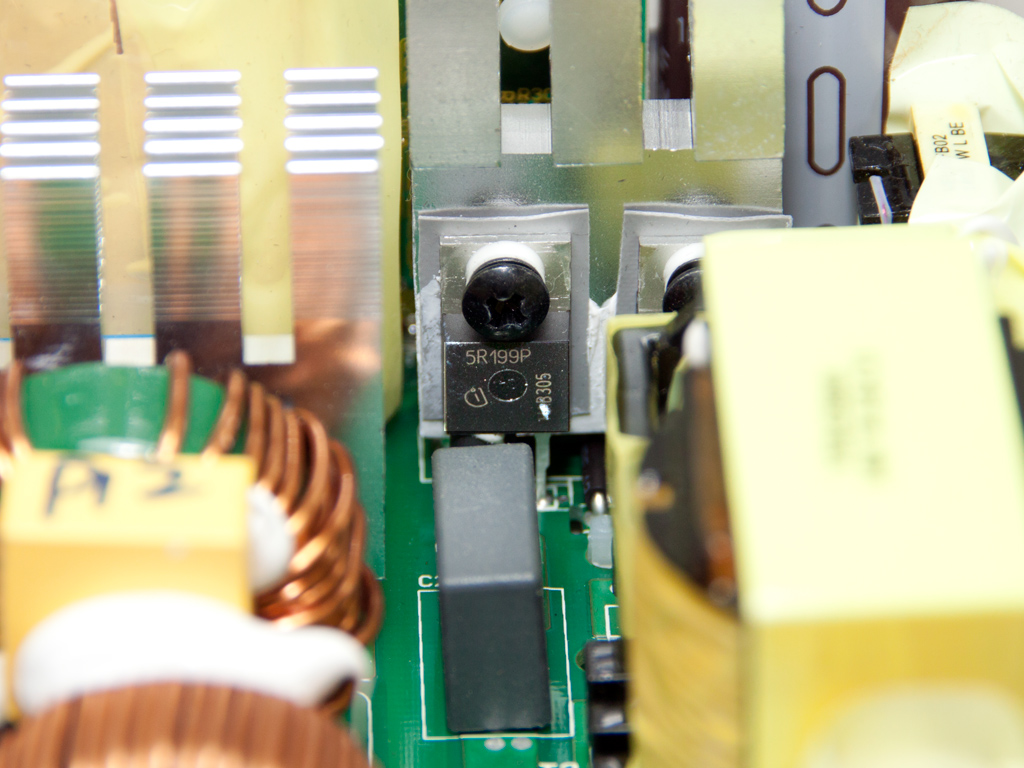
The full-bridge topology uses four Infineon IPP50R199CP fets. An LLC resonant converter is also used to boost efficiency.

The LLC resonant controller, a Champion CM6901 IC, is hiding behind the middle bulk-cap, but we desoldered the latter to clear the view.
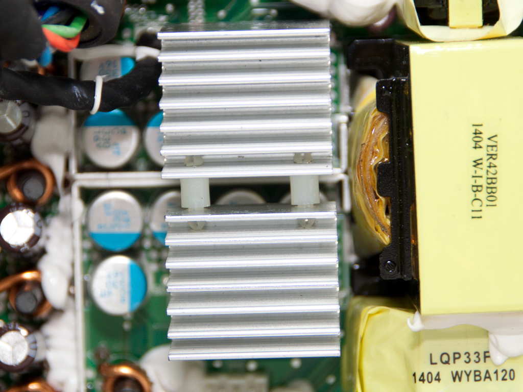
A large heatsink in the secondary side. It, however, doesn't host any mosfets. The aforementioned heatsink is obviously there to cool the +12V fets on the main PCB's solder side. There are eight such Fairchild FDMS015N04B fets in total. This heatsink and the enclosure itself keep these fets cool.
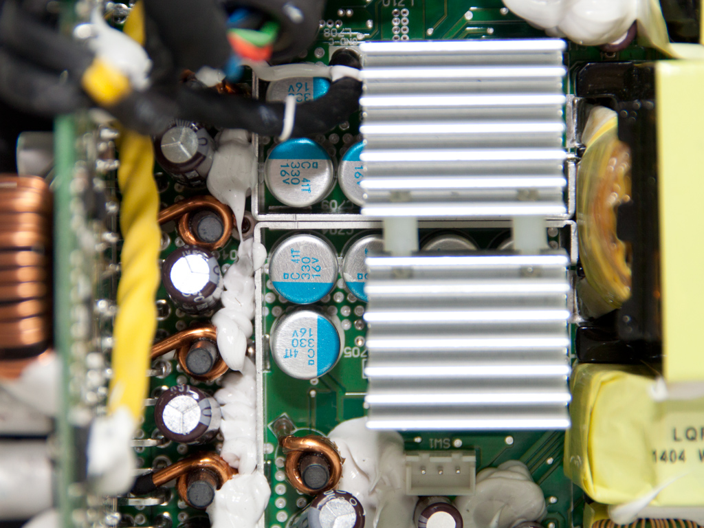
All capacitors in the secondary side, polymer and electrolytic, are provided by Nippon Chemi-Con, so they are of very good quality.
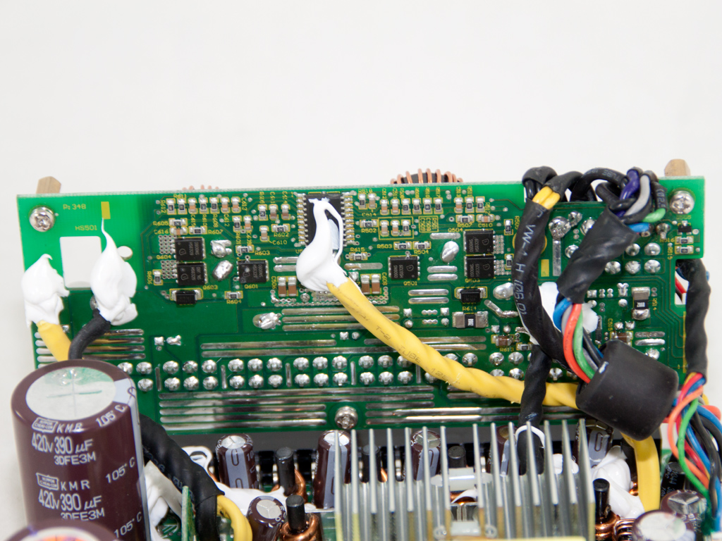
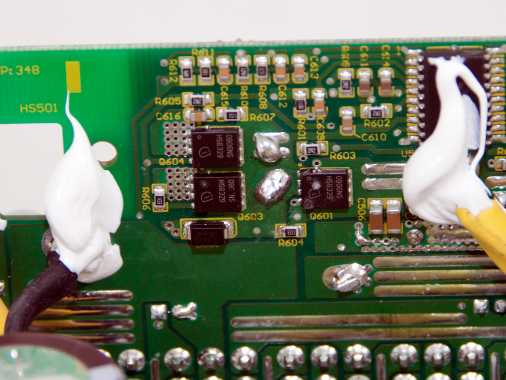

Both VRMs responsible for generating the minor rails are on the modular PCB, which minimizes energy losses. Each VRM has three Infineon BSC0906NS fets, and one APW7159 PWM controller handles both regulators.

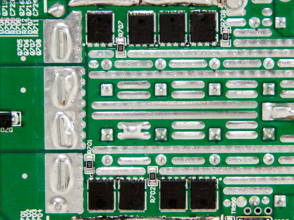
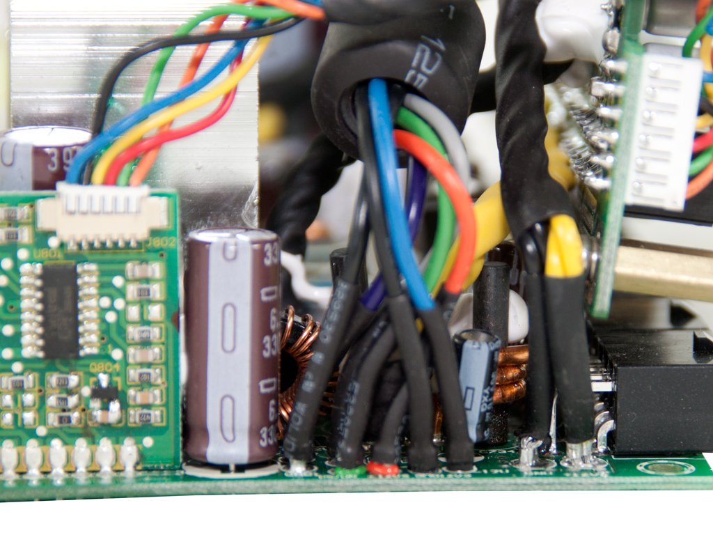
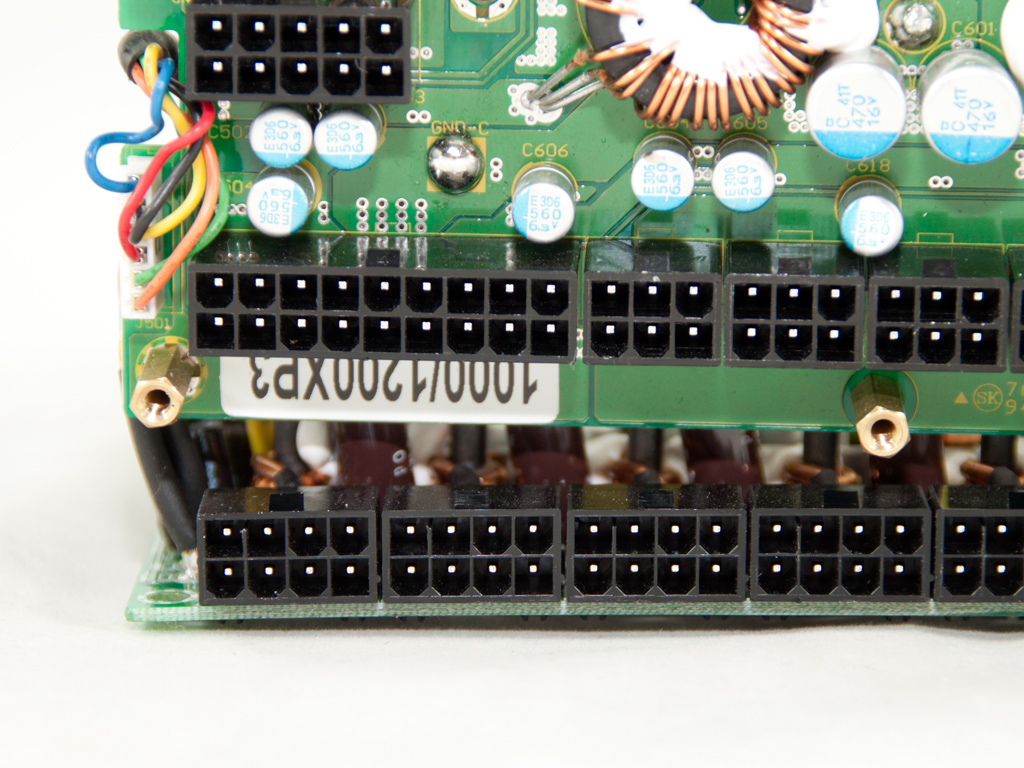
All lower modular sockets are directly soldered to the main PCB via thick metal conductors that reduce energy losses, which increases efficiency.

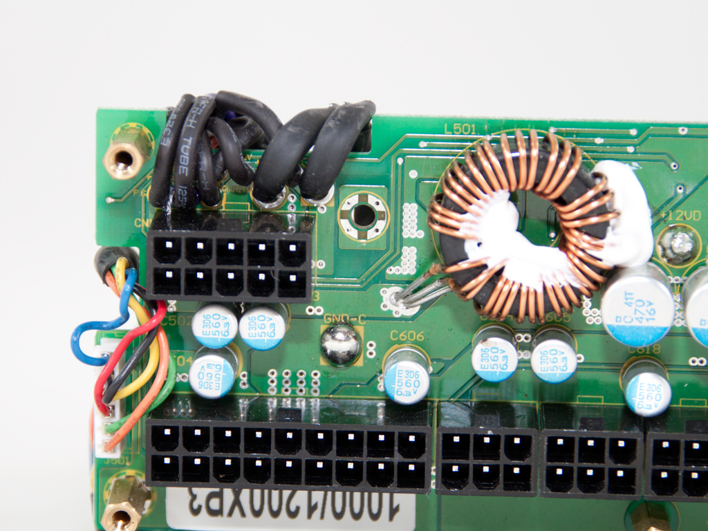
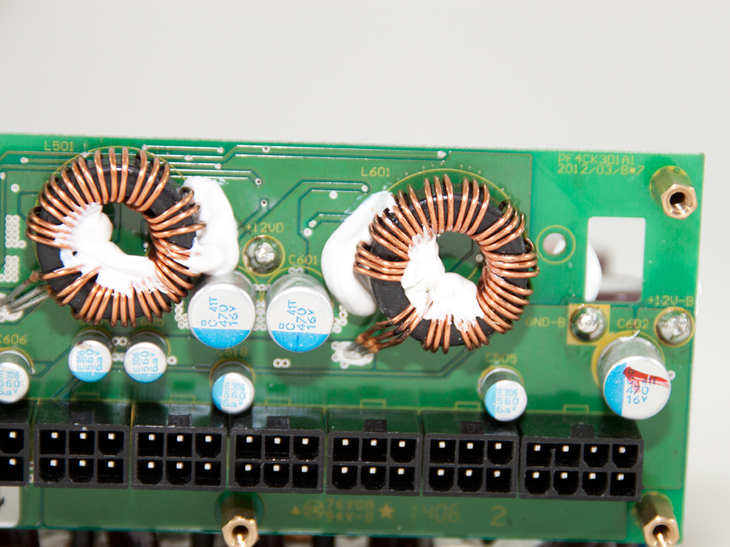
Many polymer caps on the modular PCB's primary side filter the rails, along with two coils which are used by both VRMs.
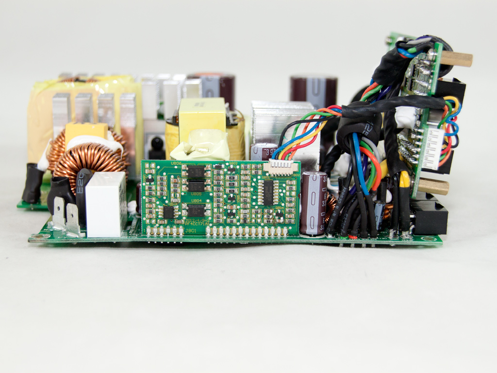

This board holds the supervisor IC, a Weltrend WT7257V and an AS393 dual-voltage comparator. The WT7257V supports OCP for up to two +12V virtual rails, but the Platinum-1200 only has one.

The standby PWM controller is an ICE2QR4765 IC, and it was buried under lots of glue in our sample.


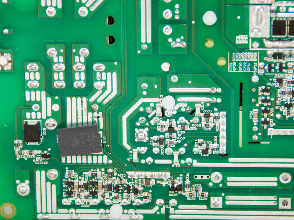
Soldering quality is very good, but we don't expect anything less from Seasonic.
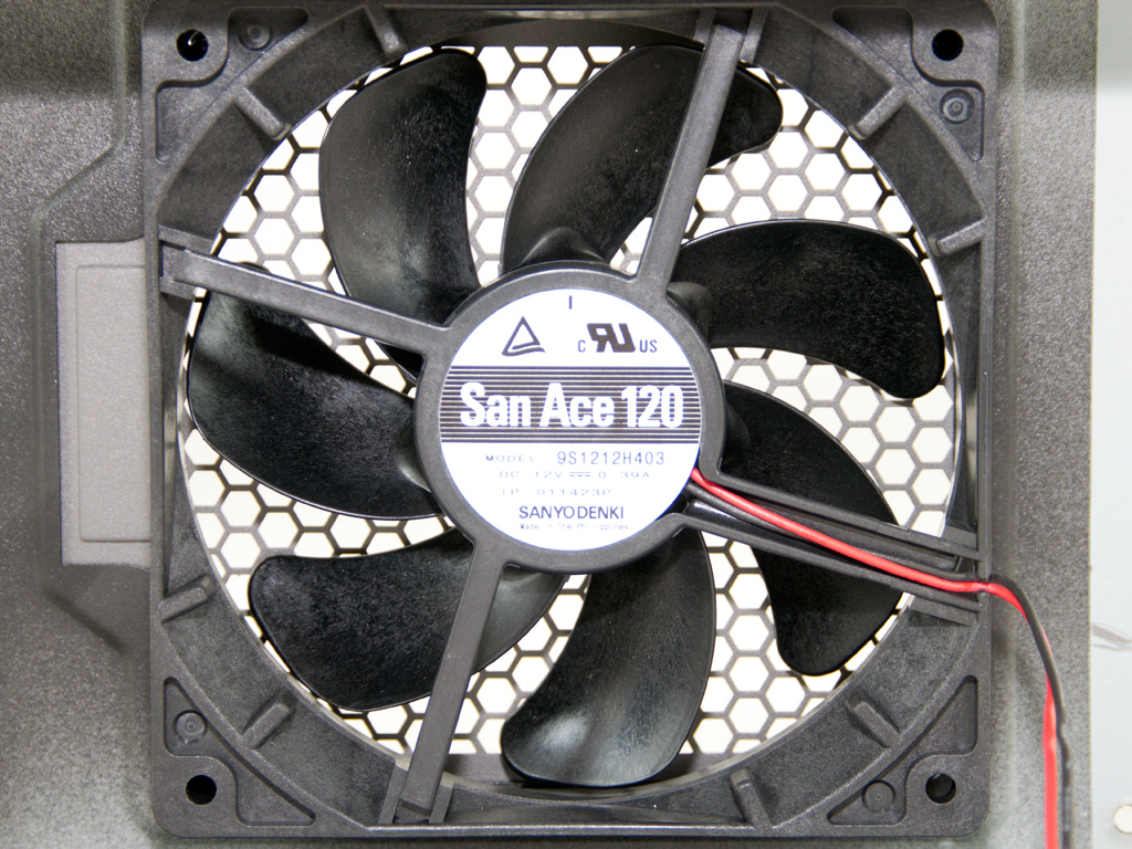

The cooling fan with model number 9S1212H403 is provided by Sanyo Denki and uses probably an improved (enhanced) sleeve-bearing, which will have it last a long time (40,000 hours according to its manufacturer).
May 13th, 2024 12:30 EDT
change timezone
Latest GPU Drivers
New Forum Posts
- Have you got pie today? (16335)
- Purchased an AX1200i PSU as part of some forward planning, what tier is this PSU? (69)
- Dell Workstation Owners Club (3082)
- How we ended with 16x9 Aspect ratios (2)
- vega 64 gpu frequency problem (9)
- Xeon Owners Club (8705)
- Milestones (13883)
- WCG Daily Numbers (12515)
- Last game you purchased? (286)
- TPU's Rosetta Milestones and Daily Pie Thread (1879)
Popular Reviews
- ZMF Caldera Closed Planar Magnetic Headphones Review
- Corsair MP700 Pro SE 4 TB Review
- Homeworld 3 Performance Benchmark Review - 35 GPUs Tested
- Bykski CPU-XPR-C-I CPU Water Block Review - Amazing Value!
- ThundeRobot ML903 NearLink Review
- Upcoming Hardware Launches 2023 (Updated Feb 2024)
- CHERRY XTRFY M64 Pro Review
- AMD Ryzen 7 7800X3D Review - The Best Gaming CPU
- ASUS Radeon RX 7900 GRE TUF OC Review
- Corsair iCUE Link RX120 RGB 120 mm Fan Review
Controversial News Posts
- Intel Statement on Stability Issues: "Motherboard Makers to Blame" (266)
- AMD to Redesign Ray Tracing Hardware on RDNA 4 (224)
- Windows 11 Now Officially Adware as Microsoft Embeds Ads in the Start Menu (172)
- NVIDIA to Only Launch the Flagship GeForce RTX 5090 in 2024, Rest of the Series in 2025 (152)
- Sony PlayStation 5 Pro Specifications Confirmed, Console Arrives Before Holidays (119)
- AMD's RDNA 4 GPUs Could Stick with 18 Gbps GDDR6 Memory (114)
- AMD Hits Highest-Ever x86 CPU Market Share in Q1 2024 Across Desktop and Server (111)
- AMD Ryzen 9 7900X3D Now at a Mouth-watering $329 (104)