 5
XMG Pro 16 (M25) Review - The Mini LED Rocketship
Display Testing »Disassembly and Teardown
The XMG Pro 16 (M25) has a lot in common with the XMG Pro 16 (E25), and that's why the teardown process is practically the same.
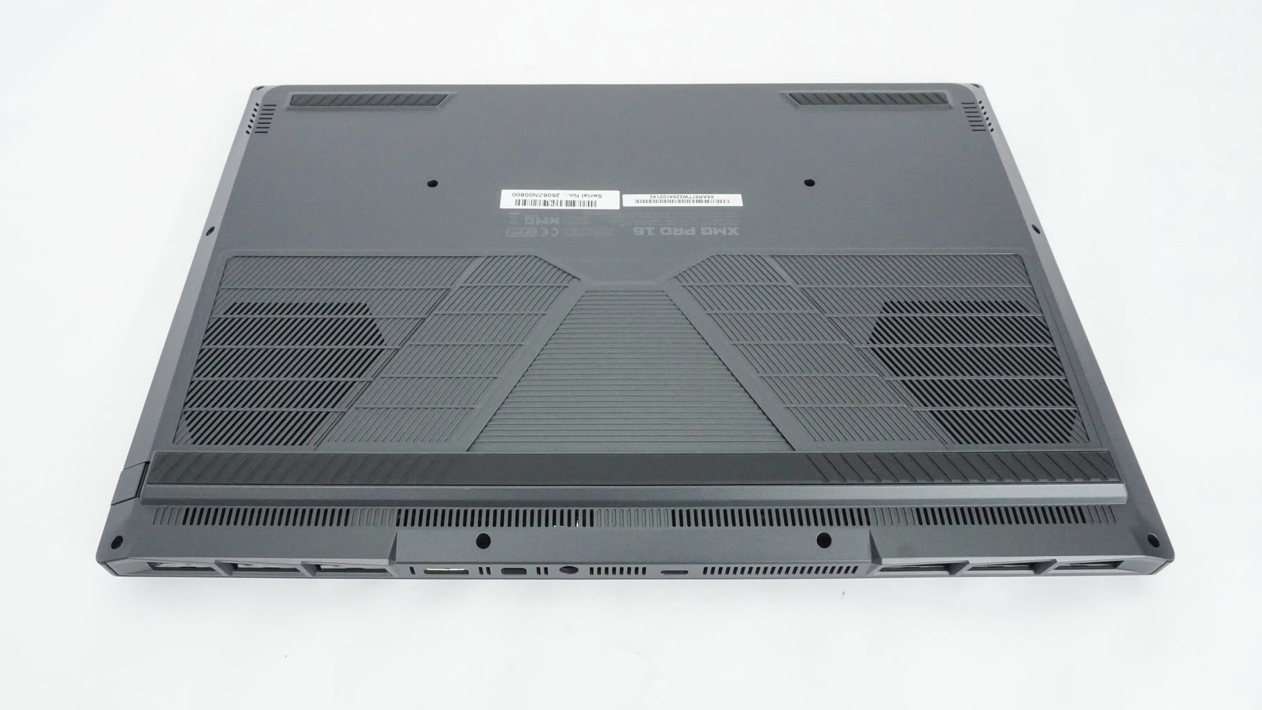
The bottom panel is held in place by twelve Phillips-head screws. As with many other XMG and Schenker laptops, the easiest way to pry off the cover is by popping the back vents. Hold and pop them with both hands and apply a bit of pressure using the backs of your wrists. If popping both at once feels too difficult, you can take the safer route and do them one at a time. After that, the panel should almost fully unclip—just lift the remaining three sides with your fingers. If any internal clips stay stuck, use a thin prying tool.
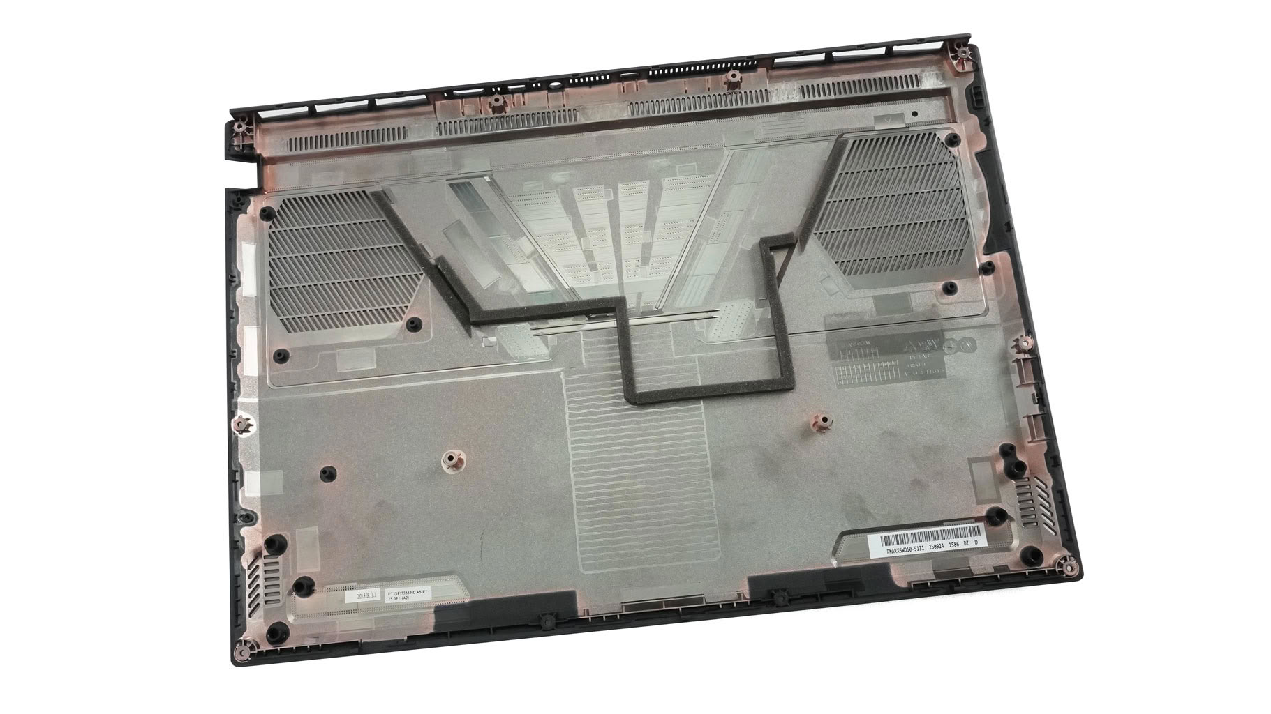
The primary SSD cooling plate has a thermal pad on top, which also makes contact with the bottom cover. The pad picture can be seen a bit further below.
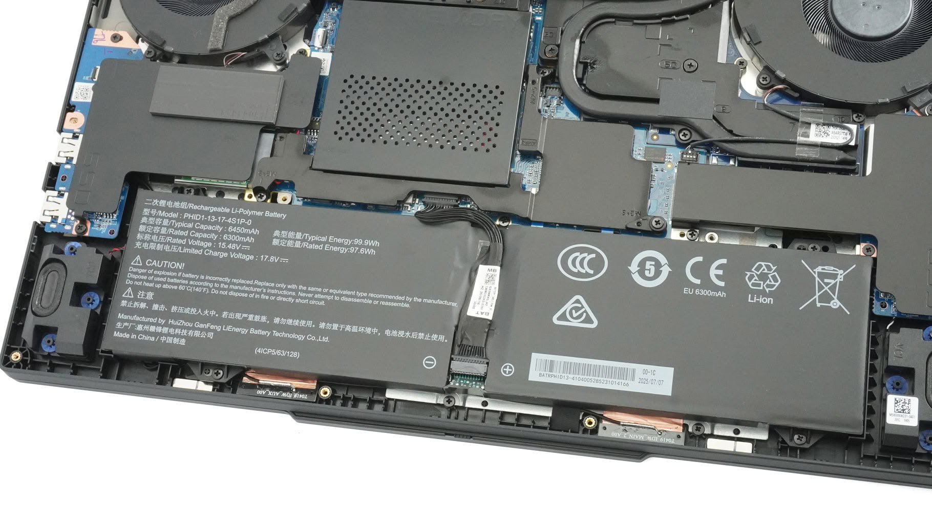
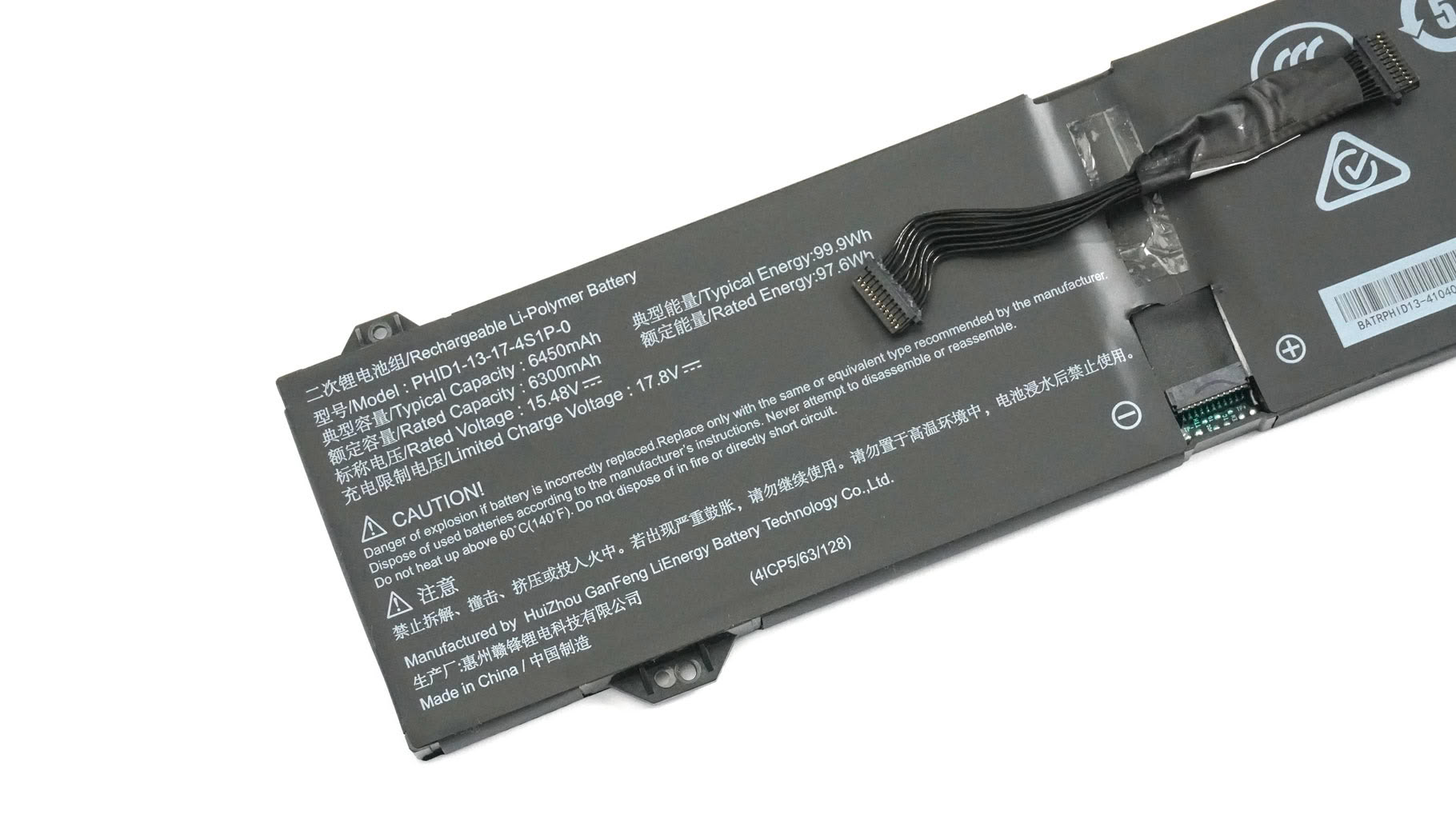
This high-end laptop packs a massive 99.9 Wh battery. If you need to remove it, you'll have to unplug the cable first. It's a dual-ended connector—one end plugs into the motherboard, and the other connects directly to the battery. I chose the easier option and pulled the battery-side plug. Next, undo the four screws securing the unit.
A full charge gives you about five and a half hours of 4K YouTube playback—a pretty standard result given the hardware and high-res Mini-LED display.
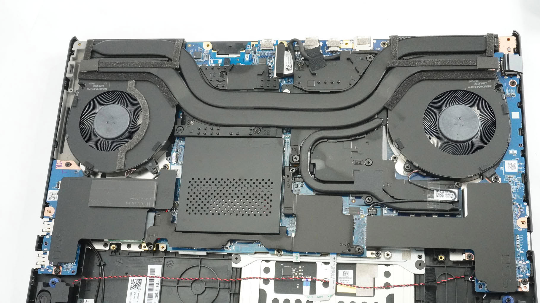
The cooling of most components is massive.
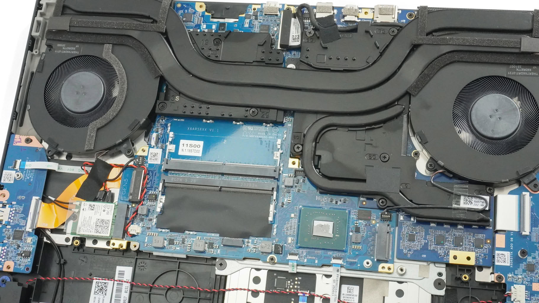
The memory section is covered by a metal shield that can be popped off with a prying tool. Inside, the shield features a large thermal pad for the bottom RAM stick and a perforated section for the top module, which relies on passive heat dissipation. The two memory slots support up to 128 GB of DDR5 RAM. Faster CSO-DIMM modules, like the ones installed here, are also compatible, supporting speeds up to 6400 MT/s depending on capacity.
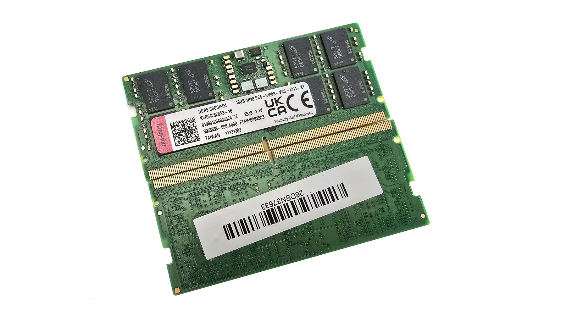
Here are the preinstalled RAM sticks.
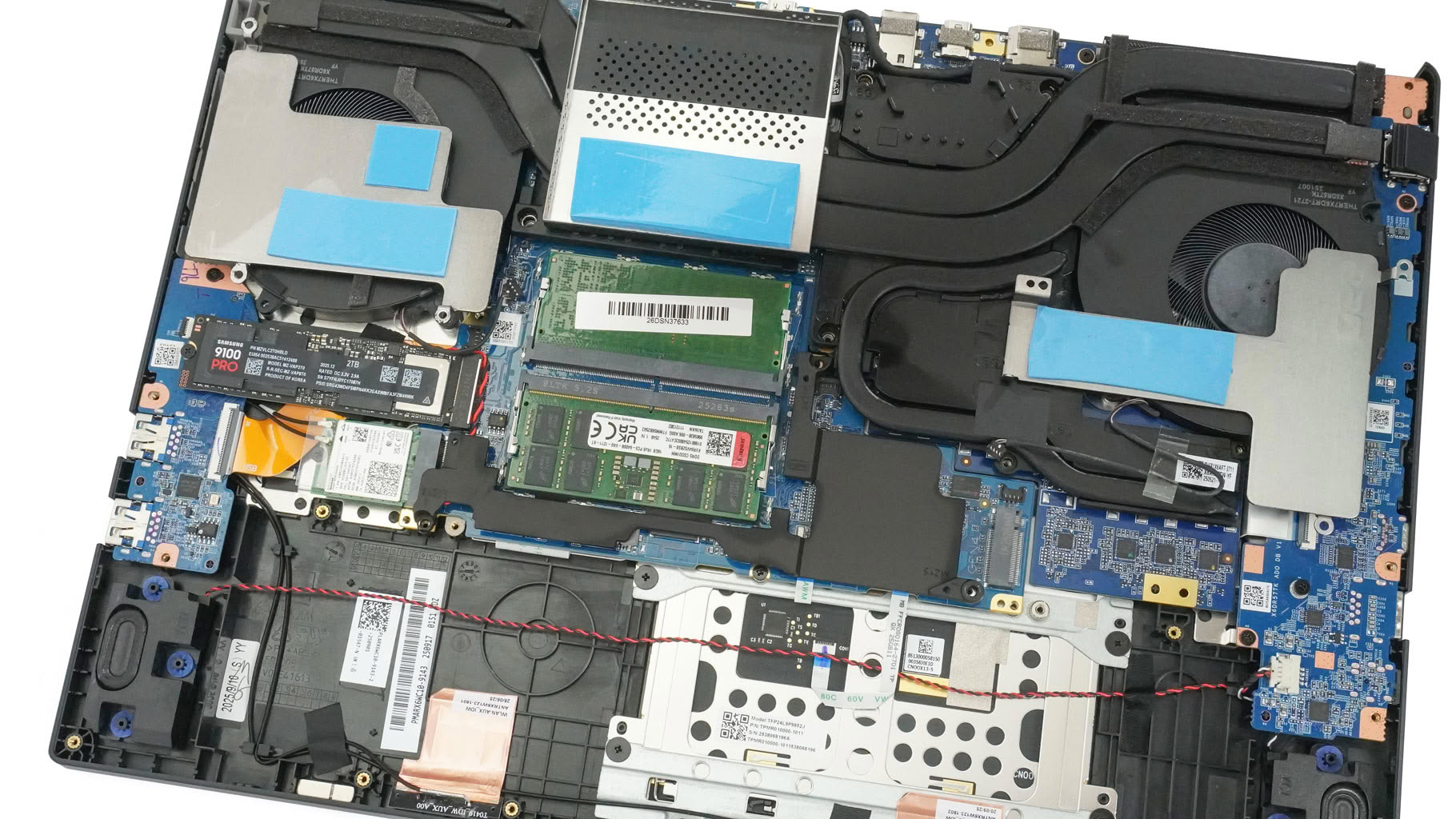
Two metal plates sit over the SSD slots—the left one supports Gen 5 units, while the right fits Gen 4 NVMe drives. Each plate is held by three screws, one of which is shared with the fan housing.
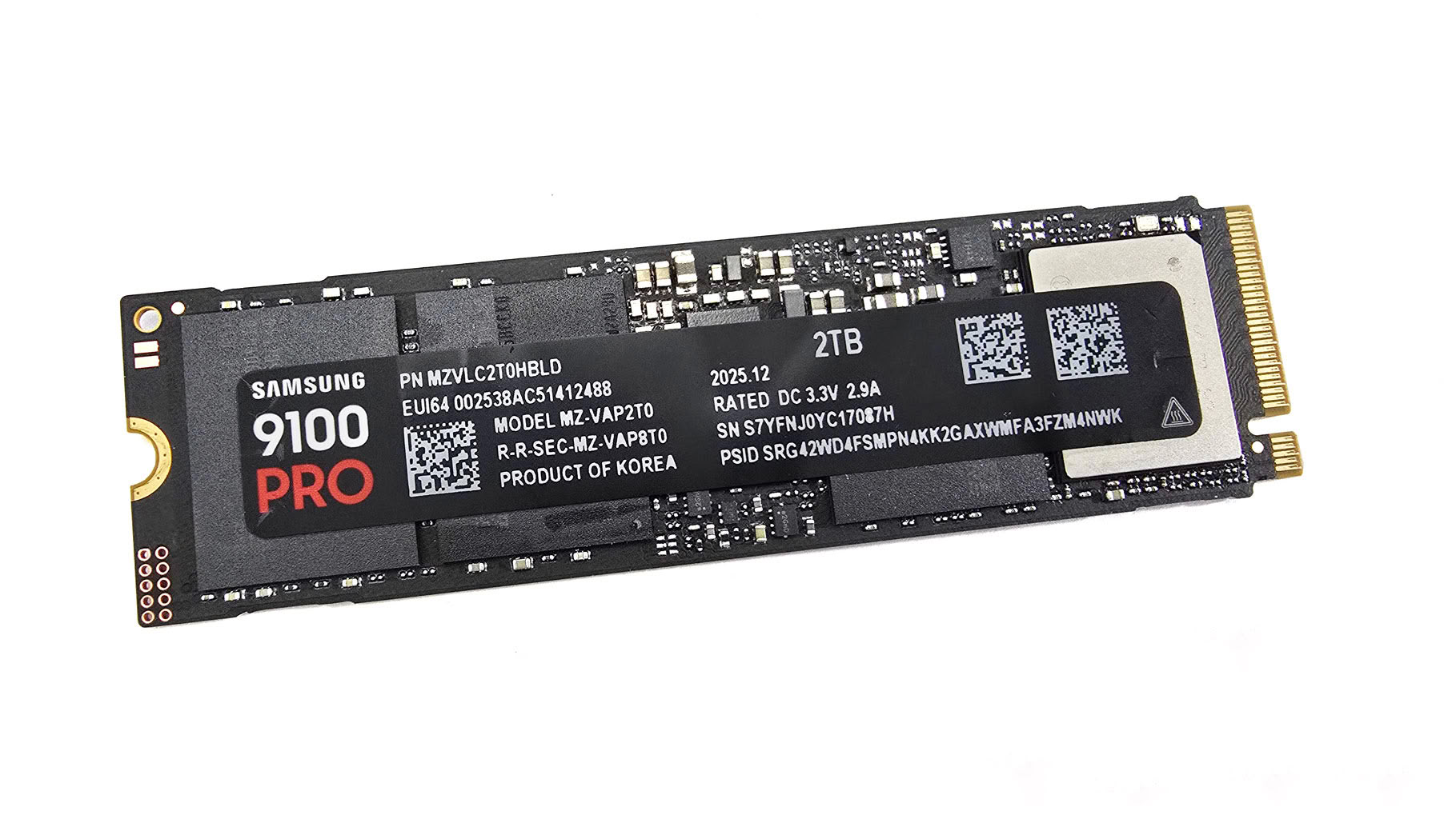
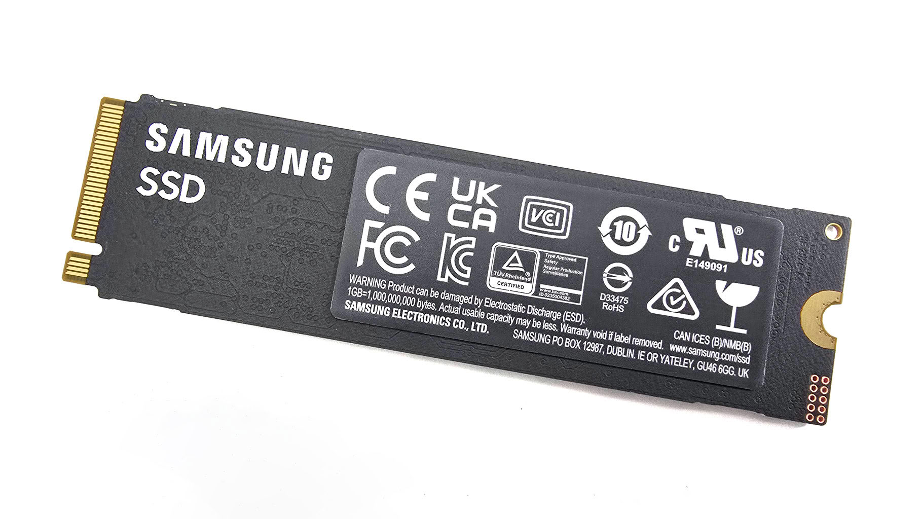
That's the Samsung SSD on both sides.
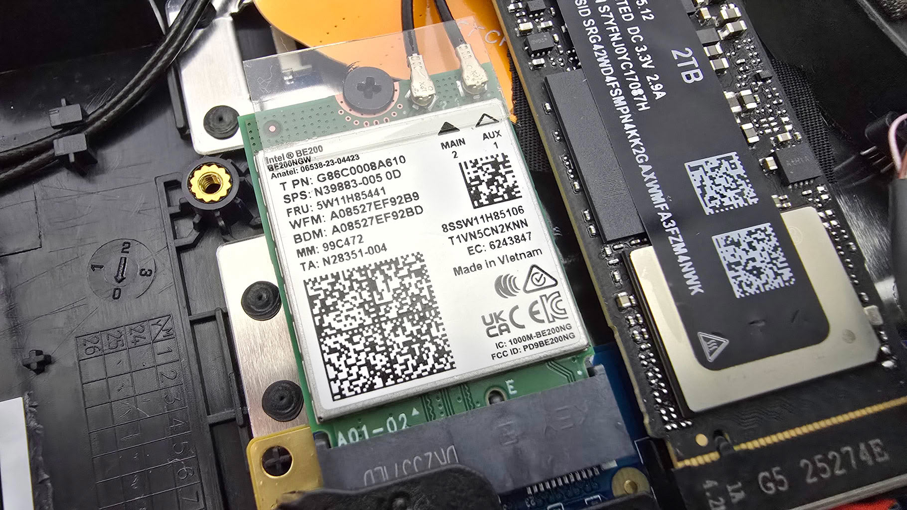
Underneath these shields, you'll find thermal pads for both SSDs and the user-replaceable Wi-Fi 7 card. That's great for the long-term longevity of these components!
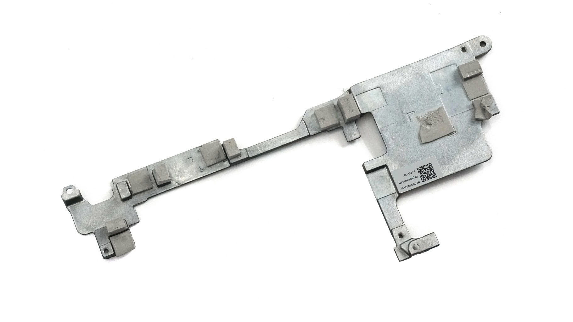
A separate metal plate cools the chipset along with several power inductors. To remove this shield, undo three screws and pop it loose with a prying tool.
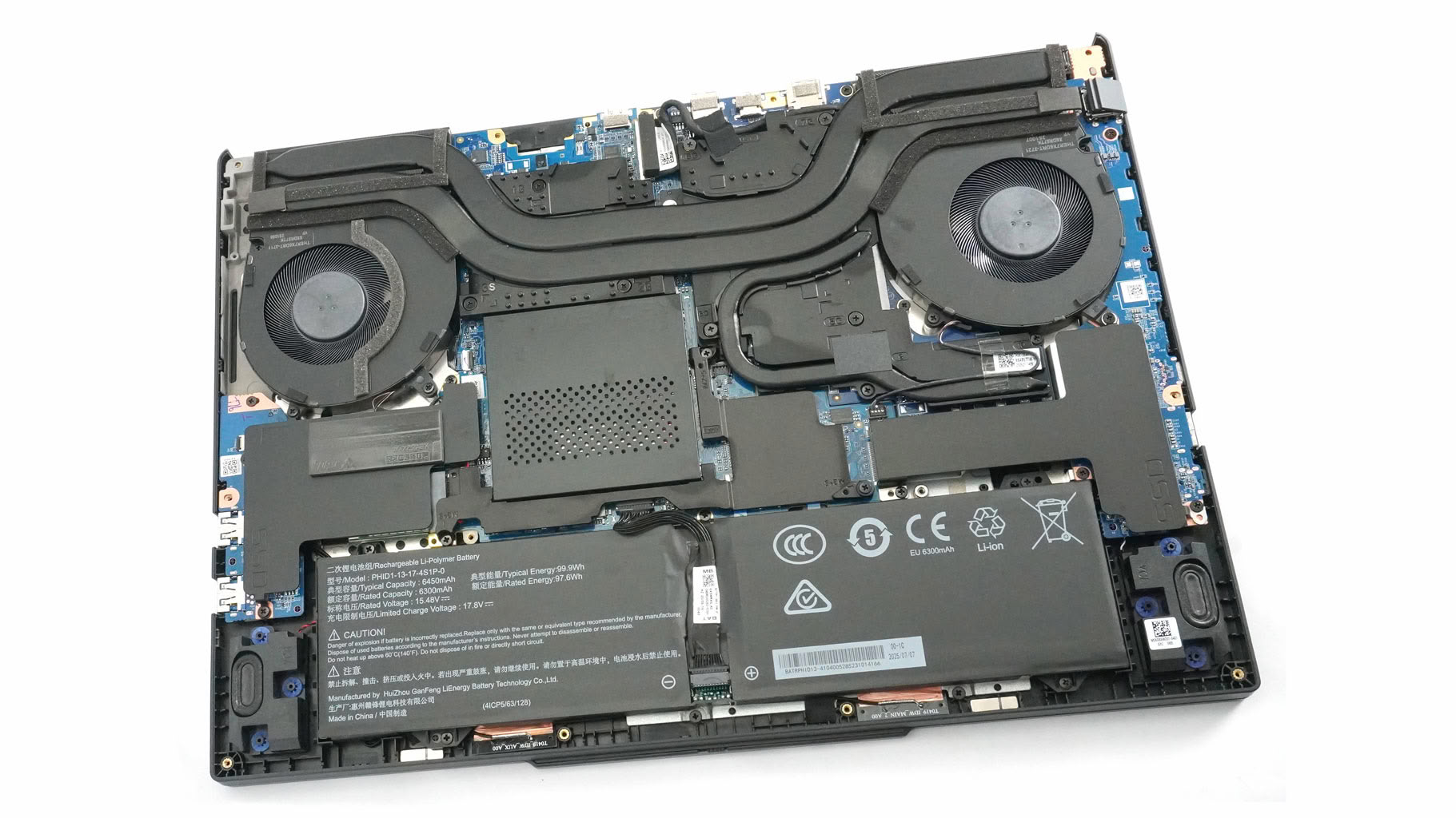
The cooling system looks serious—and it certainly is. You get two large fans and a pair of extra-thick, long heat pipes shared between the CPU and GPU. A small U-shaped pipe on the bottom right is dedicated to the graphics card, its memory, and VRM section. The main heat pipes also connect to the top heatsinks, with two cooling plates sitting directly over the CPU and GPU.
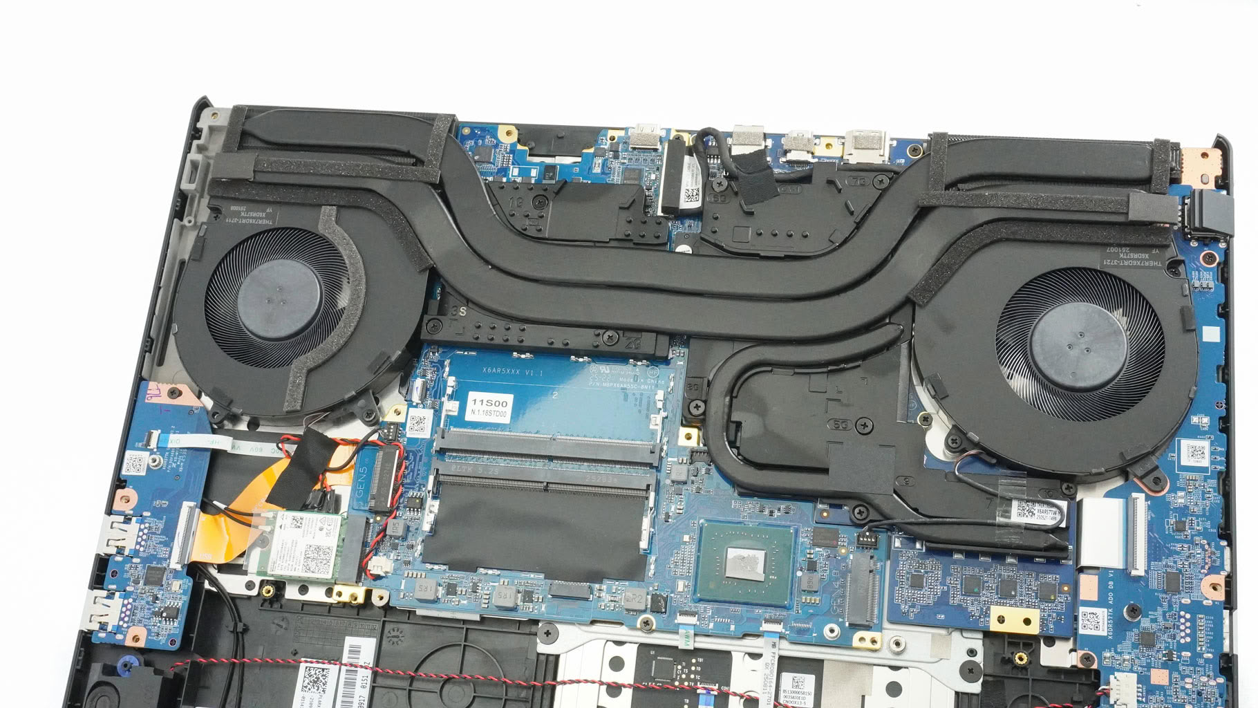
Removing the cooling assembly is straightforward. Pull the fan connectors upward and undo two screws on each housing. Next, undo three screws around the processor and six more around the graphics card. Before lifting the thermal system out, peel off two pieces of tape (top right and bottom) securing some cable. Gently pop the cooling loose with a prying tool.
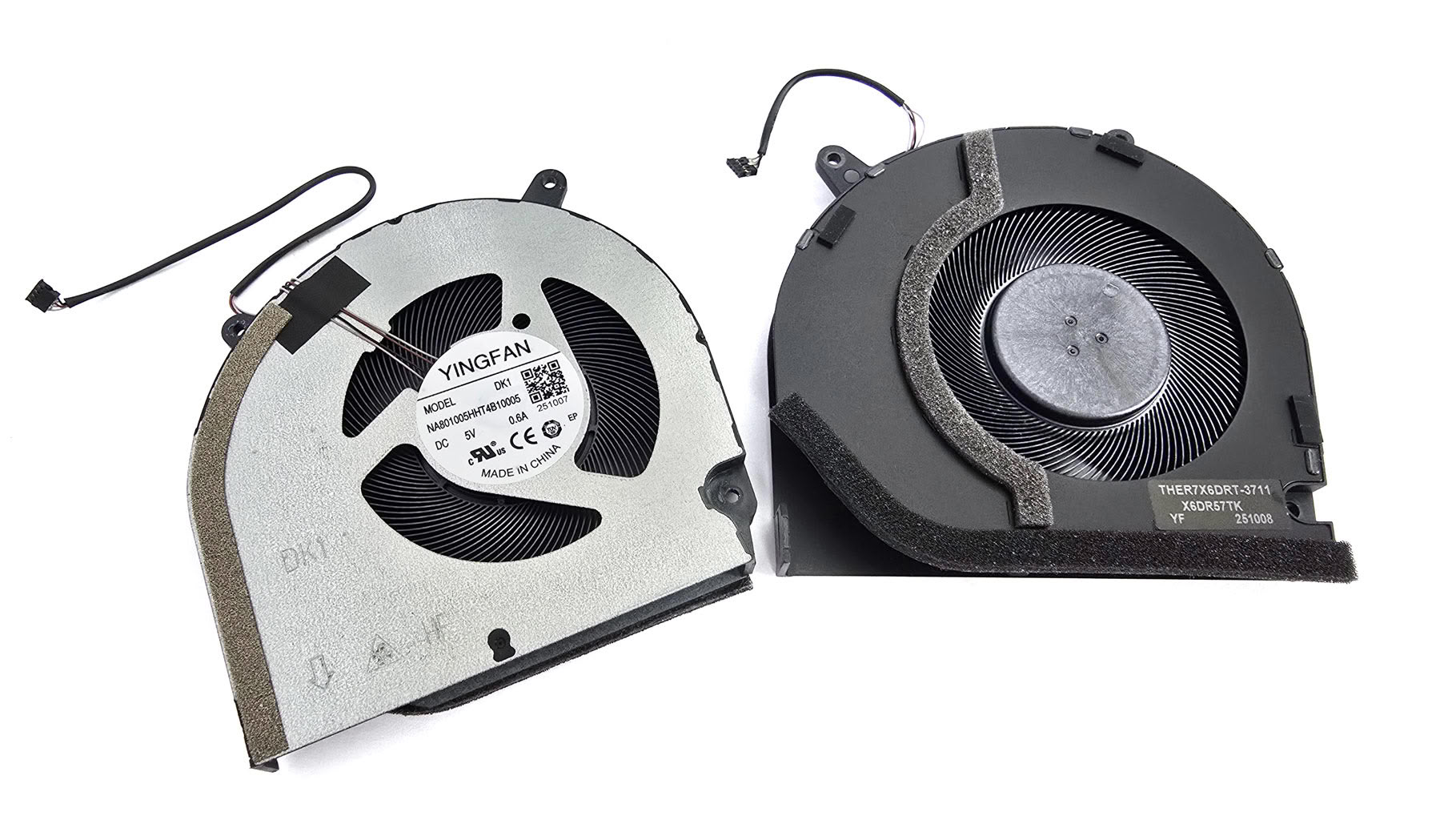
By the way, the fans aren't attached directly to the heatsink array.
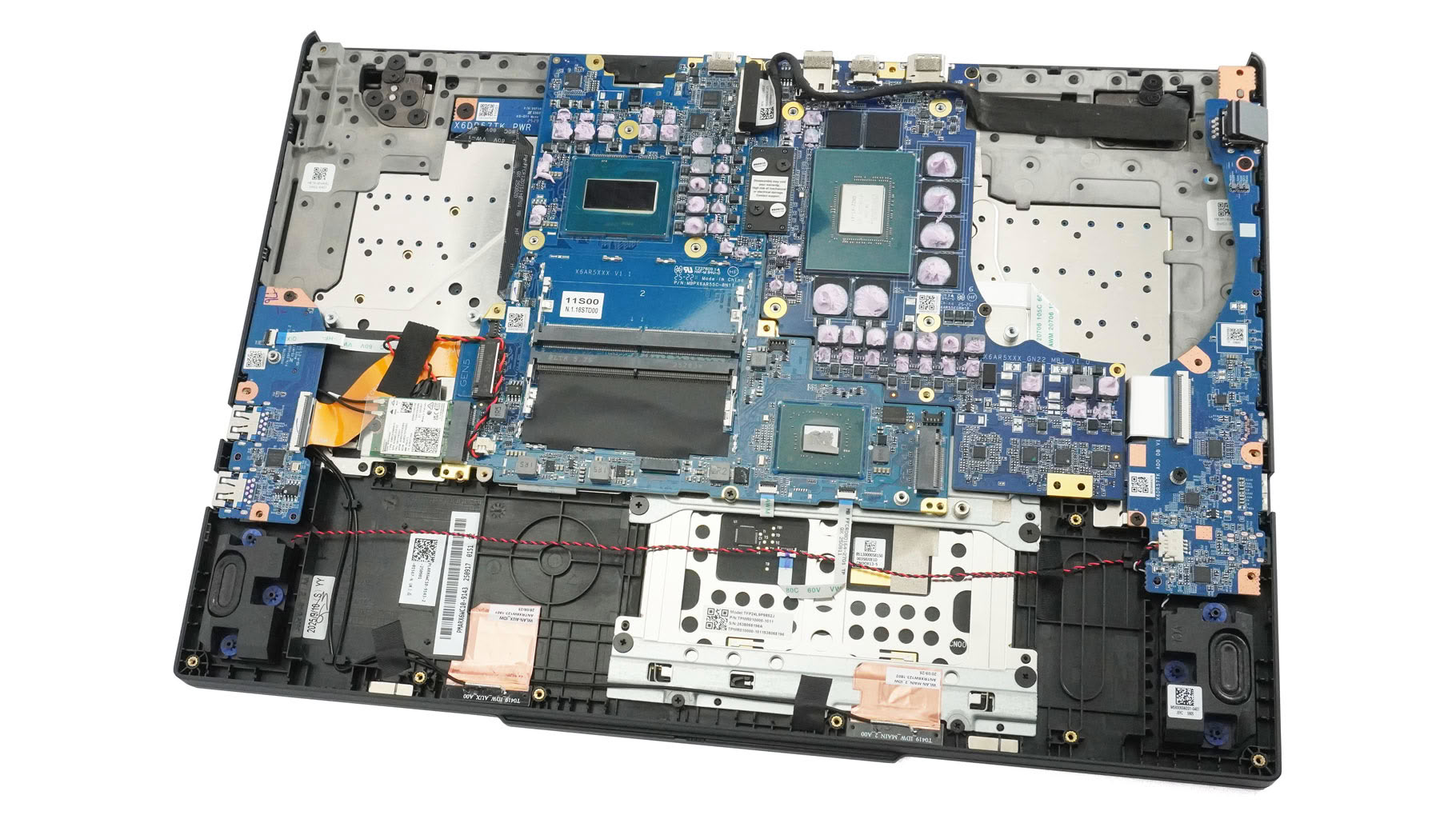
You can have a more detailed look at the motherboard.
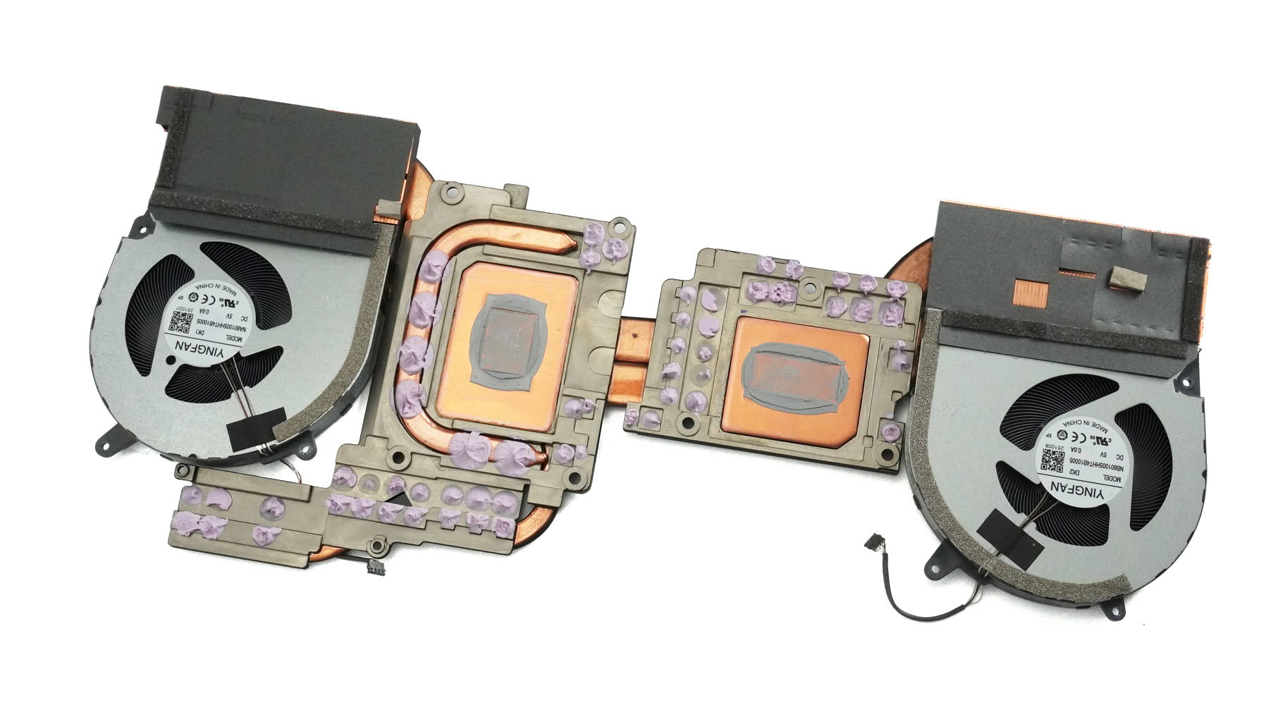
And there you have it: the underside of this well-engineered thermal system.
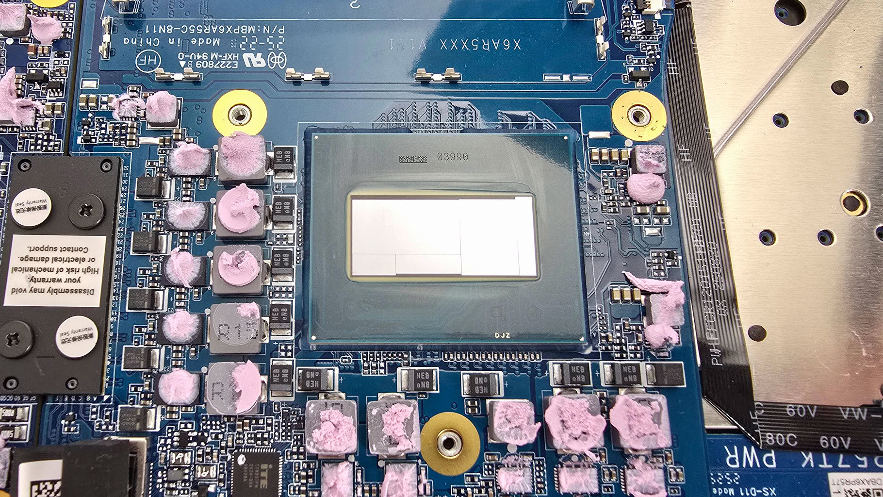
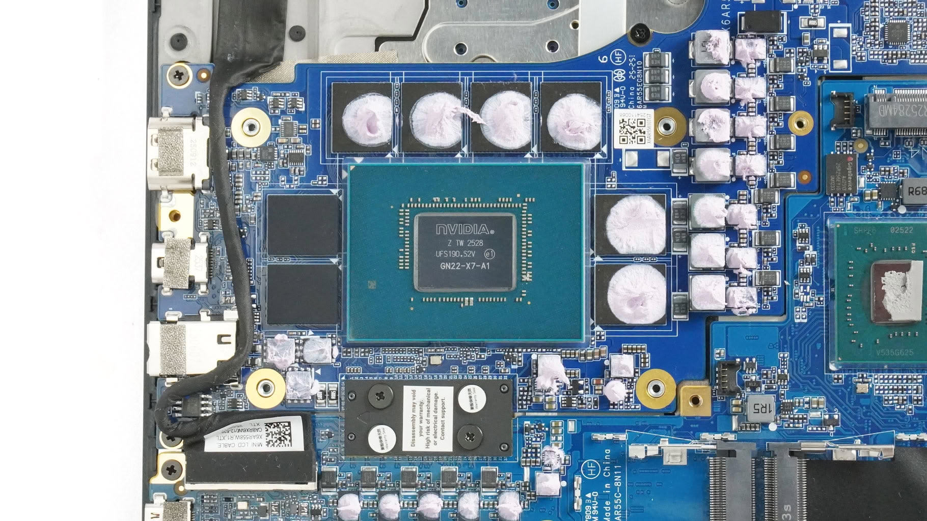
Exposed are the RTX 5070 Ti (along with its memory and massive VRM zone) and the Core Ultra 9 275HX. Both chips are treated with PTM7958 thermal compound.
Nov 17th, 2026 20:59 CST
change timezone
Latest GPU Drivers
New Forum Posts
- 9070 GRE 3.9ghz validation reached. (19)
- [testers wanted] Qsurfer My own QNAP Nas explorer/Search tool (8)
- Lenovo Legion Pro 5 Audio Nightmare: Fan Noise, Harsh Voice & Massive DPC Latency (Help!) (2)
- Help with fixing Overclock (8)
- Will zen 6 mobos have anything extra vs current ones? (51)
- WarpCoreBench scores! (56)
- Slow SSD read speeds - help! (15)
- Ryzen 7 8700G OC (9)
- Without Jensen, PC gaming will be (35)
- Honestly, do you care about GTA VI? (134)
Popular Reviews
- Acemagic Retro X3 Review
- Upcoming Hardware Launches 2027 (Updated Nov 2026)
- AMD Zen 6 Technical Deep Dive
- ASUS ROG Strix B850-I Gaming Wi-Fi7 W Review
- Corsair HX1000i Shift Crystal Review
- Chieftec Iceberg PRO 360 DARK Review
- AMD Ryzen 7 9800X3D Review - The Best Gaming Processor
- Phantom Blade Zero Performance Benchmark Review - 35 GPUs Tested
- Montech King 95 3D PRO Review
- Biwin Black Opal NV7400 2 TB Review
TPU on YouTube
Controversial News Posts
- NVIDIA Co-Founder and CEO Jensen Huang Officially Resigns (464)
- Open Letter Asking NVIDIA to Reinstate Jensen Huang Passes 115,000 Signatures (184)
- OpenAI CEO Argues Home PCs Waste the World's Limited DRAM Supply (152)
- Report: Jensen Huang Eyes NVIDIA Comeback (137)
- NVIDIA Launches Investigation Into Jensen Huang's Relationship With Suspected Chinese Spy (136)
- Intel "Raptor Lake Next" 16-Core and 20-Core CPUs Surface (130)
- Legendary Game Studio BioWare Shuts Down Following EA Layoffs (104)
- Dell CEO Says the Memory Shortage Will Get Worse in 2027 (95)