 18
18
ASUS MAXIMUS IX CODE Review
BIOS Overview »Board Layout
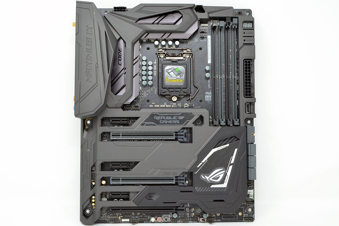

Taking the ASUS MAXIMUS IX CODE out of the box reveals a black board with a gunmetal gray shield covering most of its surface. Near the socket, brushed aluminum heat sinks peak out from under the shield, while down to the right of the PCI slots, a black heat sink can be found to be glimpsing out from under a black, removable shield that hides the first M.2 slot as well as the CMOS battery.
The overall impression the ASUS MAXIMUS IX CODE creates when examined is one of durability and quality. I really like the color scheme, though I don't like the color mismatch between the main gray shield and smaller black shield. The backside of the board continues the black theme and also reveals the nine screws that keep the shield attached.


The socket is somewhat open; though it does feel more crowded than on some boards, it should offer good clearance for coolers. The four DIMM slots sit to the right of the socket with a POST code display and start and reset buttons.
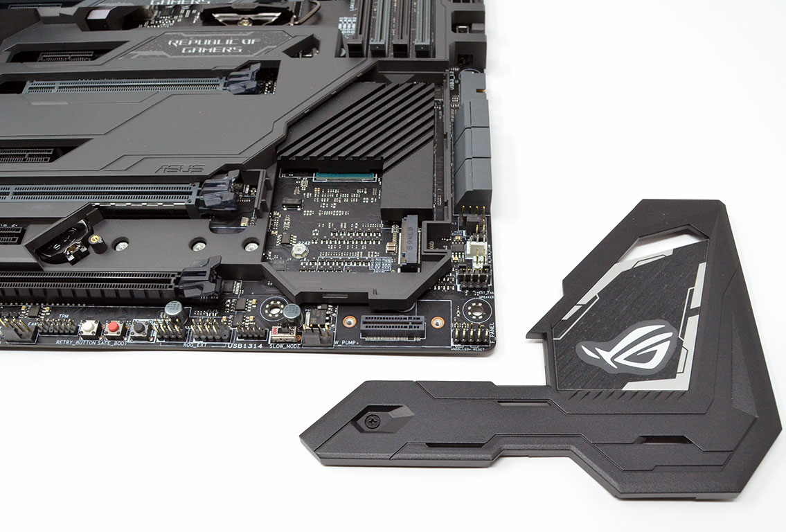
There are two M.2 slots of which the first is between PCI x16 slots two and three, underneath the small black shield bearing the ROG logo. The second slot is less conventional, located in the bottom-right corner. This slot requires an included adapter to mount the drive perpendicular to the board. This mounting method seems obtuse, but there is a lot going on with the ASUS MAXIMUS IX CODE, and real estate is a resource in short supply.
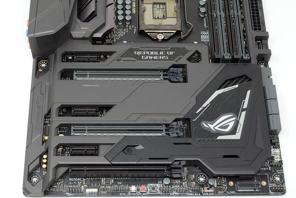
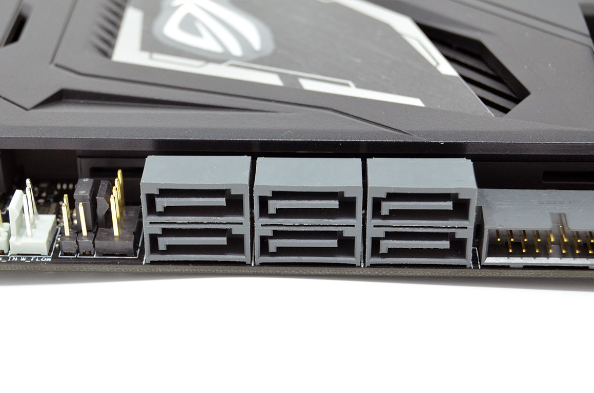
The ASUS MAXIMUS IX CODE features three PCI x16 and three PCI x1 slots. The top two PCI x16 slots are metal-reinforced. There are six standard SATA 6 Gb/s plugs on the board's right edge, angled at 90 degrees. The bottom edge of the board features three buttons along with a generous portion of USB, front panel, and fan headers. The white button is a hard reset, the second is a "safe boot", and the third is a "memOK". All three are extremely useful overclocking tools.


The rear I/O is fairly generous on the ASUS MAXIMUS IX CODE. Starting on the left, there are BIOS flashback and BIOS reset buttons. Next are the connections for the M.2 Wi-Fi antenna, followed by an HDMI 1.4b and a DisplayPort 1.2. Four USB 2.0 ports in black and four USB 3.0 ports in blue come next. The RJ45 LAN port sits over the two USB 3.1 ports, a Type-A in red and a Type-C in black. Finally, there are five color-coded 3.5 mm audio jacks and an optical S/PDIF out.
Apr 26th, 2024 03:34 EDT
change timezone
Latest GPU Drivers
New Forum Posts
- TPU's Nostalgic Hardware Club (18466)
- Which new games will you be buying? (317)
- AMD RX 7000 series GPU Owners' Club (1088)
- Best SSD for system drive (82)
- What phone you use as your daily driver? And, a discussion of them. (1484)
- What's your latest tech purchase? (20342)
- im new to throttelstop and i think i messed it up by copying others any hints would be very much aprreciated (3)
- Horizontal black lines popping up on my screen? (4)
- Alphacool CORE 1 CPU block - bulging with danger of splitting? (20)
- Black screen after muting (5)
Popular Reviews
- Fractal Design Terra Review
- Thermalright Phantom Spirit 120 EVO Review
- Corsair 2000D Airflow Review
- ASUS GeForce RTX 4090 STRIX OC Review
- NVIDIA GeForce RTX 4090 Founders Edition Review - Impressive Performance
- ASUS GeForce RTX 4090 Matrix Platinum Review - The RTX 4090 Ti
- MSI GeForce RTX 4090 Suprim X Review
- Gigabyte GeForce RTX 4090 Gaming OC Review
- MSI GeForce RTX 4090 Gaming X Trio Review
- MSI GeForce RTX 4090 Suprim Liquid X Review
Controversial News Posts
- Sony PlayStation 5 Pro Specifications Confirmed, Console Arrives Before Holidays (117)
- Windows 11 Now Officially Adware as Microsoft Embeds Ads in the Start Menu (116)
- NVIDIA Points Intel Raptor Lake CPU Users to Get Help from Intel Amid System Instability Issues (106)
- AMD "Strix Halo" Zen 5 Mobile Processor Pictured: Chiplet-based, Uses 256-bit LPDDR5X (101)
- US Government Wants Nuclear Plants to Offload AI Data Center Expansion (98)
- AMD's RDNA 4 GPUs Could Stick with 18 Gbps GDDR6 Memory (88)
- Developers of Outpost Infinity Siege Recommend Underclocking i9-13900K and i9-14900K for Stability on Machines with RTX 4090 (85)
- Windows 10 Security Updates to Cost $61 After 2025, $427 by 2028 (84)