 5
5
Antec High Current Pro Platinum 1000 W Review
Voltage Regulation & Efficiency »A Look Inside
Before reading this page we strongly suggest to take a look at this article, which will help you understand the internal components of a PSU much better.


Like all HCP units the OEM of this one is Delta Electronics. This company is one the largest PSU manufacturer and definitely one of the best. Their implementations, especially the high-end ones, aim straight to the top of the respective categories, performance wise. Unfortunately Delta is not the most affordable OEM, meaning that their implementations do not come cheap and this is the main reason that their products are not so widely spread in the retail market. The platform Delta used for this PSU is brand new and innovative as you will see. Currently it is one of the cleanest designs we have ever seen and it utilizes really compact heatsinks, for its capacity, thanks to the restricted energy dissipation it achieves.
The HCP-1000 utilizes a full-bridge LLC topology which offers many advantages including zero voltage (or loss-less) switching at a constant switching frequency, reduced EMI and RFI noise and also the ability to use higher switching frequencies, something that greatly reduces the size of components and lowers cost. In addition in the secondary side synchronous rectification is used and the minor rails are generated through two DC-DC converters.
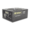
The first part of the transient filtering stage can be found on the rear side of the AC receptacle with two Y and one X caps. On the main PCB we find the remaining transient filtering components, four Y and one X caps, two CM chokes and an MOV.

The two parallel bridge rectifiers are bolted on a dedicated heatsink. Their model number is LL25XB60 and combined they can handle up to 50A of current. In front of the rectifier bridges we meet the PFC input cap and next to it three current sense resistors are installed.


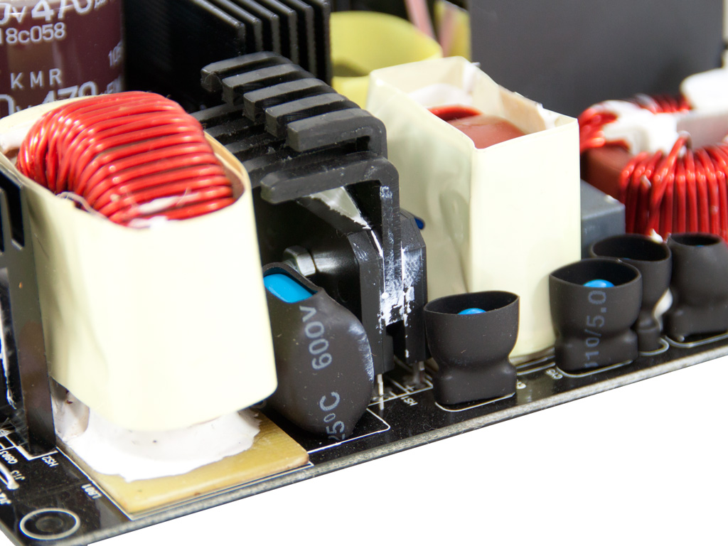
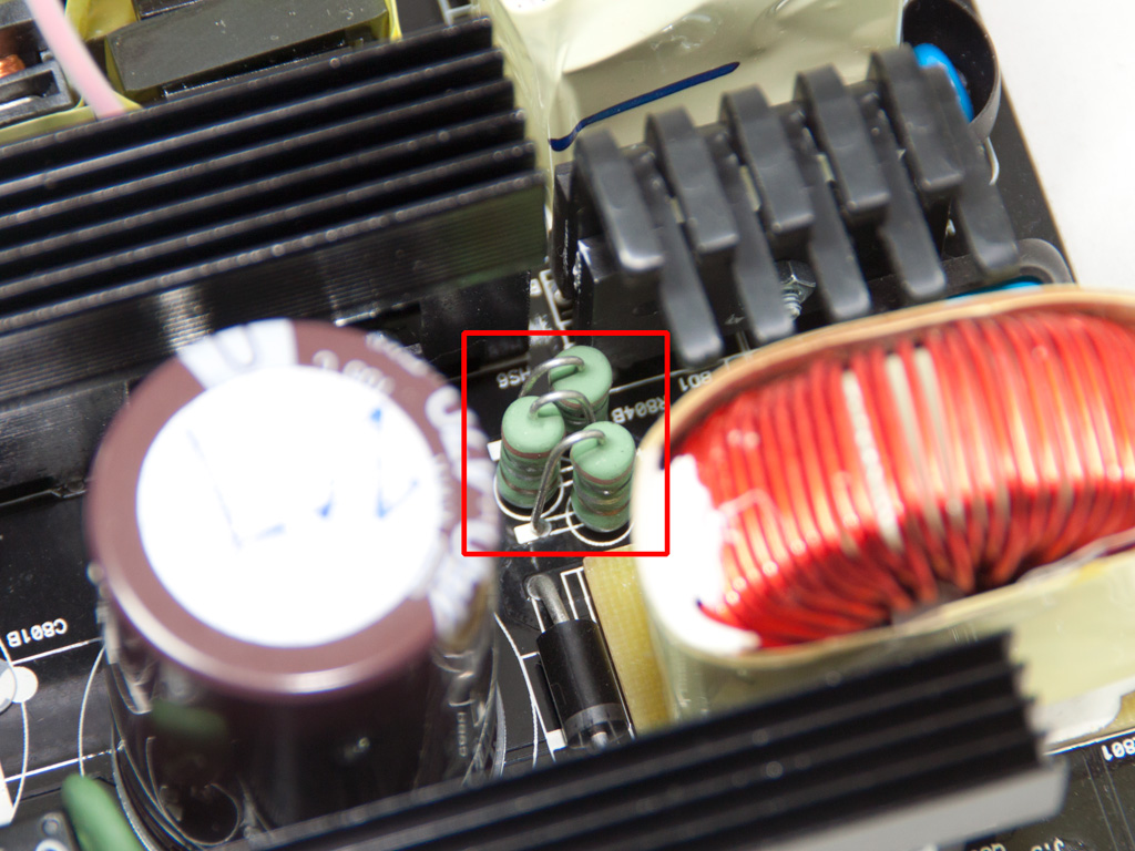
In the APFC three AOTF27S60 fets are used along with a CREE C3D10060 boost diode. The two parallel caps are provided by Nippon Chemi-Con (450V, 470μF each or 940μF combined, 105°C, KMR series). The PFC controller is mounted on a small PCB residing on the edge of the main PCB. It is a Champion CM6502S IC which according to its maker is designed to meet 90+ spec efficiency.

There is of course a thermistor for large inrush current protection and a relay to cut off the circuit once the start up phase completes.

The standby PWM controller is a TNY280PG IC. It is soldered on the main PCB and located very close to the 5VSB converter.

The four main choppers are arranged in a full bridge topology and an LLC resonant converter is utilized to provide zero voltage switching and minimize energy losses. A small dedicated heatsink is used for the primary fets, thanks to their reduced cooling requirements.


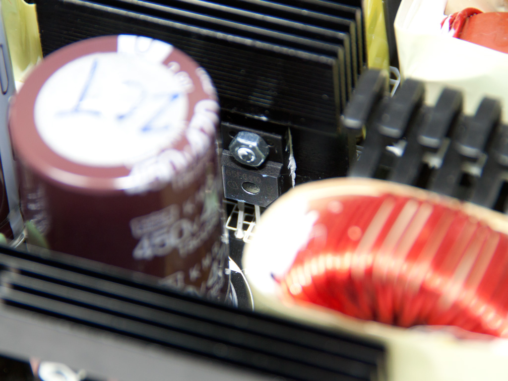
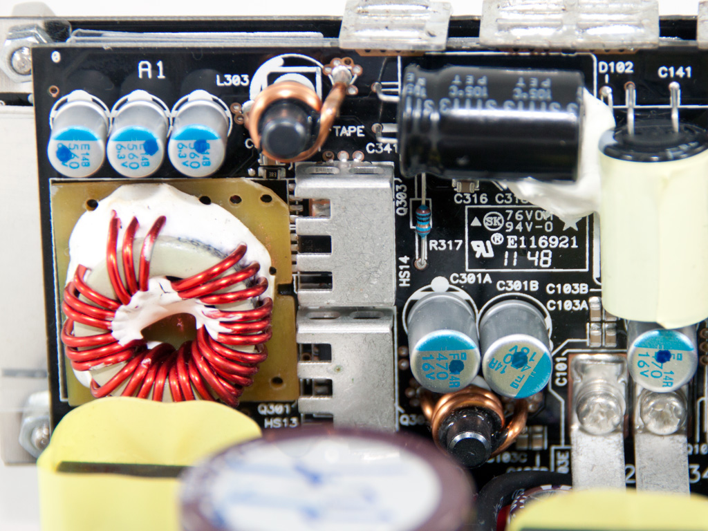
The main transformer besides compact dimensions and high density utilizes a special design which allows the fets that regulate +12V to be directly attached on it. This technique leads to minimized energy losses and reduced EMI noise. Right next to this transformer we located a UCC27324 IC which is a low side power mosfet driver. A small heatsink is firmly attached on the +12V fets to cool them down. As you can see from the photos above a great number of solid capacitors is used to filter the +12V rail along with several Nippon Chemi-Con electrolytic caps.
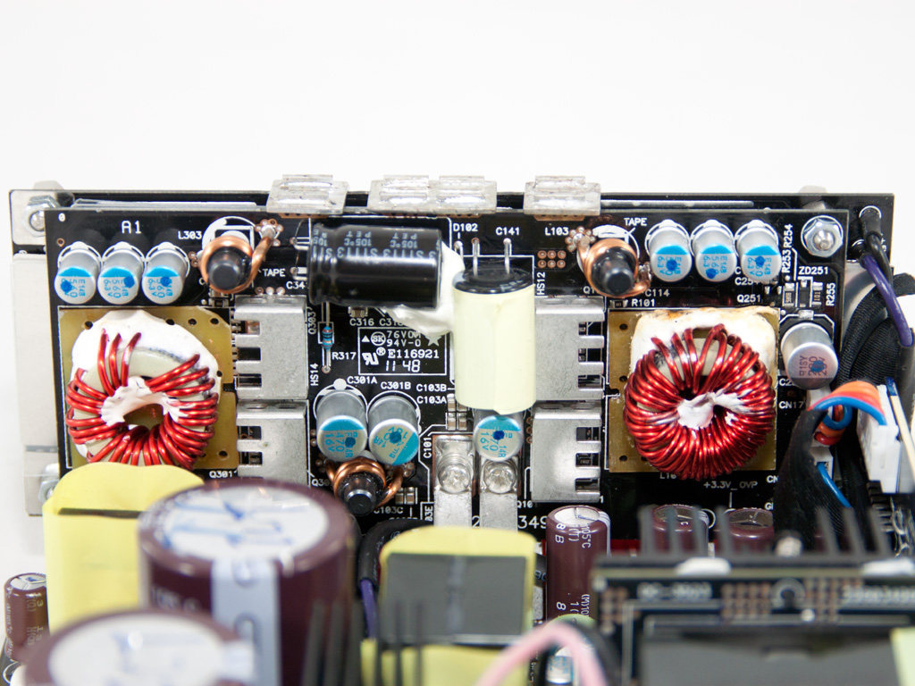


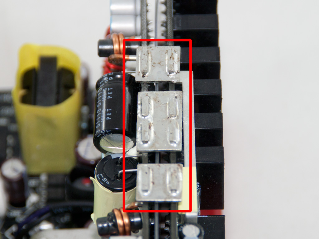
The two DC-DC converters that generate the minor rails are located on a PCB right behind the modular one. Two wide bus bars transfer the required juice (+12V) along with ground to this PCB and afterwards two pairs of fets handle each one of the two minor rails. Along with many solid capacitors two Rubycon electrolytics further filter ripple. This PCB is connected with the modular one via four bus bars located on top of it.
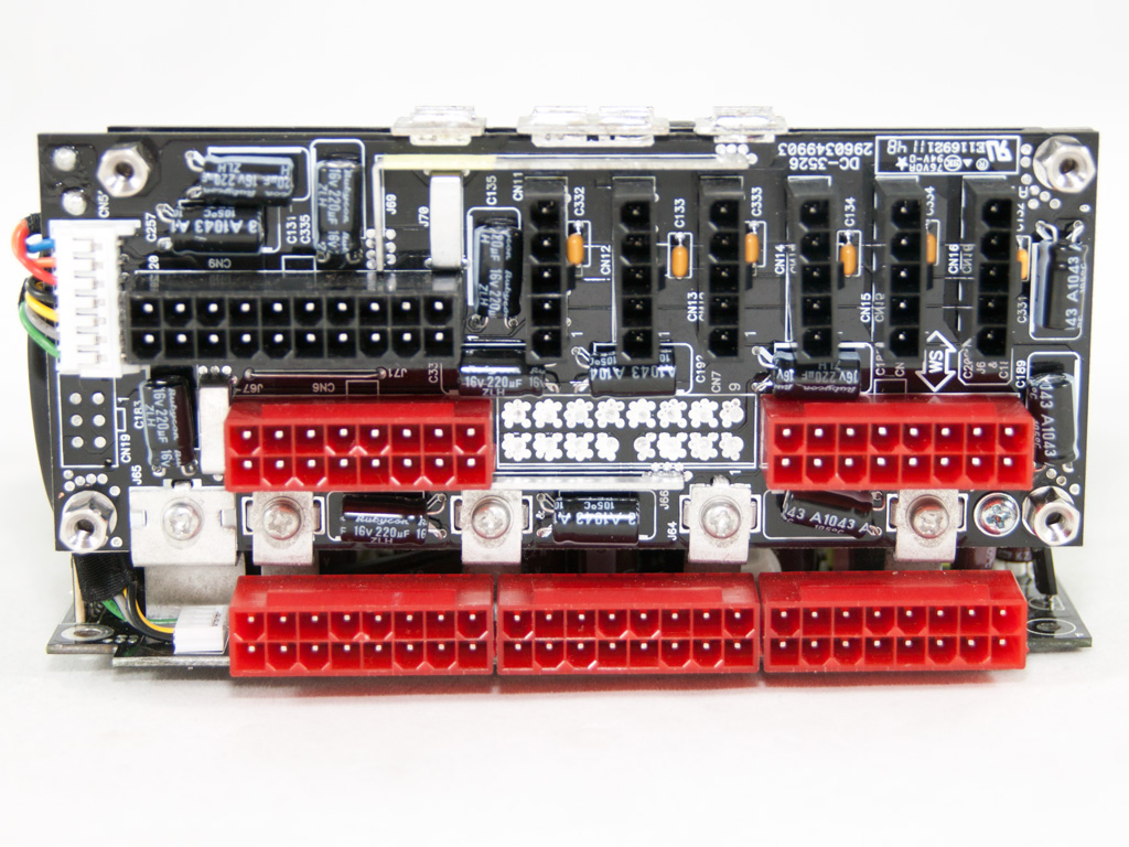

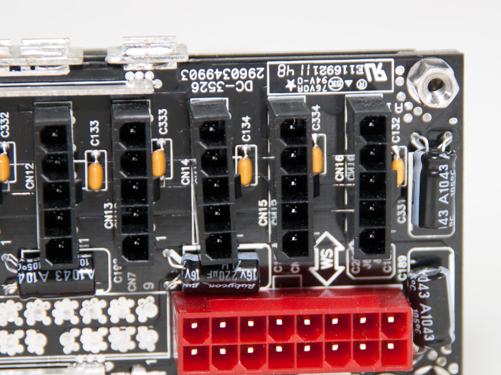


On the modular PCB we find many Rubycon electrolytic caps which remove the AC fluctuations (aka ripple) from the DC outputs. Four bus bars transfer the +12V rail to this PCB along with a wider one that provides ground. The bottom three sockets are directly soldered on the main PCB, in order to avoid extra wiring and thus reduce forward voltage drops especially at high current.


The supervisor IC is located on this vertical PCB. Its model number is DWA103N and it's exactly the same is used in the HCP-1200. On the solder side of the same PCB an AS339 quad voltage comparator is installed, to provide additional OCP channels.


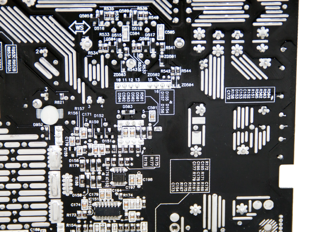

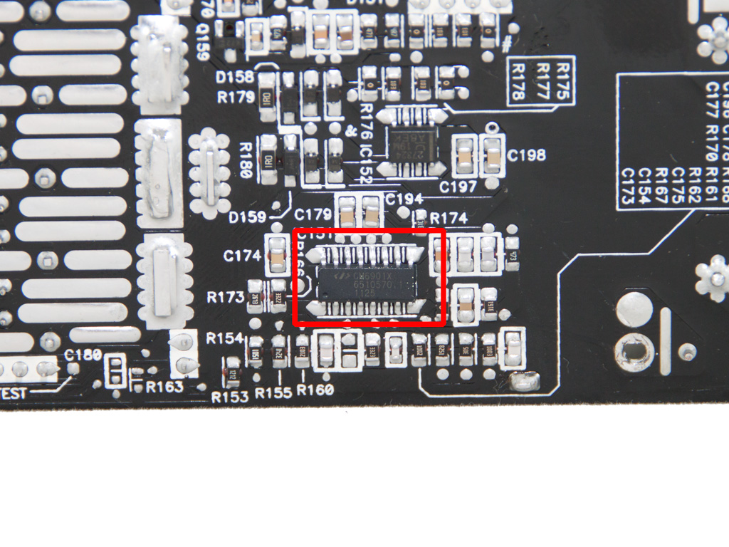
Soldering quality on the main PCB is typical Delta, meaning impeccable. Almost all solder joints are very clean and with the right amount of solder on them. Moreover all component leads are rigorously trimmed. On this side of the PCB we spotted the LLC resonant controller which is a Champion CM6901X IC. The CM6901 operates in PWM mode at lower loads while for all the rest it uses FM mode.
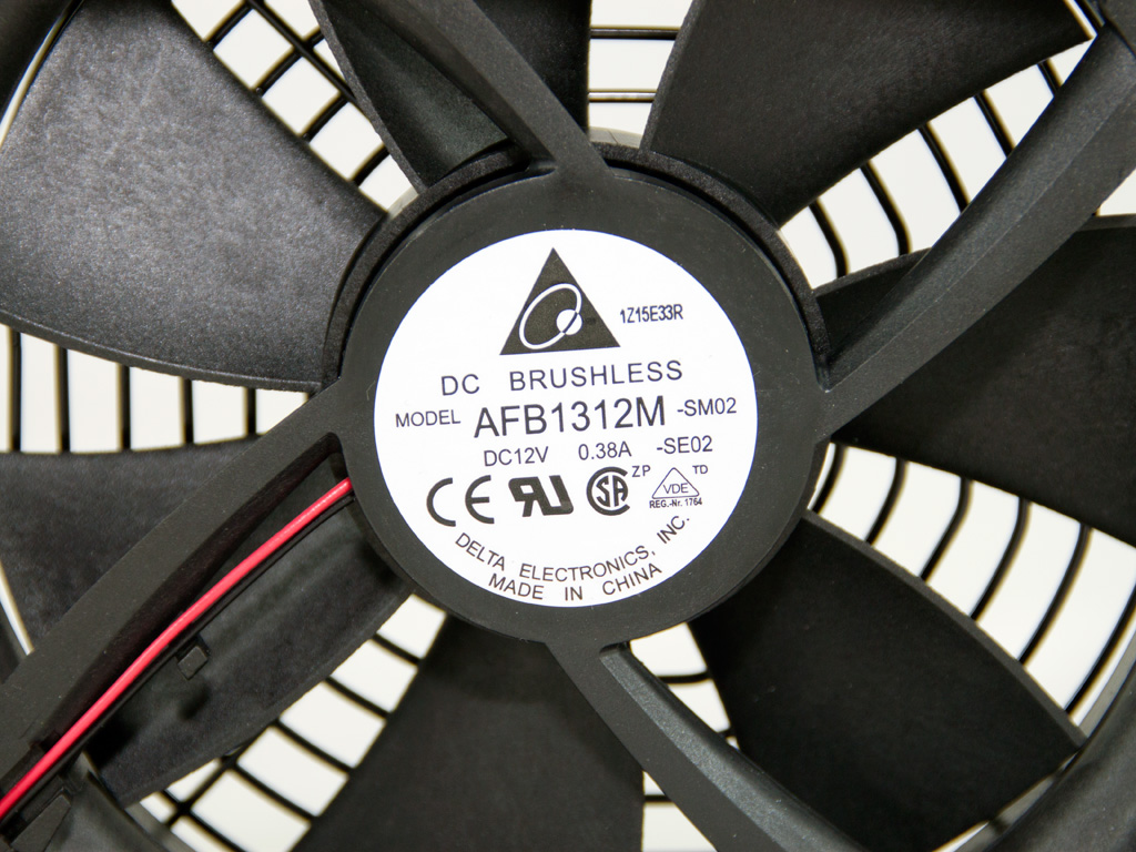
The cooling fan is provided by Delta itself, since besides PSUs the same company has a long tradition in making fans. The model number of the fan is AFB1312M (12V, 0.38A) and it is manufactured in China. Thanks to the relaxed program of its controller it keeps a low speed at lower loads/ambient and only if you stress the PSU really hard it significantly increases its speed, however, without creating an annoyingly loud noise. Nevertheless most of the time it will work silently.
Apr 26th, 2024 06:48 EDT
change timezone
Latest GPU Drivers
New Forum Posts
- Horizontal black lines popping up on my screen? (9)
- What's your latest tech purchase? (20347)
- Share your AIDA 64 cache and memory benchmark here (2918)
- Secure boot already open help (1)
- What are you playing? (20535)
- Best SSD for system drive (83)
- TPU's Nostalgic Hardware Club (18472)
- Last game you purchased? (258)
- Alphacool CORE 1 CPU block - bulging with danger of splitting? (22)
- Nvidia CMP 100-210 or 100HX (GV100 GPU) (9)
Popular Reviews
- HYTE THICC Q60 240 mm AIO Review
- Alienware Pro Wireless Gaming Keyboard Review
- MOONDROP x Crinacle DUSK In-Ear Monitors Review - The Last 5%
- Upcoming Hardware Launches 2023 (Updated Feb 2024)
- Thermalright Phantom Spirit 120 EVO Review
- ASUS Radeon RX 7900 GRE TUF OC Review
- RTX 4090 & 53 Games: Ryzen 7 5800X vs Ryzen 7 5800X3D Review
- NVIDIA RTX 4090: 450 W vs 600 W 12VHPWR - Is there any notable performance difference?
- RTX 4090 & 53 Games: Core i9-13900K vs Ryzen 7 5800X3D Review
- FiiO K19 Desktop DAC/Headphone Amplifier Review
Controversial News Posts
- Windows 11 Now Officially Adware as Microsoft Embeds Ads in the Start Menu (123)
- Sony PlayStation 5 Pro Specifications Confirmed, Console Arrives Before Holidays (117)
- NVIDIA Points Intel Raptor Lake CPU Users to Get Help from Intel Amid System Instability Issues (106)
- AMD "Strix Halo" Zen 5 Mobile Processor Pictured: Chiplet-based, Uses 256-bit LPDDR5X (101)
- US Government Wants Nuclear Plants to Offload AI Data Center Expansion (98)
- AMD's RDNA 4 GPUs Could Stick with 18 Gbps GDDR6 Memory (89)
- Developers of Outpost Infinity Siege Recommend Underclocking i9-13900K and i9-14900K for Stability on Machines with RTX 4090 (85)
- Windows 10 Security Updates to Cost $61 After 2025, $427 by 2028 (84)